Table of Contents
Advertisement
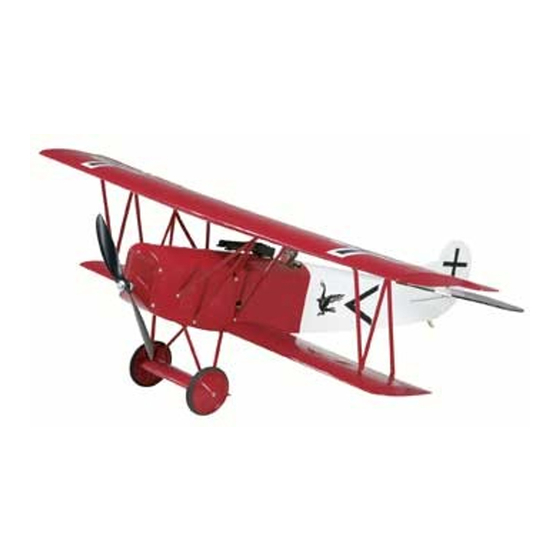
Wingspan: 36 in [914mm]
Wing Area: 360 sq in [23.2dm
Weight: 25.7 oz. [730g]
Wing Loading: 10 oz/sq ft [30g/dm
Length: 27 in [686mm]
Required (not included):
Radio: 4-channel with four micro servos
Motor: ElectriFly
™
RimFire
™
28-30-950 brushless
ESC: ElectriFly SS-25
Battery: 11.1V, 1250mAh LiPo
Great Planes
®
Model Manufacturing Co. guarantees this kit to be free from defects in both material and workmanship at the date of purchase.
This warranty does not cover any component parts damaged by use or modification. In no case shall Great Planes' liability exceed the
original cost of the purchased kit. Further, Great Planes reserves the right to change or modify this warranty without notice.
In that Great Planes has no control over the final assembly or material used for final assembly, no liability shall be assumed nor accepted for
any damage resulting from the use by the user of the final user-assembled product. By the act of using the user-assembled product, the user
accepts all resulting liability.
If the buyer is not prepared to accept the liability associated with the use of this product, the buyer is advised to return this kit
immediately in new and unused condition to the place of purchase.
To make a warranty claim send the defective part or item to Hobby Services at the address below:
Include a letter stating your name, return shipping address, as much contact information as possible (daytime telephone number, fax number,
e-mail address), a detailed description of the problem and a photocopy of the purchase receipt. Upon receipt of the package the problem will
be evaluated as quickly as possible.
READ THROUGH THIS MANUAL BEFORE STARTING
CONSTRUCTION. IT CONTAINS IMPORTANT INSTRUCTIONS
AND WARNINGS CONCERNING THE ASSEMBLY AND
USE OF THIS MODEL.
Entire Contents © Copyright 2006
INSTRUCTION MANUAL
2
]
2
]
WARRANTY
Hobby Services
3002 N. Apollo Dr., Suite 1
Champaign, IL 61822
USA
Champaign, Illinois
(217) 398-8970, Ext 5
airsupport@greatplanes.com
GPMZ1141 for GPMA1141 V1.0
™
Advertisement
Table of Contents

Subscribe to Our Youtube Channel
Related Manuals for GREAT PLANES Fokker D.VII ARF ElectriFly


Summary of Contents for GREAT PLANES Fokker D.VII ARF ElectriFly
-
Page 1: Instruction Manual
Further, Great Planes reserves the right to change or modify this warranty without notice. In that Great Planes has no control over the final assembly or material used for final assembly, no liability shall be assumed nor accepted for any damage resulting from the use by the user of the final user-assembled product. -
Page 2: Table Of Contents
TABLE OF CONTENTS Great Planes Fokker D.VII EP ARF is just what you need. INTRODUCTION ...............2 For the latest technical updates or manual corrections to the AMA...................2 Fokker D.VII EP ARF, visit the Great Planes web site at SAFETY PRECAUTIONS..........2... -
Page 3: Battery Charger Options
❏ #11 Blades (5-pack, HCAR0211) ❏ Medium T-pins (100, HCAR5150) ❏ The Great Planes Fokker D.VII EP ARF is designed for use Builder’s Triangle Set (HCAR0480) ❏ with LiPo (Lithium-Polymer) batteries only. All LiPo batteries K & S #801 Kevlar ®... -
Page 4: Important Building Notes
❏ Precision Magnetic Prop Balancer (TOPQ5700) ™ Replacement parts for the Great Planes Fokker D.VII EP ARF IMPORTANT BUILDING NOTES are available using the order numbers in the Replacement Parts List that follows.The fastest, most economical service can be provided by your hobby dealer or mail-order company. -
Page 5: Kit Inspection
If any parts are missing or are not of acceptable quality, or if you need assistance with assembly, contact Product Support. When reporting defective or missing parts, use the part names exactly as they are written in the Kit Contents list. Great Planes Product Support 3002 N. Apollo Drive, Suite 1 Champaign, IL 61822 Telephone: (217) 398-8970, ext. -
Page 6: Preparations
PREPARATIONS ASSEMBLE THE WING ❏ 1. If you have not done so already, remove the major Install the Ailerons parts of the kit from the box (wing, fuselage, tail parts, etc.) and inspect them for damage. If any parts are damaged or missing, contact Product Support at the address or telephone number on page 5. -
Page 7: Assemble The Fuselage
ASSEMBLE THE FUSELAGE Mount the Bottom Wing ❏ 2. Mark the center of the TE of the stabilizer. Place the stabilizer onto the stabilizer saddle. ❏ 1. Locate the two 4.5mm x 18mm [11/64" x 11/16"] dowel rods and insert them into the bottom wing as shown, so that only about 9.5mm [3/8"] sticks out. - Page 8 doesn’t align with the tip, adjust the stab and the arrow slightly and check both tips again. Adjust the stab until the stabilizer tips and the TE are centered. ❏ ❏ 5. View the stab from approximately 3m [10 feet] behind 8.
-
Page 9: Radio Installation
RADIO INSTALLATION Install the Motor & ESC Note: You will need to have your motor battery charged later in this section. We recommend that you start charging it now so you do not have to wait for it to charge later. Make sure to closely follow the charging instructions for charging LiPo batteries. -
Page 10: Install The Linkages
Install the Linkages ❏ 4. Attach the RimFire motor to the back of the plywood motor mount with three 3mm x 6mm [1/8" x 15/64"] machine screws. Apply a drop of threadlocker on the threads of the machine screws. Insert each of three 3mm x 30mm [1/8" x 1-3/16"] machine screws through a 3mm [1/8"] washer, the outer holes of the motor mount, another 3mm [1/8"] washer, a 17mm [21/32"] tube, and another 3mm [1/8"] washer as shown in the... -
Page 11: Install The Servos
mounting holes in the servo. Install and then remove a servo mounting screw into each of the holes you drilled. Apply a couple of drops of CA into each hole to harden the threads. After the glue has hardened, plug the ESC, rudder and elevator servos into the receiver. - Page 12 aileron servo into a 610mm [24"] Y-harness and tie the string around the other aileron plug. Be sure to secure the left aileron connection with heat-shrink tubing. ❏ 12. Install one 35mm [1-3/8"] aileron pushrod in the outer hole of the aileron servo arm and another in the outer hole of the aileron control horn.
-
Page 13: Install The Top Wing
Install the Top Wing ❏ 1. Study the above drawing carefully. There are four pairs of strut mounts. They are labeled AC9a, AC9b, AC9c, and AC9d. Test fit the bottom mounts into their respective strut mount ❏ pockets in the bottom wing. Do not glue them in place. 5. -
Page 14: Finish The Model
FINISH THE MODEL ❏ 8. Use four 2mm x 7mm [5/64" x 9/32"] self-tapping washer head screws to finish fastening the end struts in place as shown. Once you have determined that the wing is straight, with no twists, use thin CA to glue the strut mounts into the ❏... - Page 15 Remove the screws and harden the holes with thin CA. Then, side of the cowl as shown. Install and then remove a reinstall the screws. 2mm x 7mm [5/64" x 9/32"] self-tapping washer head screw into each of the holes you drilled. Apply a couple of drops of CA into each hole to harden the threads.
-
Page 16: Get The Model Ready To Fly
❏ 2. Sand each half using 150- or 220-grit sandpaper and Warning! Once the battery is connected to the ESC, stay a Great Planes Easy-Touch ™ bar sander. clear of the propeller even if the ESC has not been armed. -
Page 17: Set The Control Throws
Later, you may wish to experiment by shifting the C.G. up to 3mm [1/8"] forward or 3mm [1/8"] back to Use a Great Planes AccuThrow (or a ruler) to accurately change the flying characteristics. Moving the C.G. forward measure and set the control throw of each control surface as may improve the smoothness and stability, but the model indicated in the chart that follows. -
Page 18: Preflight
We use a Top Flite Precision Magnetic Prop Balancer ™ sleeves, ties, scarfs, long hair or loose objects such as (TOPQ5700) in the workshop and keep a Great Planes pencils or screwdrivers that may fall out of shirt or jacket Fingertip Prop Balancer (GPMQ5000) in our flight box. -
Page 19: Ama Safety Code (Excerpts)
AMA SAFETY CODE (excerpts) CHECK LIST Read and abide by the following excerpts from the Academy During the last few moments of preparation your mind may of Model Aeronautics Safety Code. For the complete Safety be elsewhere anticipating the excitement of the first flight. Code refer to Model Aviation magazine, the AMA web site or Because of this, you may be more likely to overlook certain the Code that came with your AMA license. -
Page 20: Takeoff
D.VII will perform loops, hammerheads, inverted flight and rolls. CAUTION (THIS APPLIES TO ALL R/C AIRPLANES): If, while When performing rolls you will find that the rolls are more of a flying, you notice an alarming or unusual sound such as a low- barrel roll.
Need help?
Do you have a question about the Fokker D.VII ARF ElectriFly and is the answer not in the manual?
Questions and answers