Table of Contents
Advertisement
Quick Links
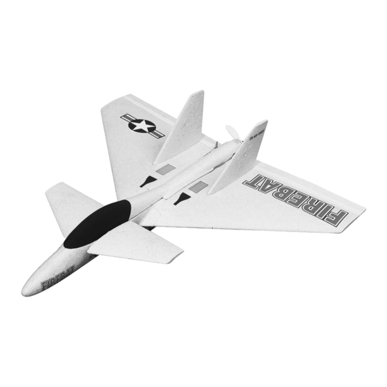
Wingspan: 31-1/4 in [794mm]
Wing Area: 343 sq in [22.1 dm
Weight: 24 oz. [680g]
Wing Loading: 10.1 oz./sq. ft. [30.8g dm
Fuselage Length: 31-3/4 in [800mm]
Motor: Speed 400, 7.2 volt
Great Planes
®
Model Manufacturing Co. guarantees this kit to be free from defects in both material and workmanship at the date of
purchase. This warranty does not cover any component parts damaged by use or modification. In no case shall Great Planes' liability
exceed the original cost of the purchased kit. Further, Great Planes reserves the right to change or modify this warranty without notice.
In that Great Planes has no control over the final assembly or material used for final assembly, no liability shall be assumed nor accepted
for any damage resulting from the use by the user of the final user-assembled product. By the act of using the user-assembled product,
the user accepts all resulting liability.
If the buyer is not prepared to accept the liability associated with the use of this product, the buyer is advised to return this kit
immediately in new and unused condition to the place of purchase.
READ THROUGH THIS MANUAL BEFORE STARTING
CONSTRUCTION.
INSTRUCTIONS AND WARNINGS CONCERNING
THE ASSEMBLY AND USE OF THIS MODEL.
GPMZ0242 for GPMA1400/1405 V1.0
INSTRUCTION MANUAL
2
]
]
2
IT
CONTAINS
WARRANTY
IMPORTANT
™
1610 Interstate Drive Champaign, IL 61822
(217) 398-8970, Ext. 2
airsupport@greatplanes.com
Entire Contents © Copyright 2002
Advertisement
Table of Contents

Related Manuals for GREAT PLANES Firebat


Summary of Contents for GREAT PLANES Firebat
-
Page 1: Instruction Manual
Further, Great Planes reserves the right to change or modify this warranty without notice. In that Great Planes has no control over the final assembly or material used for final assembly, no liability shall be assumed nor accepted for any damage resulting from the use by the user of the final user-assembled product. -
Page 2: Table Of Contents
Even while gliding with the motor off TABLE OF CONTENTS the Firebat ARF could possibly cause injury to yourself or spectators and damage property. INTRODUCTION ................2 2. You must assemble the Firebat ARF according to the PRECAUTIONS ................2... -
Page 3: Additional Items Required
In addition to common household tools, here is the list of items used to build the Firebat ARF. ❏ 6-minute epoxy (GPMR6042) ❏ The Firebat ARF requires a three-channel radio with two 1/2 oz. Thin CA+ (GPMR6001) ❏ servos, a receiver and an electronic speed controller with Hobby knife (HCAR0105) ❏... -
Page 4: Parts List
PARTS LIST Parts-Standard Version Key # Description LEFT FUSELAGE ............1 Key # Description PROPELLERS .............2 MAIN WING ..............1 LEFT CANARD ............1 BALSA KEEL ...............1 MOTOR ................1 REAR HATCH ..............1 MOTOR MOUNT PARTS BAG ........1 RIGHT VERTICAL FIN..........1 RIGHT FUSELAGE............1 Parts-Deluxe Version (*not shown, includes all parts shown above plus the RIGHT CANARD............1 following items) HARDWARE BAG............1... -
Page 5: Important Building Notes
(i.e., will be installed in front of the servos later. 1200 mAh divided by 300 mA = 4 hours). The Firebat Electric ARF is so much fun to fly you should also consider obtaining an additional battery or two and a field charger. -
Page 6: Join The Wing & Fuselage
❏ ❏ 3. The 5/32" x 5/32" x 6" [4 x 4 x 152mm] hardwood stick 6. Install a servo lead extension that will connect the will be glued into the molded channel below the servos in electronic speed control (ESC) to the receiver in the channel the next step. -
Page 7: Install The Ailerons
Install the Ailerons ❏ 3. Make a hole in each aileron to allow the control horn to come through from below the aileron. The hardwood stick should seat squarely in the groove in the bottom of the aileron. Trim the hardwood stick to length if needed. The hardwood stick will seat better in the groove if the corner of the stick is rounded slightly with some sandpaper. - Page 8 be easily seen. Note: The aileron will be attached to the wing in step 9. ❏ ❏ 8. Put a small bend 1-3/8" [35mm] from the end of a long aileron pushrod, on the end with the Z-bend. If the Z-bend does not have clean 90°...
-
Page 9: Assemble The Canards
aileron, but not onto the top of the wing. Deflect the aileron down while holding it in position against the wing. One section at a time, press the tape onto the top of the wing. ❏ 11. Return to step 7 and install the left aileron using the same procedure. - Page 10 onto the elevator horn. Slide the canard (elevator) horn onto the joiner tube, oriented as shown in the photo. Continue to slide the joiner tube through the second bearing tube. ❏ 6. Connect one of the short pushrod wires with a Z-bend to the elevator horn in the second hole from the center.
-
Page 11: Install The Canopy
may need to trim the inside edge of the canopy slightly to Install the Canopy clear the servos. ❏ 1. Cut a 3/4" [19mm] piece from the 3/8" x 3/8" [9.5 x 9.5mm] balsa stick. Screw the metal hook into the center of ❏... -
Page 12: Mount The Motor
If it is a very tight fit, you can trim the foam slightly. Continue with step 5. The motor supplied with the Firebat ARF has capacitors internally installed in the motor and is shown being installed in the following steps. There are many other higher performance motors that can also be installed and we have included a couple of photos of these installations as well. -
Page 13: Final Assembly
Note: The motor is supplied with a flux ring installed. This ring is present in the preceding photo and those that follow and should be removed for the first flights. This ring will increase flight time by reducing the current flow to the motor. There is also a slight reduction in power. - Page 14 ❏ darker of the two wires. The ESC has plugs on the wires 8. The Firebat ARF is balanced 4-1/2" [115mm] aft of the which can be pressed onto the motor terminals, or the leading edge of the wing, where it meets the fuselage. Make...
-
Page 15: Prepare The Model For Flying
❏ 9. Also place a mark on the leading edge of the wing 6-7/8" [175mm] from the fuselage, on both sides of the model. You can use any of these marked locations to balance the model. Note: The model will be balanced after the fins are installed. -
Page 16: Balance The Model (C.g.)
Set up the Firebat ARF so it has the following control surface throws: CANARD (ELEVATOR): (High Rate) 9/16" [15mm] up and down (Low Rate) 3/8" [10mm] up and down AILERONS: (High Rate) 3/8" [10mm] up and down (Low Rate) 5/16" [8mm] up and down Second to the C.G., the control throws have the greatest... -
Page 17: Ground Inspection
Make certain the ailerons and canards are secure, the pushrods are connected, the controls respond in the correct The electric motor and motor battery used in the Firebat direction, radio components are securely mounted, and the ARF are very powerful and the spinning propeller has a lot C.G. -
Page 18: Find A Safe Place To Fly
We recommend flying the Firebat ARF when the wind is no greater than ten miles per hour. Less experienced flyers should fly the Firebat ARF only in calm (less than one mile per hour) conditions. Frequently, winds are calm in the early FIND A SAFE PLACE TO FLY morning and early evening. -
Page 19: Landing
Until you are able to accurately judge how far the Firebat ARF can glide, it may be helpful to reserve some battery power to run the motor so the plane can be flown back to the runway. -
Page 20: Flight Log
BUILDING NOTES Kit Purchased Date: _______________________ Date Construction Finished: _________________ Where Purchased:_________________________ Finished Weight: __________________________ Date Construction Started: __________________ Date of First Flight: ________________________ FLIGHT LOG...
Need help?
Do you have a question about the Firebat and is the answer not in the manual?
Questions and answers