Table of Contents
Advertisement
Quick Links
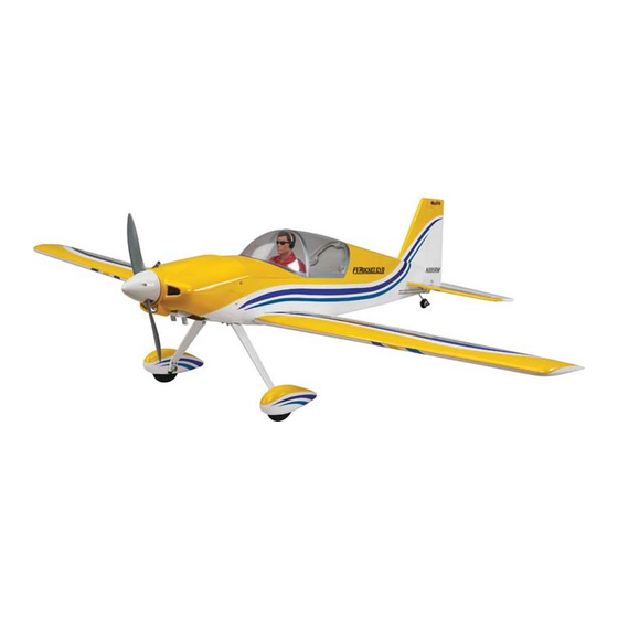
SPECIFICATIONS
Wingspan: 52 in [1320mm]
Length: 44 in [1120mm]
Weight: 6– 7 lb [2720– 3170 g]
2
Wing Area: 448 in
Wing Loading: 31 oz/ft
WARRANTY
Great Planes
Model Manufacturing Co. guarantees this kit to
®
be free from defects in both material and workmanship at the
date of purchase. This warranty does not cover any component
parts damaged by use or modification. In no case shall Great
Planes' liability exceed the original cost of the purchased kit.
Further, Great Planes reserves the right to change or modify this
warranty without notice.
In that Great Planes has no control over the final assembly or
material used for final assembly, no liability shall be assumed nor
accepted for any damage resulting from the use by the user of
the final user-assembled product. By the act of using the
user-assembled product, the user accepts all resulting liability.
If the buyer is not prepared to accept the liability associated
with the use of this product, the buyer is advised to return
READ THROUGH THIS MANUAL BEFORE STARTING CONSTRUCTION. IT CONTAINS IMPORTANT
INSTRUCTIONS AND WARNINGS CONCERNING THE ASSEMBLY AND USE OF THIS MODEL.
®
Entire Contents © 2013 Hobbico,
Inc. All rights reserved.
INSTRUCTION MANUAL
Radio: Four channel
2
[28.9 dm
]
2
2
[95 g /dm
]
(minimum)
with 5 servos
Electric Power: RimFire 55
this kit immediately in new and unused condition to the
place of purchase.
To make a warranty claim send the defective part or item to
Hobby Services at the address below:
Hobby Services
3002 N. Apollo Dr. Suite 1
Champaign IL 61822 USA
Include a letter stating your name, return shipping address, as
much contact information as possible (daytime telephone
number, fax number, e-mail address), a detailed description of
the problem and a photocopy of the purchase receipt. Upon
receipt of the package the problem will be evaluated as quickly
as possible.
airsupport@greatplanes.com
Engine: .46 -.55 cu in [7 – 9cc]
two-stroke,
.70 cu in [11.5cc]
four-stroke
Champaign, Illinois
(217) 398-8970, Ext 5
GPMA1030 Mnl
Advertisement
Table of Contents

Subscribe to Our Youtube Channel
Related Manuals for GREAT PLANES F1 Rocket Evo


Summary of Contents for GREAT PLANES F1 Rocket Evo
-
Page 1: Instruction Manual
3002 N. Apollo Dr. Suite 1 Champaign IL 61822 USA In that Great Planes has no control over the final assembly or material used for final assembly, no liability shall be assumed nor Include a letter stating your name, return shipping address, as... -
Page 2: Table Of Contents
For the latest technical updates or manual corrections FOLLOW THESE IMPORTANT SAFETY PRECAUTIONS to the F-1 Rocket visit the Great Planes web site at www. greatplanes.com. Open the “Airplanes” link, then select the F-1 1. Your F-1 Rocket should not be considered a toy, but rather Rocket ARF. -
Page 3: Decisions You Must Make
A LiPo compatible charger is required to charge the LiPo 7. WARNING: The cowl and wheel pants included in this kit battery. The Great Planes ElectriFly Triton2 EQ AC/DC Charger are made of fi berglass, the fi bers of which may cause eye, is designed for LiPo packs, but is also capable of charging skin and respiratory tract irritation. -
Page 4: Optional Supplies And Tools
To locate a hobby dealer, visit the Great Planes web site at www.greatplanes.com. Select “Where to Buy” in the menu ● Whenever just epoxy is specifi ed you may use either across the top of the page and follow the instructions provided 30-minute (or 45-minute) epoxy or 6-minute epoxy. -
Page 5: Kit Contents
Illinois and Nevada residents will also be charged sales tax. REPLACEMENT PARTS LIST ® ® If ordering via fax, include a Visa or MasterCard number Order No. Description and expiration date for payment. GPMA4320 Fuselage Mail parts orders Hobby Services GPMA4321 Wing and payments by... -
Page 6: Preparations
3/8" [2 x 10mm] washer head wood screw into each hole and PREPARATIONS back it out. Apply a drop of thin CA glue into each hole to ❏ harden the wood. When the CA glue has dried, thread a 5/64" 1. - Page 7 x 3/8" [2 x 10mm] washer head wood screw into each hole you drilled and back it out. Apply a drop of thin CA glue into each hole to harden the wood. When the CA glue has dried, thread a 5/64" x 3/8" [2 x 10mm] washer head screw into each of the four holes.
-
Page 8: Finish The Wing Panels
through the mounting holes in the control horn, drilling through the aileron. Insert a 5/64" x 5/8" [2x16mm] machine screw through the control horn and the aileron. Secure the horn by threading the screws into the nylon back plate, tightening it to the aileron. - Page 9 HOW TO CUT COVERING FROM BALSA Use a soldering iron to cut the covering from the stab. The tip of the soldering iron doesn’t have to be sharp, but a fi ne tip does work best. Allow the iron to heat fully. Use a straightedge to guide the soldering iron at a rate that will just melt the covering and not burn into the wood.
-
Page 10: Build The Fuselage
BUILD THE FUSELAGE It will be helpful in the assembly process to remove the canopy. To remove the canopy, slide it forward and lift the back of the canopy, removing it from the fuselage. Assemble the Tail Section ❏ 2. Use 30-minute epoxy to glue the stab into the fuselage. View the model and confi... -
Page 11: Install Landing Gear & Wheel Pants
Mark the location where the set screws make contact with the wire. File a fl at spot on the wire on the marks. Once completed, secure the tail wheel to the tail wheel assembly. Be sure that the tail wheel rotates freely on the axle. -
Page 12: Install The Servos And Pushrods
❏ ❏ 2.Install the 5/32 x 1-1/4" [32mm] axle into the landing gear 4. Slide the wheel pant over the wheel and secure the and secure it with the 5/16-24 [7.9mm] nut. Do this for both wheel pant to the landing gear with two 2-56 x 3/8" [9.5mm] landing gear legs. - Page 13 ❏ 4. Install the elevator and rudder servos into the servo tray in the direction shown using the hardware supplied with the servos. Be sure to harden the screw holes with thin CA as was done with the aileron servos. Cut three arms from two four-armed servo arms.
-
Page 14: Install The Power System
❏ 8. Though the engine has not been installed yet, determine which side of the fuselage to install the throttle servo based on the location of the throttle arm on the engine. Install the servo as shown using the hardware that came with the servo. Drill a 5/64"... - Page 15 tubing and clunks (fuel pickup) on the carb and fi ll lines should head will be on the right side. Test fi t your engine between almost reach the back of the tank but not touch. The clunks the mount halves. Slide the mount halves against the sides must be able to move freely inside the tank when assembled.
- Page 16 ❏ 9. Locate the plywood fuel tank stop. Glue it in place in the slots in the fuselage just behind the fuel tank. ❏ 10. Glue four 1/4" x 5/8" x 5/8" [6mm x15mm x15mm] cowl mounting blocks to the fuselage, two on each side as shown in the photo.
-
Page 17: Install The Electric Motor
one way the box can be assembled. Begin by gluing the two fi rewalls together. After the glue has cured install a blind nut into the each of the four holes on the backside of the fi rewall. ❏ 13. Thread a nylon clevis twenty turns onto the threaded end of the 2-56 x 15-3/4"... - Page 18 ❏ 7. Locate the 1/4" x1/4" x 2" [6mm x 6mm x 51mm] triangle stock. Cut off four 5/8" lengths and epoxy them to the fi rewall and the cowl mounting blocks as shown. ❏ 5. The fi rewall has eight cooling holes that need to be removed.
-
Page 19: Optional Method For Securing The Canopy
❏ 10. The batteries are mounted inside of the fuselage. In ❏ 1. Remove the canopy and you will see a blind nut on both the bottom of the fuselage install a strip of the self-adhesive sides of the fuselage where the canopy locking tabs extend Velcro, attaching the hook half of the material to the bottom into fuselage. - Page 20 ❏ 3. Remove the cowl. Apply a couple drops of thin CA into the holes in the cowl mounting blocks to harden the threads. Allow the glue to fully cure before re-installing the screws. ❏ 4. Re-install the carburetor to the engine. Slide the cowl over the engine, marking where the carburetor makes contact with the cowl.
-
Page 21: Complete The Radio Installation
Optional Receiver Battery Installation Location Complete the Radio Installation ❏ 1. Both sides of the fuselage have cut outs for the switch harness and charging jack. Determine which side of the fuselage you wish to mount the switch and charge jack (optional). -
Page 22: Finishing Touches
Even though the decals have a “sticky-back” and are not the water transfer type, submersing them in soap & water allows accurate positioning and reduces air bubbles underneath. ❏ 3. Position decal on the model where desired. Holding the decal down, use a paper towel to wipe most of the water away. ❏... -
Page 23: Check The Control Directions
4-CHANNEL RADIO SET UP (STANDARD MODE 2) These two 1500mAh batteries (both 11.1V) are being joined in PARALLEL. The result will be RUDDER RIGHT AILERON MOVES UP one 11.1V, 3000mAh battery. LEFT AILERON MOVES DOWN OKAY MOVES RIGHT 11.1V (3-Cell) 1500mAh 11.1V (3-Cell) 1500mAh... -
Page 24: Balance The Model (C.g.)
❏ OFFSET 1. If using a Great Planes C.G. Machine, set the rulers to 3 -1/4" [83 mm]. If not using a C.G. Machine, use a fi ne-point felt tip pen to mark lines on the top of wing on both sides of the fuselage 3 -1/4"... -
Page 25: Balance The Model Laterally
(ready to fl y) and an empty fuel tank, place always charge your transmitter and receiver batteries the night the model upside-down on a Great Planes CG Machine, or before you go fl ying, and at other times as recommended by lift it upside-down at the balance point you marked. -
Page 26: Ground Check And Range Check
Ground Check and Range Check AMA SAFETY CODE Run the engine for a few minutes to make sure it idles reliably, Read and abide by the following excerpts from the Academy transitions smoothly and maintains full power indefi nitely. of Model Aeronautics Safety Code. For the complete Safety Afterward, shut the engine off and inspect the model closely, Code refer to Model Aviation magazine, the AMA web site or making sure all fasteners, pushrods and connections have... -
Page 27: Checklist
❏ 12. Make sure there are silicone retainers on all the clevises CHECKLIST and that all servo arms are secured to the servos with the screws included with your radio. During the last few moments of preparation your mind may ❏... -
Page 28: Takeoff
or C.G. changes may be required to fi ne tune the model so it Identify which surface fl uttered (so the problem may fl ies the way you like. Mind your fuel/battery level, but use this be resolved) by checking all the servo grommets for fi...
Need help?
Do you have a question about the F1 Rocket Evo and is the answer not in the manual?
Questions and answers