Table of Contents
Advertisement
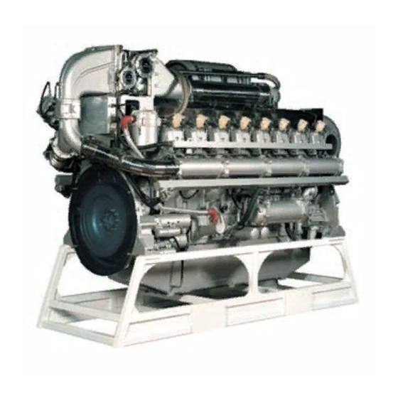
Perkins 4000 Series
Model 4016-E61TRS
USER'S HANDBOOK
Sixteen cylinder turbocharged gas engines
Publication TSL 4230E, Issue 4
© Proprietary information of Perkins Engines Company Limited, all rights reserved.
The information is correct at the time of print.
Published in December 2002 by Technical Publications,
Perkins Engines Company Limited, Stafford, ST16 3UB, England
i
This document has been printed from SPI². Not for Resale
Advertisement
Table of Contents

Related Manuals for Perkins 4016-E61TRS


Summary of Contents for Perkins 4016-E61TRS
- Page 1 USER’S HANDBOOK Sixteen cylinder turbocharged gas engines Publication TSL 4230E, Issue 4 © Proprietary information of Perkins Engines Company Limited, all rights reserved. The information is correct at the time of print. Published in December 2002 by Technical Publications, Perkins Engines Company Limited, Stafford, ST16 3UB, England...
- Page 2 This publication is divided into six chapters: 1 General information 2 Engine views 3 Operation instructions 4 Preventive maintenance 5 Gas and engine fluids specification 6 Fault diagnosis The following pages contain a detailed table of contents This document has been printed from SPI². Not for Resale...
-
Page 3: Table Of Contents
4016-E61TRS Contents 1 General information Introduction ..................1 Safety precautions .................. 2 How to care for your engine ... - Page 4 4016-E61TRS How to fill a radiator type cooling system ............20 4 Preventive maintenance Maintenance procedures ................. 21 Service schedule .
-
Page 5: General Information
General information Introduction The 4016-E61TRS is a 16 cylinder turbocharged engine designed by Perkins Engines Company Limited, a world leader in the design and manufacture of high-performance gas engines. Perkins approved assembly and quality standards, together with the latest technology, have been applied to the manufacture of your engine to give you reliable and economic power. -
Page 6: Safety Precautions
4016-E61TRS Safety precautions General For safe and reliable operation of the engine it is very important that these safety precautions, and those Warnings and Cautions given throughout this handbook, are observed, and where necessary the special tools indicated are used. - Page 7 4016-E61TRS Start-up l When working on the engine always ensure that the battery has been disconnected, and that any other means of accidental start-up has been disabled. l Never start the engine with the governor linkage disconnected. l Do not hold the stop lever in the run position when starting the engine.
- Page 8 4016-E61TRS Clothing l Do not wear loose clothing, ties, jewellery, etc. l Always wear steel toe cap shoes/boots. l Always wear the correct head, eye and ear protection. l Always wear suitable overalls. l Always replace a spillage contaminated overall immediately.
-
Page 9: How To Care For Your Engine
Company Limited and subject to oil analysis being performed at regular intervals. Refer to "Oil and filter change programme" on page 42. Ensure that all adjustments and repairs are done by personnel who have had the correct training. Perkins distributors have this type of personnel available. You can also obtain parts and service from your Perkins distributor. -
Page 10: Dangers From Used Engine Oils
4016-E61TRS Dangers from used engine oils Prolonged and repeated contact with mineral oil will result in the removal of natural oils from the skin, leading to dryness, irritation and dermatitis. The oil also contains potentially harmful contaminants which may result in skin cancer. -
Page 11: Danger From 'Fluorosilicone' (Viton) 'O' Ring Seals
4016-E61TRS Danger from ‘fluorosilicone’ (Viton) ‘O’ ring seals All of the engines ‘O’ ring seals are made from fluorosilicone material. It is a safe material under normal conditions of operation, but if it is burned the extremely dangerous hydroflouric acid is produced. -
Page 12: Engine Preservation
Local training for the correct operation, service and overhaul of engines is available at certain Perkins distributors. If special training is necessary, your Perkins distributor can advise you how to obtain it at the Perkins Customer Training Department or other main centres. -
Page 13: Service Tools
19 mm Combination spanner (rocker adjuster locknut) Feeler gauge set (to set bridge piece and valve clearance) Strap wrench (oil filter removal) 30 mm combination spanner (sump drain) Tool box Perkins supplied tools Part No Description 27610190 Spark plug removal tool... -
Page 14: Engine Identification
4016-E61TRS Engine identification The engine number and its build specification details are given on its data plate. The data plate is fastened to the crankcase above the flywheel housing on cylinder No. 8, ‘A’ Bank (A1). User’s Handbook, TSL 4230, Issue 4... -
Page 15: Engine Specifications
10 °C, then clean ‘soft’ water may be used, treated with 1% by volume of Perkins inhibitor (part number OE45350). Maximum jacket water pressure in crankcase ............2 bar Jacket water data: Coolant flow.. - Page 16 4016-E61TRS Lubrication system Recommended lubricating oil (for Natural Gas fuel applications) ......ESSO HPC 40 Lubricating oil capacity: Total system................... 286 litres Sump maximum .
- Page 17 4016-E61TRS Induction system Emissions data with combustion air temperature of 25 °C at continuous baseload rating. Emissions data Units TA-Luft TA-Luft Oxygen (O Oxides of nitrogen (NO mg/Nm Carbon monoxide (CO) mg/Nm 1100 Total hydrocarbons (THC) mg/Nm 1411 1372 (1) Figures corrected to 5% O in the exhaust stream.
-
Page 18: Performance Data
(surface radiation and other losses) Energy to charge cooler 2nd circuit Waste energy from exhaust gas Note: Not to be used for CHP design purposes. (Indicative figures only). Consult Perkins Engines Company Limited. Assumes complete combustion. User’s Handbook, TSL 4230, Issue 4... -
Page 19: Engine Views
4016-E61TRS Engine views Introduction Perkins engines are built for specific applications and the views which follow do not necessarily match your engine specification. ‘B’ Bank (gearcase end) ‘A’ Bank (flywheel end) User’s Handbook, TSL 4230, Issue 4 This document has been printed from SPI². Not for Resale... - Page 20 This page is intentionally blank This document has been printed from SPI². Not for Resale...
-
Page 21: Operating Instructions
Operating instructions Introduction Information for the mechanical maintenance of the 4016-E61TRS gas engine is given in this User’s Handbook (TSL 4230) and the Workshop Manual (TSL 4235). Information on the EMS system which controls all functions on the engine, including oil circuit priming, starting and stopping sequences is given in the OEM Application, Installation and Commissioning Manual (TSL 4232) and the Diagnostic Manual (TSL 4233) issue 3. -
Page 22: How To Fill The Engine With Oil
4016-E61TRS How to fill the engine with oil 1 Remove the sump drain plug and check that the sump is clean and empty. Refit and tighten the plug. Note: The oil filler and sump dipstick are at the front end of the engine, on the ‘B’ Bank side. -
Page 23: How To Fill A Chp Type Cooling System
4016-E61TRS How to fill a CHP type cooling system The siting of the cooling system filler cap and air vent plugs is dictated by each OEM’s individual installation. The operator must be aware of their position. Caution: All trapped air must be vented from the engines cooling system. If an airlock is present on engine start up localised overheating will occur, possibly causing engine damage. -
Page 24: How To Fill A Radiator Type Cooling System
4016-E61TRS How to fill a radiator type cooling system The siting of the cooling system air vent plugs is dictated by each OEMs individual installation. The operator must be aware of their position. Caution: All trapped air must be vented from the engines cooling system. If an airlock is present on engine start up localised overheating will occur, possibly causing engine damage. -
Page 25: Preventive Maintenance
4016-E61TRS Preventive maintenance Maintenance procedures The service schedule is suitable for an engine working under average conditions. If your engine is working under particularly dirty or dusty conditions, more frequent servicing will be necessary particularly in respect of the lubricating oil and air cleaners. -
Page 26: Service Schedule
4016-E61TRS Service schedule Oil and filter change intervals For engines running on gas to the specification given in "Gas specification" on page 41 and using the approved lubricating oil given in "Lubricating oil recommendations" on page 42, the oil and filters must be changed after the first 500 hours of operation. - Page 27 4016-E61TRS D service - 8,000 and 24,000 hours Description Manual Check EMS logged events and record Check EMS logged diagnostic codes, record and rectify Clean the filter gauze for the piston cooling jet oil gallery Equalise bridge pieces and set valve clearances...
- Page 28 4016-E61TRS F service - 12,000 and 28,000 hours Description Manual Check EMS logged events and record Check EMS logged diagnostic codes, record and rectify Clean the filter gauze for the piston cooling jet oil gallery Equalise bridge pieces and set valve clearances...
- Page 29 Notes: l Maintenance schedule from 32,000 hrs to 64,000 hrs is the same as 20,000 to 32,000 hrs. l At 64,000 hrs operation consult Perkins Engines Company Limited, Stafford, with reference to major overhaul and service exchange engine components. User’s Handbook, TSL 4230, Issue 4...
-
Page 30: How To Check The Lubricating Oil Level
4016-E61TRS How to check the lubricating oil level 1 Stop the engine and wait 5 minutes to allow the oil to drain into the sump. 2 Withdraw the dipstick and wipe clean. 3 Insert the dipstick and wait 2 seconds. -
Page 31: How To Change The Engine Oil And Filters
4016-E61TRS How to change the engine oil and filters 1 Place a container with a capacity of 250 litres (35 gal) under the sump drain plug. 2 Remove the sump drain plug and allow the oil to drain into the container. -
Page 32: How To Clean The Plug Filter Fitted In The Oil Gallery For The Piston Cooling Jets
4016-E61TRS How to clean the plug filter fitted in the oil gallery for the piston cooling jets 1 Remove the plug filter (A1). 2 Clean the filter using a suitable solvent, if necessary use compressed air to remove small particles from the gauze. -
Page 33: How To Check The Filter Restriction Indicator For The Closed Circuit Breather
4016-E61TRS How to check the filter restriction indicator for the closed circuit breather 1 Examine the clear plastic cover (A7) on the breather filter. If the red indicator button is not showing the filter is in serviceable condition. 2 When the filter reaches its contamination limit the red restriction indicator button will show. At this point the filter element must be renewed, see "To change the filter element of the closed circuit breather"... -
Page 34: To Change The Filter Element Of The Closed Circuit Breather
4016-E61TRS To change the filter element of the closed circuit breather 1 Disconnect the oil drain pipe (A1). 2 Release the three retaining clips (A2) and lift the filter container (A3) from the filter body. 3 Pull the filter element (A4) down from the filter body and discard it. -
Page 35: How To Check The Air Cleaner Restriction Indicator
4016-E61TRS How to check the air cleaner restriction indicator 1 Examine the middle section of the restriction indicator (A1). It will remain clear while the air cleaner is in serviceable condition. 2 When the filter reaches its contamination limit the restriction indicator will sense the change in manifold pressure and the middle section will change to red. -
Page 36: How To Change The Air Filter Element And Clean The Gas Mixer
4016-E61TRS How to change the air filter element and clean the gas mixer 1 Release the five over-centre catches (A1) and remove the air filter end cover (A2). 2 Pull out the filter element (A3). 3 Clean any dust accumulation from inside the air filter body and the gas mixer (A4) using a clean cloth. If necessary remove the coupling hose (A5) to give access. -
Page 37: How To Change The Oxygen Sensor
4016-E61TRS How to change the oxygen sensor 1 Disconnect the multi-pin plug (A1) on the oxygen sensor power cable from the connector on the oxygen sensor interface (A2). 2 Remove the oxygen sensor (A3) from the turbocharger outlet. 3 Fit the new oxygen sensor into the turbocharger outlet tighten it down to 25 Nm (18 lbf ft). -
Page 38: How To Remove A Spark Plug
4016-E61TRS How to remove a spark plug Special requirements Special tools Description Part number Spark plug removal socket and extension 27610190 1 Disconnect the power lead (A1) to the ignition coil. 2 Remove the two retaining nuts (A2). 3 Pull the combined ignition coil/plug cap (A3) out of the rocker cover. -
Page 39: How To Clean, Set And Fit A Spark Plug
4016-E61TRS How to clean, set and fit a spark plug Special requirements Special tools Description Part number Cylinder head spark plug thread cleaning 27610178 tool 1 Clean any carbon/ash deposits from the spark plug thread and ceramic insulator using a suitable solvent and a dry cloth. -
Page 40: Preparation For Equalising Bridge Pieces And Setting Valve Clearances
4016-E61TRS Preparation for equalising bridge pieces and setting valve clearances Special requirements Special tools Description Part number Engine cranking device SE253 1 Disconnect the power lead (A1) from the ignition coil. 2 Remove the two retaining nuts (A2). 3 Pull the combined ignition coil/plug cap (A3) out of the rocker cover. -
Page 41: Bridge Piece And Valve Clearance Setting Sequence
4016-E61TRS Bridge piece and valve clearance setting sequence T.D.C. Set bridge piece and valve Valves rocking on cylinder No. (Top Dead Centre) clearance on cylinder No. A1 - A8 B1 - B8 A3 - A6 B3 - B6 A7 - A2... -
Page 42: How To Equalise Bridge Pieces
4016-E61TRS How to equalise bridge pieces 1 Rotate the engine to the position given in "Bridge piece and valve clearance setting sequence" on page 37. Caution: Check the inlet and exhaust rockers have clearance on the bridge piece. 2 Loosen the locknut on the bridge piece (A1). -
Page 43: How To Set Valve Clearances
4016-E61TRS How to set valve clearances Special requirements Special tools Description Part number Feeler gauges 1 Check the clearance using a feeler gauge. Note: The inlet and exhaust valve clearance is 0,4 mm (0.016 in). 2 To set the valve clearance loosen the locknut (A2). -
Page 44: How To Check Valve And Seat Recession
3 To check the exhaust valve, place the tool around bolt (A2). Note: As a result of product improvements, the rocker box to cylinder head joint has been improved using a graphite material which is 0,7 mm thicker than the joint it has replaced. This change covers all 4016-E61TRS engines. -
Page 45: Gas And Engine Fluids Specification
(930 BTU/Sft Also pressure must be constant to maintain emissions and stability. If any of the above parameters are not met, Perkins Engines Company Limited should be consulted for advice. Gas safety regulations There are legal requirements that within the U.K. gas fittings and equipment must be installed only by competent persons and in accordance with the Institution of Gas Engineers Procedures IGE UP2. -
Page 46: Lubricating Oil Recommendations
Approved lubricating oil Esso Estor HPC 40 Caution: To use a lubricating oil other than that specified, it is essential that Perkins Engines Company Limited, Stafford, is consulted, failure to do so could affect the engine warranty. Oil and filter change programme The lubricating oil and filter life is governed by the engine load and gas quality. -
Page 47: Coolant Specification
For combined heat and power systems and where there is no likelihood of ambient temperatures below 10 °C, then clean ‘soft’ water may be used, treated with 1% by volume of Perkins inhibitor. The inhibitor is available under Perkins part number OE45350. - Page 48 This page is intentionally blank This document has been printed from SPI². Not for Resale...
-
Page 49: Fault Diagnosis
4016-E61TRS Fault diagnosis Introduction This fault diagnosis chart covers mechanical defects which may occur with the engine. It must be used in conjunction with electronic service tools (TIPSS-EST). To locate problems within the engine and its systems, refer to the Diagnostic Manual (TSL 4233). -
Page 50: Problems And Possible Causes
4016-E61TRS Problems and possible causes Problem Possible causes The starter motor turns the engine too slowly 1, 2, 3, 4 The engine does not start 5, 6, 7, 8, 10, 11, 12, The engine is difficult to start 5, 7, 8, 9, 10, 11, 12, 26, 27, 28, 29, 46, 47... - Page 51 4016-E61TRS List of possible causes 1 Battery capacity low. 2 Bad electrical connections. 3 Fault in starter motor. 4 Wrong grade of lubricating oil. 5 Starter motor turns engine too slowly. 6 Ignition failed (no spark at plugs). 7 Dirty or worn spark plugs.
- Page 52 4016-E61TRS 41 Restriction in coolant passages on the engine. 42 Spare. 43 Restriction in sump strainer. 44 Turbocharger impeller is damaged or dirty. 45 Lubricating oil seal of turbocharger leaks. 46 Faulty engine management system. 47 Faulty sensor. 48 Oil cooler tubestack blocked.
Need help?
Do you have a question about the 4016-E61TRS and is the answer not in the manual?
Questions and answers