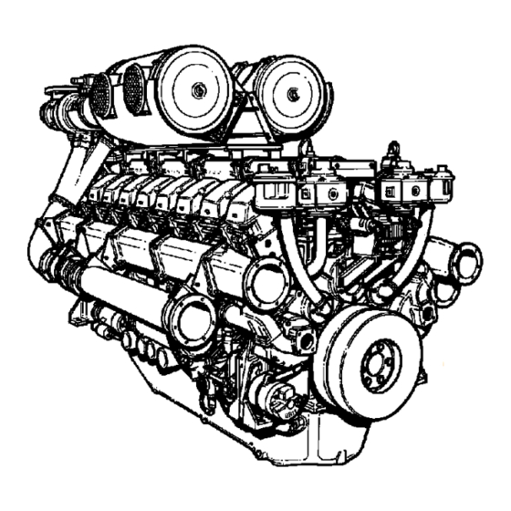
Perkins 400 Series Operation And Maintenance Manual
Industrial engine
Hide thumbs
Also See for 400 Series:
- User handbook manual (76 pages) ,
- Operation and maintenance manual (80 pages) ,
- Operation and maintenance manual (100 pages)


Need help?
Do you have a question about the 400 Series and is the answer not in the manual?
Questions and answers