
Subscribe to Our Youtube Channel
Related Manuals for Perkins 4016-61TRS1


Summary of Contents for Perkins 4016-61TRS1
- Page 1 SEBU8430-00 August 2008 Operation and Maintenance Manual 4016-61TRS1 and 4016-61TRS2 Gas Engines G16 (Engine)
-
Page 2: Important Safety Information
These changes can affect the service that is given to the product. Obtain the complete and most current information before you start any job. Perkins dealers or Perkins distributors have the most current information available. When replacement parts are required for this product Perkins recommends using Perkins replacement parts. -
Page 3: Table Of Contents
SEBU8430 Table of Contents Table of Contents Index Section Index ..............69 Foreword ..............4 Safety Section Safety Messages ............ 5 General Hazard Information ........7 Burn Prevention ............9 Fire Prevention and Explosion Prevention ....9 Crushing Prevention and Cutting Prevention ..11 Mounting and Dismounting ........ -
Page 4: Foreword
They assist with developing the skills and Perkins authorized personnel. Your Perkins dealer techniques required to operate the engine more or your Perkins distributor offers a variety of options efficiently and economically. Skill and techniques regarding overhaul programs. If you experience... -
Page 5: Safety Section
Replace any warning sign that is damaged or missing. If a warning sign is attached to a part of the engine that is replaced, install a new warning sign on the replacement part. Your Perkins dealer or your distributor can provide new warning signs. - Page 6 SEBU8430 Safety Section Safety Messages (1) Engine Oil Level g01241033 Illustration 2 Typical example The warning label for checking the engine oil Level The Universal Warning label (2) is located on the (1) is located on the inlet manifold on the left side of inlet manifold on the right side of the engine.
-
Page 7: General Hazard Information
SEBU8430 Safety Section General Hazard Information (3) Engine Derate g01241021 Illustration 4 Typical example The warning label for derating engine information Engine exhaust contains products of combustion (3) is located on the control box. Refer to OEM which may be harmful to your health. Always start the information for the location of the control box. -
Page 8: Pressurized Air And Water
SEBU8430 Safety Section General Hazard Information Pressurized Air and Water Pressurized air and pressurized water can cause debris and/or hot water to be blown out. This could result in personal injury. When pressurized air and/or pressurized water is used for cleaning, wear protective clothing, protective shoes, and eye protection. -
Page 9: Burn Prevention
SEBU8430 Safety Section Burn Prevention Dispose of Waste Properly Oils Hot oil and hot lubricating components can cause personal injury. Do not allow hot oil or hot components to contact the skin. If the application has a makeup tank, remove the cap for the makeup tank after the engine has stopped. - Page 10 Personal injury, property damage, or engine damage could result. If the application involves the presence of combustible gases, consult your Perkins dealer for additional information about suitable protection devices. All local regulations must be observed.
-
Page 11: Crushing Prevention And Cutting Prevention
Crushing Prevention and Cutting Prevention Repair any lines that are loose or damaged. Leaks i02453744 can cause fires. Consult your Perkins dealer for Mounting and Dismounting repair or for replacement parts. Check lines, tubes and hoses carefully. Do not use your bare hand to check for leaks. -
Page 12: Engine Starting
SEBU8430 Safety Section Engine Starting All protective guards and all protective covers must i00659907 be installed if the engine must be started in order Engine Stopping to perform service procedures. To help prevent an accident that is caused by parts in rotation, work around the parts carefully. - Page 13 SEBU8430 Safety Section Electrical System g01217202 Illustration 11 Typical example (1) Starting motor to ground (2) Battery negative to engine Correct grounding for the engine electrical system is necessary for optimum engine performance and reliability. Incorrect grounding will result in uncontrolled electrical circuit paths and in unreliable electrical circuit paths.
-
Page 14: Product Information Section
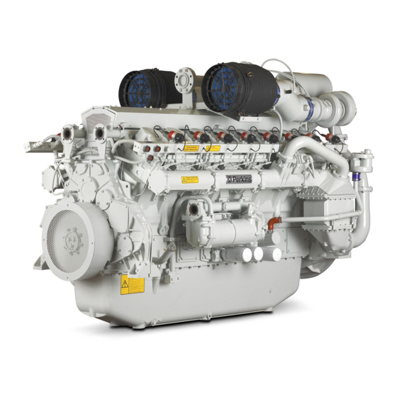
SEBU8430 Product Information Section Model Views and Specifications Product Information Section Model Views and Specifications i02885828 Model View Illustrations The illustrations show various typical features of 4016 Series TRS Engine. The illustrations do not show all of the options that are available. g01525185 Illustration 12 Typical example... -
Page 15: Product Description
This mixture is compressed by the turbocharger. The mixture passes through the tumbulator, and the charge coolers, and into the inlet manifolds. The The Perkins Engines were developed in order to speed and the load is governed by electronically provide gas engines for generator set applications. - Page 16 SEBU8430 Product Information Section Model Views and Specifications • Voltage The system is used when recovery of heat is not an important factor. • Duration of the spark Cogeneration engine • Ignition timing Cogeneration uses energy from heat which would •...
- Page 17 SEBU8430 Product Information Section Model Views and Specifications Table 1 4016 Engine Specifications Rated rpm 1500 Number of Cylinders Configuration Vee-form Bore 160 mm (6.299 inch) Stroke 190 mm (7.480 inch) Displacement 61.123 L (3729.954 in Compression ratio 13:1 Aspiration Turbocharged Rotation (flywheel end) Counterclockwise...
-
Page 18: Product Identification Information
Number of Cylinders i02978102 Plate Locations and Film Locations Perkins dealers and Perkins distributors require all of these numbers in order to determine the components that were included in the engine. This permits Engine Identification accurate identification of replacement part numbers. - Page 19 SEBU8430 Product Information Section Product Identification Information g01229580 Illustration 16 The location of the serial number plate for vee-form engines The serial number plate (1) on a vee-form engine is located on the rear face of the cylinder block (bank A).
-
Page 20: Operation Section
fixtures obsolete. If alterations are made, ensure Product Lifting that correct lifting devices are provided. Consult your Perkins dealer or your Perkins distributor for information regarding fixtures for correct engine lifting. NOTICE Never bend the eyebolts and the brackets. Only load i03139740 the eyebolts and the brackets under tension. -
Page 21: Gauges And Indicators
Determine and correct the cause of any significant change in the readings. Consult your Perkins dealer or your Perkins distributor for assistance. NOTICE If no oil pressure is indicated, STOP the engine. If maximum coolant temperature is exceeded, STOP the engine. -
Page 22: Features And Controls
SEBU8430 Operation Section Features and Controls Features and Controls i02894958 Sensors and Electrical Components i02885816 Performance Parameters Electronic Ignition System (EIS) Air/Fuel Ratio The Electronic Ignition System includes the following components: The correct air/fuel ratio is very important for the following considerations: •... - Page 23 SEBU8430 Operation Section Features and Controls Governor Engines may be equipped with optional engine protective devices that are not included in this section. This section contains some general information about The engine is installed with a digital governor that the function of typical engine protective devices. includes the following components: •...
-
Page 24: Control Panel
SEBU8430 Operation Section Features and Controls NOTICE During testing, abnormal operating conditions must be simulated. The tests must be performed correctly in order to pre- vent possible damage to the engine. Periodic testing of engine protective devices for proper operation is recommended maintenance. To prevent damage to the engine, only authorized service personnel should perform the tests. -
Page 25: Engine Starting
SEBU8430 Operation Section Engine Starting Engine Starting • Observe the air cleaner service indicator. Service the air cleaner when the diaphragm enters the red zone, or when the red piston locks in the visible position. i02894959 Before Starting Engine • Remove any electrical loads. - Page 26 SEBU8430 Operation Section Engine Starting 5. Stop the engine and check the engine oil and the engine coolant level. NOTICE For initial start-up of a new or rebuilt engine, and for 6. Operate the engine under normal working start-up of an engine that has been serviced, make conditions.
-
Page 27: After Starting Engine
SEBU8430 Operation Section Engine Starting 2. Check that the gas pressure is in limits. If the gas i02978143 pressure is incorrect a warning is activated and After Starting Engine the electrical system will shut down. If the gas pressure is in limits, go to the next step. 3. -
Page 28: Engine Operation
SEBU8430 Operation Section Engine Operation Engine Operation i02894963 Engine Operation Proper operation and maintenance are key factors in attaining the maximum service life and economy for the engine. Follow the instructions in this Operation and Maintenance Manual and Systems Operation, Testing and Adjusting in order to minimize operating costs and maximize the service life of the engine. -
Page 29: Engine Stopping
SEBU8430 Operation Section Engine Stopping Engine Stopping i02453745 Manual Stop Procedure i02978181 Emergency Stopping In order to manually stop the engine, refer to the OEM for information. The procedure will depend on the system that has been installed. The OEM will supply the system. NOTICE In the event of an emergency or in the event of an Stopping the engine immediately after the engine has... -
Page 30: Maintenance Section
For a list of recommended lubricating oils, refer to the latest issue of Perkins service bulletin 48. NOTICE Oil analysis Frequently check the specific gravity of the coolant for proper freeze protection or for anti-boil protection. -
Page 31: Coolant Recommendations
Table 5 • Acceptable Water Cavitation of the water pump Property Maximum Limit For optimum performance, Perkins recommends a 1:1 mixture of a water/glycol solution. Chloride (Cl) 40 mg/L Sulfate (SO 100 mg/L Note: Use a mixture that will provide protection... - Page 32 Heavy-duty diesel engines _________ ___________________________ specification for coolant specification • Automotive applications The following two coolants are used in Perkins diesel engines: The anti-corrosion package for ELC is different from the anti-corrosion package for other coolants. ELC Preferred – Perkins ELC is an ethylene glycol base coolant.
-
Page 33: Elc Cooling System Cleaning
8. Repeat Steps 6 and 7 until the system is To change from heavy-duty antifreeze to the Perkins completely clean. ELC, perform the following steps: 9. Fill the cooling system with the Perkins Premixed NOTICE ELC. Care must be taken to ensure that all fluids are... - Page 34 SCA that is needed. intervals. Use the equation that is in Table 12 to determine the Refer to Table 9 for part numbers and for quantities amount of Perkins SCA that is required, if necessary: of SCA. Table 12 Table 9...
- Page 35 Maintenance Section Refill Capacities Cleaning the System of Heavy-Duty 4016-61TRS Antifreeze Table 15 Perkins cooling system cleaners are designed 4016-61 TRS Refill Capacities to clean the cooling system of harmful scale and corrosion. Perkins cooling system cleaners Compartment or System...
-
Page 36: Maintenance Interval Schedule
Every 1000 Service Hours powered by natural gas only. For other gases, consult Engine - Clean ............44 Perkins Applications Engineering (Stafford ) for more Engine Valve Lash and Bridge - Adjust ....52 information. Every 1000 Service Hours or 1 Year When Required Crankshaft Vibration Damper - Inspect .... -
Page 37: Initial 100 Service Hours Alternator Pulley - Check
Personal injury can result without following prop- er procedure. When using pressure air, wear a pro- Perkins recommends a scheduled inspection of tective face shield and protective clothing. the alternator. Inspect the alternator for loose connections and correct battery charging. Check the... -
Page 38: Battery - Replace
SEBU8430 Maintenance Section Battery - Replace i02429553 Battery - Replace Batteries give off combustible gases which can explode. A spark can cause the combustible gas- es to ignite. This can result in severe personal in- jury or death. Ensure proper ventilation for batteries that are in an enclosure. -
Page 39: Every 500 Service Hours Or 1 Year Battery Electrolyte Level - Check
SEBU8430 Maintenance Section Battery Electrolyte Level - Check i02747977 i03104621 Battery Electrolyte Level - Belts - Inspect/Adjust/Replace Check (Alternator Belt) When the engine is not run for long periods of time or Inspection when the engine is run for short periods, the batteries may not fully recharge. -
Page 40: Cooling System Coolant - Change
SEBU8430 Maintenance Section Carburetor Air/Fuel Ratio - Check/Adjust 6. Restore the electrical supply to the engine. 4. Check the tension of the belt. Refer to “Inspection” for the correct procedure. Adjustment 5. If necessary, restore the electrical supply to the engine and install the guards. - Page 41 Note: The cooling system must be filled slowly. Refer Charge Water System Fill to Perkins Engines Stafford for more information. 1. Close the drain cock or install the drain plug on Note: The cooling system must be filled slowly. Refer the radiator or the heat exchanger.
-
Page 42: Cooling System Coolant Level - Check
Refer to the Operation and Maintenance Manual, “Fluid recommendations”.Perkins POWERPART antifreeze with a concentration of 50% will give protection against frost to a temperature of −35 °C (−31 °F). -
Page 43: Every 1000 Service Hours Or 1 Year Crankshaft Vibration Damper - Inspect
If the temperature begins to rise, reduce the interval for inspecting the damper. If the temperature of the damper reaches 100 °C (212 °F), consult your Perkins dealer. Inspect the damper for evidence of dents, cracks, and leaks of the fluid. -
Page 44: Driven Equipment - Inspect/Replace/Lubricate
Perform any maintenance that is recommended documentation or video documentation is also by the OEM of the driven equipment. Refer to the recommended. Consult your Perkins dealer for literature of the OEM of the driven equipment for the information on available borescopes. -
Page 45: Engine Air Cleaner Service Indicator - Inspect
SEBU8430 Maintenance Section Engine Air Cleaner Element - Replace A clean engine provides the following benefits: • Easy detection of fluid leaks • Maximum heat transfer characteristics • Ease of maintenance i02947520 Engine Air Cleaner Element - Replace NOTICE Never run the engine without an air cleaner element installed. -
Page 46: Engine Crankcase Breather - Clean/Replace
SEBU8430 Maintenance Section Engine Crankcase Breather - Clean/Replace Observe the service indicator. Replace the air filter element if the indicator is triggered by the following event: • The red piston locks in the visible position. Test the Service Indicator Service indicators are important instruments. g01224945 Illustration 31 Typical example... -
Page 47: Engine Crankcase Breather - Clean/Replace
SEBU8430 Maintenance Section Engine Crankcase Breather - Clean/Replace i02978569 Engine Crankcase Breather - Clean/Replace Closed Breather System Ensure that the power supply is disconnected from the engine. g01235923 Illustration 33 Typical example 3. Install the new filter element. Align the clips (1). Install the bowl (2). -
Page 48: Engine Oil Filter (Auxiliary) - Change
SEBU8430 Maintenance Section Engine Oil - Change i02888179 Engine Oil - Change Note: Refer to the Operation and Maintenance Manual, “Engine Oil Sample - Obtain” before performing maintenance. Do not drain the engine lubricating oil when the engine is cold. As the engine lubricating oil cools, suspended waste particles settle on the bottom of the oil pan. -
Page 49: Engine Oil Filter - Change
Part Tool Part Name Number Strap Wrench NOTICE Perkins oil filters are manufactured to Perkins Engine g01233078 Illustration 36 Company LTD specifications. Use of an oil filter that is Typical example not recommended by Perkins Engine Company LTD could result in severe damage to the engine. Large The changeover valve (1) has three positions. -
Page 50: Engine Oil Level - Check
SEBU8430 Maintenance Section Engine Oil Level - Check 3. Lubricate the sealing rings (2) with clean engine oil. 4. Install the new oil filters (1). Note: Apply hand pressure only in order to tighten the oil filters. Fill the Oil Pan Refer to Operation and Maintenance Manual, “Fluid Recommendations”... -
Page 51: Engine Protective Devices - Check
Iron - Fe less than 20 ppm • Copper - Cu less than 40 ppm Ensure that all power is disconnected to the engine before performing these procedures. Note: Perkins Engines Stafford must agree to the maintenance schedule. Table 17 Required Tools Part... -
Page 52: Engine Valve Lash And Bridge - Adjust
SEBU8430 Maintenance Section Engine Valve Lash and Bridge - Adjust Speed Sensor g01554776 Illustration 40 g01234089 Typical example Illustration 39 Typical example 2. Remove the sensor (2). Clean any debris from the sensor. 1. Remove the connection (3). Loosen the locknut (1). - Page 53 SEBU8430 Maintenance Section Engine Valve Lash and Bridge - Adjust Monitoring the Valve Recession The recorded values can be used to identify any excessive valve seat wear on individual valves. The Table 18 recorded values can be used to schedule a top end overhaul.
-
Page 54: Valve Lash
SEBU8430 Maintenance Section Engine Valve Lash and Bridge - Adjust 3. Ensure that there is clearance between the rocker arm and bridge pad. g01235020 Illustration 41 Typical example g01235021 Illustration 43 1. Remove the spark plug. Refer to this Typical example manual, “Ignition System Spark Plugs - Check/Adjust/Replace”. -
Page 55: Exhaust Piping - Inspect
• Leaks 3. Tighten the grub screws (2) to a torque of 90 N·m (66 lb ft). • Loose connections 4. Install the guards (not shown). Consult your Perkins dealer for assistance. 5. Restore the electrical supply to the engine. -
Page 56: Fuel Filtration System - Service
SEBU8430 Maintenance Section Fuel Filtration System - Service i02478666 NOTICE Fuel Filtration System - Service Do not bend or strike high pressure lines. Do not in- stall bent or damaged lines, tubes or hoses. Repair any loose or damaged fuel and oil lines, tubes and hoses. -
Page 57: Ignition System Spark Plugs - Inspect/Replace
SEBU8430 Maintenance Section Ignition System Spark Plugs - Inspect/Replace 2. Loosen the cooling system filler cap slowly in order to relieve any pressure. Remove the cooling system filler cap. Note: Drain the coolant into a suitable, clean container. The coolant can be reused. 3. -
Page 58: Jacket Water Heater - Check
SEBU8430 Maintenance Section Ignition System Timing - Check/Adjust 4. Install the cap when the ignition timing is correct. i02887641 Remove the timing light. Ignition System Timing - Check/Adjust • Rotating the screw (1) clockwise retards the ignition timing. • Rotating the screw (1) counterclockwise advances the ignition timing. -
Page 59: Overhaul (In-Frame)
Those components are i02895045 replaced, if necessary. Overhaul (In-Frame) Your Perkins dealer can provide these services and components. Your Perkins dealer can ensure that the components are operating within the appropriate specifications. Scheduling an In-Frame Overhaul... -
Page 60: Major Overhaul Information
• Oil cooler If you elect to perform an overhaul without the • Pistons services of a Perkins dealer, be aware of the following recommendations. • Ignition coils Replacing of Components • Valve train that includes the rocker gear Replace the following components during the major overhaul. -
Page 61: Overhaul Considerations
SEBU8430 Maintenance Section Overhaul Considerations • 1. Remove the valve mechanism covers from all Cleaning of the internal passages of the engine cylinders. and the engine block 2. Remove the bridge assembly for all the inlet It is not practical to wait until the engine exhibits valves. -
Page 62: Radiator - Clean
Inspect these items for good condition: reduction of engine efficiency. welds, mounting brackets, air lines, connections, clamps, and seals. Make repairs, if necessary. Your Perkins dealer can provide the parts that are needed to rebuild the engine at the least possible i02885745 cost. -
Page 63: Water Temperature Regulator - Replace
Visually inspect the elements for damage. Refer to the latest issue of Perkins service bulletin 1. Fill a suitable container with coolant. Place the 157 for more information on inspecting the water element in the container. - Page 64 SEBU8430 Maintenance Section Water Temperature Regulator - Replace Note: If the valve (1) is open at ambient temperature the elements must be renewed. g01240533 Illustration 50 Typical example 2. Heat the coolant gradually. Use a thermometer (2) in order to check the temperature of the coolant. g01240519 Illustration 51 The opening temperature of the valve is 71 °C...
-
Page 65: Reference Information Section
Maintenance records are a key element of a maintenance program that is well managed. Accurate maintenance records can help your Perkins dealer to fine tune the recommended maintenance intervals in order to meet the specific operating situation. This should result in a lower engine operating cost. -
Page 66: Maintenance Log
SEBU8430 Reference Information Section Reference Materials i02481255 Maintenance Log Table 24 Engine Model Customer Identifier Serial Number Arrangement Number Service Quantity Service Item Date Authorization Hours Of Fuel... - Page 67 SEBU8430 Reference Information Section Reference Materials i02885832 Valve Data Sheet Table 25 Engine Model Serial Number Service Hours Cylinder Valve Location Current Cylinder Reset size Wear Pressure Measure Inlet Inlet Exhaust Exhaust Inlet Inlet Exhaust Exhaust Inlet Inlet Exhaust Exhaust Inlet Inlet Exhaust...
-
Page 68: Warranty Information
Exhaust Inlet Exhaust Exhaust i02885737 Warranty Information The engine installation and the service interval for the engine must be approved. The engine must be operated with the approved fuel, lubricant and coolant. Refer to Perkins Engines Stafford for more information. -
Page 69: Index
SEBU8430 Index Section Index Emergency Stopping ..........29 Typical Procedure in Order to Stop the Engine .. 29 Engine - Clean............44 After Starting Engine ..........27 After Stopping Engine..........29 Engine Air Cleaner Element - Replace....45 Aftercooler Core - Inspect/Clean (Air Charge Engine Air Cleaner Service Indicator - Inspect.. - Page 70 SEBU8430 Index Section Overhaul (Major)............ 59 Fuel Filtration System - Service......56 Fuel System Fuel Filter Differential Pressure - Major Overhaul Information ....... 60 Check..............56 Scheduling a Major Overhaul......59 Overhaul (Top End) ..........60 Scheduling a Top End Overhaul ......60 Overhaul Considerations ........
- Page 71 SEBU8430 Index Section Starting the Engine ..........25 Automatic Starting..........27 Engine Starting Procedure......... 26 Final Checks and First Engine Start ....26 Manual starting ..........27 Operation of the Generator Set Control Panel... 27 Purging Unburned Gas ........26 Starting with Jump Start Cables ......
- Page 72 SEBU8430 Index Section...
- Page 73 Product and Dealer Information Note: For product identification plate locations, see the section “Product Identification Information” in the Operation and Maintenance Manual. Delivery Date: Product Information Model: Product Identification Number: Engine Serial Number: Transmission Serial Number: Generator Serial Number: Attachment Serial Numbers: Attachment Information: Customer Equipment Number: Dealer Equipment Number:...
- Page 74 Copyright © 2008 Perkins Engines Company Limited Printed in U.K. All Rights Reserved...
Need help?
Do you have a question about the 4016-61TRS1 and is the answer not in the manual?
Questions and answers