
Related Manuals for Perkins 4016-61 TRG


Summary of Contents for Perkins 4016-61 TRG
- Page 1 SEBU8604-02 (en-us) October 2022 Operation and Maintenance Manual 4016-61 TRG Industrial Engine...
- Page 2 If a tool, procedure, work method or operating technique that is not specifically recommended by Perkins is used, you must satisfy yourself that it is safe for you and for others. You should also ensure that you are authorized to perform this work, and that the product will not be damaged or become unsafe by the operation, lubrication, maintenance or repair procedures that you intend to use.
-
Page 3: Table Of Contents
SEBU8604-02 Table of Contents Table of Contents Refill Capacities..........41 Maintenance Interval Schedule (Engines in Foreword ............4 Base Load Applications)........ 49 Safety Section Maintenance Interval Schedule (Engines in Standby Applications)........51 Safety Messages..........6 Maintenance Interval Schedule (Engines in Additional Messages ........11 Prime Power Applications) ...... -
Page 4: Foreword
State of arises regarding your engine, or this manual, please California to cause cancer, birth defects, consult with your Perkins dealer or your Perkins distributor for the latest available information. and other reproductive harm. WARNING – This product can... - Page 5 Perkins distributor offers various options regarding overhaul programs. If you experience a major engine failure, there are also numerous after failure overhaul options available. Consult with your Perkins dealer or your Perkins distributor for information regarding these options.
-
Page 6: Safety Section
Replace any warning sign that is damaged or missing. If a warning sign is attached to a part of the engine that is replaced, install a new warning sign on the replacement part. Your Perkins dealer or your Perkins distributor can provide new warning signs. - Page 7 SEBU8604-02 Safety Section Safety Messages Warning Labels Position Bank A Illustration 1 g06595920 Typical example (1) Universal warning (3) Hot surface warning (5) Ether warning (2) No step warning (4) Hot fluid under pressure warning...
- Page 8 SEBU8604-02 Safety Section Safety Messages Warning Labels Position Bank B Illustration 2 g06595921 Typical example (1) Universal warning (3) Ether warning (5) Hot surface warning (2) No step warning (4) Hot fluid under pressure warning...
- Page 9 SEBU8604-02 Safety Section Safety Messages Warning Label Front View Do not operate or work on this equipment unless you have read and understand the instructions and warnings in the Operation and Maintenance Manuals. Failure to follow the instructions or heed the warnings could result in serious injury or death.
- Page 10 SEBU8604-02 Safety Section Safety Messages The ether warning labels are on both the The hot surface warning labels are on the oil coolers aftercoolers. that are on both banks of the engine. Do Not Step Hot Fluid Under Pressure Illustration 6 g01393287 Illustration 8 g01371640...
-
Page 11: Additional Messages
SEBU8604-02 Safety Section Additional Messages The hot fluids under pressure labels are on the oil The rotating shaft hand crush hazard label (6) is on coolers that are on both banks of the engine. the cover of the crankshaft vibration damper guard. 6 Rotating Shaft Hand Crush i07199910 Hazard... - Page 12 SEBU8604-02 Safety Section General Hazard Information Do not allow unauthorized personnel on the engine, • Do not attempt any repairs or any adjustments to or around the engine when the engine is being the engine while the engine is operating. serviced.
- Page 13 SEBU8604-02 Safety Section General Hazard Information The maximum air pressure for cleaning purposes must be below 205 kPa (30 psi). The maximum water pressure for cleaning purposes must be below 275 kPa (40 psi). Fluid Penetration Pressure can be trapped in the hydraulic circuit long after the engine has been stopped.
- Page 14 Hexavalent Chromium Perkins equipment and replacement parts comply with applicable regulations and requirements where originally sold. Perkins recommends the use of only genuine Perkins replacement parts. Hexavalent chromium has occasionally been detected on exhaust and heat shield systems on Perkins engines.
-
Page 15: Burn Prevention
• Wear an approved respirator if there is no other good hygiene, and adhering to safe work practices way to control the dust. when handling the equipment or parts. Perkins also recommends the following: • Comply with applicable rules and regulations for the work place. -
Page 16: Fire Prevention And Explosion Prevention
SEBU8604-02 Safety Section Fire Prevention and Explosion Prevention After the engine has stopped, you must wait for 60 • Ensure that the components have cooled. seconds to allow the fuel pressure to be purged from • Use Neoprene gloves and discard the gloves the high-pressure fuel lines before any service or repair is performed on the engine fuel lines. - Page 17 If the application involves the presence of combustible gases, consult your Perkins dealer and/ or your Perkins distributor for additional information about suitable protection devices. Remove all flammable combustible materials or conductive materials such as fuel, oil, and debris from the engine.
-
Page 18: Crushing Prevention And Cutting Prevention
Do not bend high-pressure lines. Do not strike high- pressure lines. Do not install any lines that are damaged. Leaks can cause fires. Consult your Perkins distributor for replacement parts. Replace the parts if any of the following conditions are present: •... -
Page 19: Mounting And Dismounting
SEBU8604-02 Safety Section Mounting and Dismounting i05875651 i06545901 Mounting and Dismounting Engine Starting Do not climb on the engine. The engine has not been designed with mounting or dismounting locations. Do not use aerosol types of starting aids such as Refer to the OEM for the location of foot and hand ether. -
Page 20: Electrical System
The operating parameters for the governor should only be Uncontrolled electrical circuit paths can result in modified by a trained Perkins representative. Refer to damage to main bearings, to crankshaft bearing the Special Instruction, “Pandoras Digital Governor”... -
Page 21: Product Information Section
SEBU8604-02 Product Information Section General Information Product Information Section General Information i02640420 Welding on Engines with Electronic Controls NOTICE Proper welding procedures are necessary in order to avoid damage to the engine's ECM, sensors, and as- sociated components. When possible, remove the component from the unit and then weld the compo- nent. -
Page 22: Model Views
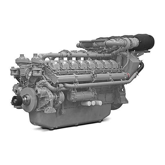
SEBU8604-02 Product Information Section Model Views Model Views i03754000 Model View Illustrations 4016-61TRG The following model views show typical features of the engine. Due to individual applications, engines may appear different from the Illustrations. Note: Only serviced components are identified on the following Illustrations. - Page 23 SEBU8604-02 Product Information Section Model View Illustrations Illustration 20 g02029553 Left side view of engine (1) Engine crankcase breather (A Bank) (5) Engine crankcase breather (B Bank) (9) Oil level gauge (Dipstick) (2) Thermostat housing (A Bank) (6) Air shutoff valve (B Bank) (10) Oil filler (3) Electronic governor actuator (7) 3x Oil filters (B Bank)
- Page 24 A cylinders are on the right hand side of the engine. Bank B cylinders are on the left hand side of the The 4016-61 TRG engine model is designed for engine. To determine the left and right sides of the power generation.
- Page 25 Refer to this Operation and Maintenance Manual, “Maintenance Interval Schedule” for more information on maintenance items. Illustration 22 g01210841 4016-61 TRG engine model (A) Bank (B) Bank (X) Inlet valves (Y) Exhaust valves Table 1...
-
Page 26: Product Identification Information
Number of Cylinders Information i08246226 Plate Locations and Film Locations Perkins dealers and Perkins distributors require all of these numbers to determine the components that were included in the engine. This permits accurate Engine Identification identification of replacement part numbers. - Page 27 SEBU8604-02 Product Information Section Plate Locations and Film Locations Illustration 24 g02029586 Typical example The serial number plate (1) on an engine is on the left side of the cylinder block (bank B).
-
Page 28: Operation Section
SEBU8604-02 Operation Section Lifting and Storage Operation Section Lifting and Storage i07475021 Engine Lifting NOTICE Always inspect lifting eyebolts and all other lifting equipment for damage before performing any lifting. Never bend the eyebolts and the brackets. Never perform product lifting if components are damaged. Only load the eyebolts and the brackets under ten- sion. - Page 29 If alterations are made, ensure that correct lifting devices are provided. Consult your Perkins dealer or your Perkins distributor for information regarding fixtures for correct engine lifting. i03781209...
- Page 30 SEBU8604-02 Operation Section Engine Storage Level “ “ A ” ” Level “A” will give protection for 12 months for diesel engines and for gas engines. This level is used for engines that are transported in a container or by a truck.
-
Page 31: Features And Controls
SEBU8604-02 Operation Section Features and Controls Features and Controls i03882309 Monitoring System The engine is equipped with sensors or switches to monitor the following parameters: • Coolant temperature (Switch) • Oil pressure (Switch) • Intake manifold boost pressure (Sensor) • Exhaust temperature Sensors •... - Page 32 SEBU8604-02 Operation Section Sensors and Electrical Components The Illustrations show the typical locations of the The coolant temperature switches (2) monitor the sensors on the engine. Specific engines may appear engine coolant temperature. The switches are different from the illustrations due to differences in supplied for connecting to an OEM supplied panel.
- Page 33 SEBU8604-02 Operation Section Sensors and Electrical Components The boost pressure sensor (3) measures the pressure in the inlet air manifold. A signal is sent to the ECU (1). Engine Oil Pressure Switch Illustration 31 g02041294 Engine oil pressure switch (4) Oil pressure switch (A Bank) (10) Oil pressure switch (B Bank) (if equipped) On earlier engines, an oil pressure switch is installed...
- Page 34 SEBU8604-02 Operation Section Sensors and Electrical Components The engine oil pressure switch or switches are supplied for connecting to an OEM supplied panel. High Turbine Inlet Temperature Shutdown Sensor Illustration 32 g02124274 (5) High turbine inlet temperature shutdown (8) High turbine inlet temperature shutdown sensor (A bank) sensor (B bank) Illustration 33...
- Page 35 SEBU8604-02 Operation Section Sensors and Electrical Components Four thermocouples are installed. One thermocouple Note: Intermittent failure of the speed sensor will is installed in each of the exhaust manifolds. There cause the engine to run erratically. This may also are two high turbine inlet temperature shutdown cause overspeed.
-
Page 36: Engine Starting
SEBU8604-02 Operation Section Engine Starting Engine Starting a. Ensure that the governor stays in the STOP position by disconnecting the speed pickup connector on the governor control. i03873029 b. Turn the keyswitch to the START position. Hold Before Starting Engine the keyswitch in this position until the oil pressure gauge indicates 100 kPa (14.5040 psi). - Page 37 20 minutes at 100 percent engine load. system. This may require the use of “test” load. 8. Gradually remove all the engine load over a 60 Note: Perkins recommends a minimum load of 680 second time period. kWe is applied.
- Page 38 Do not use aerosol types of starting aids such as ether. Such use could result in an explosion and personal injury. Note: Perkins does not recommend that the engine is installed in an application where the ambient temperature is below 0° C (32° F), unless the engines are installed in a heated environment.
-
Page 39: Engine Operation
Fuel Conservation Practices The efficiency of the engine can affect the fuel economy. Perkins design and technology in manufacturing provides maximum fuel efficiency in all applications. Follow the recommended procedures in order to attain optimum performance for the life of the engine. -
Page 40: Engine Stopping
SEBU8604-02 Operation Section Engine Stopping Engine Stopping • Check the crankcase oil level. Maintain the oil level between the “MIN” mark and the “MAX” mark on the engine oil level gauge. i02415227 • If necessary, perform minor adjustments. Repair Stopping the Engine any leaks from the low pressure fuel system and from the cooling, lubrication or air systems. -
Page 41: Maintenance Section
SEBU8604-02 Maintenance Section Refill Capacities Maintenance Section Table 7 Engine Refill Capacities Refill Capacities Compartment or System 4016 Minimum Capacity of Fuel Tank 22500 L (4949 Imp gal) i03754119 Refill Capacities i08267149 Fluid Recommendations (General Coolant Information) Lubrication System The refill capacities for the engine crankcase reflect the approximate capacity of the crankcase or sump General Coolant Information plus standard oil filters. - Page 42 General Coolant Information Coolant is normally composed of three elements: • Corrosion Water, additives, and glycol. • Formation of mineral deposits Refer to Perkins Diesel Engines Fluids Recommendations, M0113102 for additional • Rust information that relates to coolant. • Scale Water •...
- Page 43 SEBU8604-02 Maintenance Section General Coolant Information Table 9 Ethylene Glycol Concentration The following three glycol-based coolants are recommended for use in Perkins diesel engines: Freeze Boil Protection Concentration Protection Preferred – Perkins ELC −37° C (−29° F) 106° C (223° F) 50 Percent Acceptable –...
- Page 44 Certain abbreviations follow the nomenclature of ELC or ELI. Perkins recommends a 6 percent to 8 “SAE J754”. Some classifications follow “SAE J183” percent concentration of SCA in those cooling abbreviations, and some classifications follow the “EMA Recommended Guideline on Diesel Engine...
- Page 45 Perkins Diesel Engine Oils Recommendations Perkins DEO-ULS and Perkins DEO multigrade oils are the preferred oils for use in ALL Perkins diesel engines. Commercial alternative diesel engine oils are, as a group, acceptable oils. Refer to table 12 below for information.
- Page 46 Note: 10W-30 is the preferred viscosity grade for the following diesel engines when the ambient temperature is above −18° C (0° F) and below 40° C (104° F). Table 13 Lubricant Viscosities for Ambient Temperatures for Perkins Diesel Engines °C °F Engine Type Viscosity Grade SAE 0W-40 −40...
- Page 47 Some additives may be corrosive, and some additives may be harmful to Perkins is not in a position to evaluate continuously the elastomers in the fuel system. Some additives and monitor all worldwide distillate diesel fuel may damage emission control systems.
- Page 48 Perkins for use in Perkins diesel engines. Perkins Diesel Fuel System Cleaner is a proven high- performance detergent product specifically designed for cleaning deposits that form in the fuel system.
-
Page 49: Maintenance Interval Schedule
Every 500 Service Hours or 1 Year was built or the engine serial number. Contact your Perkins distributor or Perkins dealer for more “ Actuator Control Linkage - Lubricate“..55 information. - Page 50 SEBU8604-02 Maintenance Section Engines in Base Load Applications “ Speed Sensor - Clean/Inspect“....82 “ Fuel Tank Water and Sediment - Drain“ ..77 “...
-
Page 51: Maintenance Interval Schedule
“ Engine Valve Lash - Inspect/Adjust“ ... 74 was built or the engine serial number. Contact your Perkins distributor or Perkins dealer for more Every 500 Service Hours or 24 information. - Page 52 SEBU8604-02 Maintenance Section Engines in Standby Applications “ Governor Actuator - Check“ ....78 “ Alternator - Inspect“ ......56 “...
-
Page 53: Maintenance Interval Schedule (Engines In Prime Power Applications)
Every 500 Service Hours or 1 Year was built or the engine serial number. Contact your Perkins distributor or Perkins dealer for more “ Actuator Control Linkage - Lubricate“..55 information. - Page 54 SEBU8604-02 Maintenance Section Engines in Prime Power Applications “ Speed Sensor - Clean/Inspect“....82 “ Fuel Tank Water and Sediment - Drain“ ..77 “...
-
Page 55: Aftercooler Core - Clean/Test
SEBU8604-02 Maintenance Section Actuator Control Linkage - Lubricate i02471679 i03895079 Actuator Control Linkage - Aftercooler Core - Clean/Test Lubricate Personal injury can result from air pressure. Personal injury can result without following prop- er procedure. When using pressure air, wear a protective face shield and protective clothing. -
Page 56: Aftercooler Core - Inspect
Personal injury can result from air pressure. Personal injury can result without following prop- er procedure. When using pressure air, wear a Perkins recommends a scheduled inspection of the protective face shield and protective clothing. alternator. Inspect the alternator for loose connections and correct battery charging. -
Page 57: Battery - Replace
SEBU8604-02 Maintenance Section Battery - Replace 3. Turn off any battery chargers. Disconnect any battery chargers. 4. The NEGATIVE “-” cable connects the NEGATIVE “-” battery terminal to the NEGATIVE “-” terminal on the starting motor. Disconnect the cable from the NEGATIVE “-”... -
Page 58: Battery Or Battery Cable - Disconnect
SEBU8604-02 Maintenance Section Battery or Battery Cable - Disconnect 3. Install the caps. 8. To connect the battery, connect the positive connection before the negative connection. 4. Keep the batteries clean. Clean the battery case with one of the following i03754170 cleaning solutions: Belts - Inspect/Adjust/Replace... -
Page 59: Belts - Inspect/Adjust/Replace
SEBU8604-02 Maintenance Section Belts - Inspect/Adjust/Replace Installation of the Fan Drive Belts 10. Restore the electrical supply to the engine. Adjustment 1. Install the belts (1) over the pulleys. 2. Rotate the rod (3) in order to achieve the correct 1. - Page 60 SEBU8604-02 Maintenance Section Alternator Belt Illustration 46 g01239310 4. Apply 4.3 to 8.7 N (0.97 to 1.96 lb) of force at point (X). The total deflection should not exceed 2.75 mm (0.11 inch). Illustration 47 g01239580 Replace the belt if the total deflection exceeds Typical example 1.5 mm (0.06 inch).
-
Page 61: Cooling System Coolant (Elc) - Change
SEBU8604-02 Maintenance Section Cooling System Coolant (ELC) - Change Drain 6. If necessary, restore the electrical supply to the engine and install the guards. i03837530 Pressurized System: Hot coolant can cause seri- Cooling System Coolant (ELC) ous burns. To open the cooling system filler cap, stop the engine and wait until the cooling system - Change components are cool. - Page 62 SEBU8604-02 Maintenance Section Cooling System Coolant (ELC) - Change For information regarding the disposal and the recycling of used coolant, consult your Perkins dealer or your Perkins distributor. Flush 1. Flush the cooling system with clean water in order to remove any debris.
-
Page 63: Cooling System Coolant - Change
If the seal is not damaged, use a suitable Note: Refer to Perkins Diesel Engines Fluids pressurizing pump in order to pressure test the Recommendations, Coolant Recommendations filler cap. - Page 64 SEBU8604-02 Maintenance Section Cooling System Coolant - Change Drain Pressurized System: Hot coolant can cause seri- ous burns. To open the cooling system filler cap, stop the engine and wait until the cooling system components are cool. Loosen the cooling system pressure cap slowly in order to relieve the pressure.
- Page 65 Cooling system air locks may result in engine lation procedure is the only method acceptable by damage. Perkins Engines Company LTD to reclaim the coolant. 2. Fill the cooling system with coolant. Refer to Perkins Diesel Engines Fluids Recommendations...
-
Page 66: Cooling System Coolant Level - Check
SEBU8604-02 Maintenance Section Cooling System Coolant Level - Check 6. Start the engine. Operate the engine. Inspect the cooling system for leaks. Ensure that the cooling system operates at the correct temperature. i02415245 Cooling System Coolant Level - Check Illustration 59 g01239656 3. -
Page 67: Engine - Clean
SEBU8604-02 Maintenance Section Engine - Clean Perform any maintenance for the driven equipment i08233550 which is recommended by the OEM. Engine Air Cleaner Element - Replace i06683210 Engine - Clean NOTICE Never run the engine without an air cleaner element installed. -
Page 68: Engine Air Cleaner Service Indicator - Inspect
SEBU8604-02 Maintenance Section Engine Air Cleaner Service Indicator - Inspect Note: Ensure that dirt does not enter the housing. 4. Install a new element (2) into the housing (1). Align the end cover (3) to the housing (1). Secure the clips (3). -
Page 69: Engine Oil Filter (Auxiliary) - Change
SEBU8604-02 Maintenance Section Engine Mounts - Inspect • Deterioration of the isolators Ensure that the mounting bolts are tightened to the correct torque. Ensure that the isolators are free of oil and contamination. Inspect the isolators for deterioration. Ensure that the bolts for the isolators are tightened to the correct torque. -
Page 70: Engine Oil Level - Check
SEBU8604-02 Maintenance Section Engine Oil Level - Check • (A) The oil flow is to both oil filters. • (B) The oil flow is to the left-hand oil filter. • (C) The oil flow is to the right-hand oil filter. 1. -
Page 71: Engine Oil Sample - Obtain
Hot oil and hot components can cause personal develop a service program for the engine. injury. Do not allow hot oil or hot components to contact the skin. Note: Perkins Engines Stafford must agree to the maintenance schedule. NOTICE Obtain the Sample and the... - Page 72 • Infrequent operation of the engine Refer to this Operation and Maintenance Manual, NOTICE Perkins oil filters are manufactured to Perkins Engine “Severe Service Application” for more information on reducing the engine oil and filter change period. For Company LTD specifications. Use of an oil filter that...
-
Page 73: Engine Protective Devices - Check
Inspect the oil filters for oil leaks. To prevent damage to the engine, only authorized 4. Stop the engine and allow the oil to drain back to service personnel or your Perkins dealer should the oil pan for a minimum of 10 minutes. perform the tests. -
Page 74: Fan Drive Pulley - Check
Only qualified service personel should perform this Typical example maintenance. Refer to the Service Manual or your au- thorized Perkins dealer or your Perkins distributor for the complete valve lash adjustment procedure. 2. Remove the guards (not shown) to gain access to the fan drive pulley (1). -
Page 75: Fuel System - Prime
SEBU8604-02 Maintenance Section Fuel Injector - Inspect/Adjust i03784609 Fuel Injector - Inspect/Adjust Inspect the Fuel Injectors Refer to System Operation,Testing and Adjusting , KENR9224, “Fuel Injector Adjustment” for information on inspection of the fuel injectors. i02415266 Fuel System - Prime If air enters the fuel system, the air must be purged from the fuel system before the engine can be started. -
Page 76: Fuel System Filter - Replace
SEBU8604-02 Maintenance Section Fuel System Filter - Replace Fuel Filter with Water Separator 7. Loosen the connection (5). 8. Operate the handle (4) until fuel that is free of air Table 15 flows from the connection (5). Required Tools 9. Tighten the connection (5). Tool Part Number Part Name... -
Page 77: Fuel System Primary Filter/Water Separator
SEBU8604-02 Maintenance Section Fuel System Primary Filter/Water Separator - Drain 8. Prime the fuel system. Refer to the Operation and Maintenance Manual, “Fuel System - Prime” for more information. 9. Start the engine and run the engine. Check the fuel system for leaks. -
Page 78: Hoses And Clamps - Inspect/Replace
SEBU8604-02 Maintenance Section Fuel Transfer Pump (Lift Pump) - Inspect Condensation occurs during the heating and cooling If a bulk storage tank has been refilled or moved of fuel. The condensation occurs as the fuel passes recently, allow adequate time for the sediment to through the fuel system and the fuel returns to the settle before filling the engine fuel tank. -
Page 79: Jacket Water Heater - Check
The coolant system and the hoses for the coolant Check the operation of the circulation pump, if system are not usually supplied by Perkins. The equipped. For an ambient temperature of 0 °C following text describes a typical method of replacing (32 °F), the heater should maintain the jacket water... -
Page 80: Overhaul (Top End)
Contact your Perkins distributor or Perkins dealer for more information. An inspection of the components Scheduling a Top End Overhaul by the Perkins distributor or Perkins dealer can help to determine when a major overhaul is required as Top end overhauls should be scheduled depending well as the other factors. -
Page 81: Radiator - Clean
Thoroughly rinse the core with clean water. Note: Perkins recommends that the valve depth is to be measured before the installation of new cylinder After cleaning the radiator, start the engine. Run the heads or during the commissioning of the engine to engine. -
Page 82: Severe Service Application - Check
• The temperature of the fluid in the engine • Failure to use recommended fuel, lubricants and coolant/antifreeze Refer to the standards for the engine or consult your Perkins dealer or your Perkins distributor in order to i03896257 determine if the engine is operating within the defined parameters. - Page 83 SEBU8604-02 Maintenance Section Engine Speed Sensor and Overspeed Sensor Illustration 78 g01237854 7. Unscrew the sensor (2) by half of one full turn in order to obtain a clearance (X) of 0.5 to 0.8 mm (0.02 to 0.03 inch). 8. Tighten the locknut (1). Do not allow the sensor (2) Illustration 77 g01237852 to rotate.
-
Page 84: Walk-Around Inspection
SEBU8604-02 Maintenance Section Starting Motor - Inspect 3. Remove the sensor (2). Inspect the electrical system for the following conditions: 4. Use a soft, dry cloth in order to clean any debris from the sensor (2). • Loose connections Note: Do not use a wire brush in order to clean the •... -
Page 85: Water Pump - Inspect
Excessive coolant leakage may indicate the need to replace a water pump. Refer to Operation and Maintenance Manual, “Water Pump - Inspect” for more information. If necessary, consult your Perkins dealer or your Perkins distributor. • Inspect the lubrication system for leaks at the front crankshaft seal, the rear crankshaft seal, the oil pan, the oil filters and the rocker cover. -
Page 86: Warranty Section
This engine may be covered by an Emissions Warranty. Consult your authorized Perkins dealer or distributor to determine if your engine is emissions certified and if your engine is subject to an Emissions... -
Page 87: Index
SEBU8604-02 Index Section Index Actuator Control Linkage - Lubricate ....55 Driven Equipment - Check ......66 Additional Messages ........11 After Stopping Engine ........40 Aftercooler Core - Clean/Test......55 Electrical System..........20 Aftercooler Core - Inspect ....... 56 Grounding Practices ........20 Alternator - Inspect .......... - Page 88 Diesel Fuel Conditioner ....... 48 Jacket Water Heater - Check (If Equipped) ..79 Diesel Fuel Recommendations ....47 General Information........47 Perkins Diesel Fuel System Cleaner ..48 Fluid Recommendations (General Coolant Lifting and Storage .......... 28 Information) ........... 41 General Coolant Information .......
- Page 89 SEBU8604-02 Index Section Every 6000 Service Hours or 3 Years ..54 Every 7500 Service Hours......54 Safety Messages..........6 Every Year ........... 53 6 Rotating Shaft Hand Crush Hazard ...11 Initial 500 Service Hours......53 Do Not Step ..........10 When Required..........
- Page 91 Product and Dealer Information Note: For product identification plate locations, see the section “Product Identification Information” in the Operation and Maintenance Manual. Delivery Date: Product Information Model: Product Identification Number: Engine Serial Number: Transmission Serial Number: Generator Serial Number: Attachment Serial Numbers: Attachment Information: Customer Equipment Number: Dealer Equipment Number:...
- Page 92 SEBU8604 ©2022 Perkins Engines Company Limited All Rights Reserved October 2022...
Need help?
Do you have a question about the 4016-61 TRG and is the answer not in the manual?
Questions and answers