Perkins 400 Series User Handbook Manual
4000 series diesel engine
Hide thumbs
Also See for 400 Series:
- Operation and maintenance manual (80 pages) ,
- Operation and maintenance manual (100 pages) ,
- Operation and maintenance manual (88 pages)

Related Manuals for Perkins 400 Series


Summary of Contents for Perkins 400 Series
- Page 1 TSL4186E, Issue 1 February 1998 User’s Handbook 4000 Series Diesel 4016 TAG1 4016 TAG2...
- Page 2 WARNING READ AND UNDERSTAND ALL SAFETY PRECAUTIONS AND WARNINGS MENTIONED IN THIS MANUAL. IMPROPER OPERATION OR MAINTENANCE PROCEDURES COULD RESULT IN A SERIOUS ACCIDENT OR DAMAGE TO THE EQUIPMENT CAUSING INJURY OR DEATH. NON-COMPLIANCE WITH THESE INSTRUCTIONS AND THOSE INCLUDED IN THE INSTALLATION MANUAL TSL4068 MAY INVALIDATE THE WARRANTY OFFERED WITH THE ENGINE.
- Page 3 The information contained within this Operators Handbook is based on such information as was available at the time of going to print. In line with Perkins Engines (Stafford) Limited policy of continual development and improvement that information may change at any time without notice. The engine user should therefore ensure that he has the latest information before starting work.
- Page 4 ENGINE DESIGNATIONS PERKINS ENGINES (STAFFORD) ENGINE DESIGNATIONS 4000 SERIES AND SE SERIES EQUIVALENT TERMS 4000 SERIES SE SERIES 4012TWG 12SETCR 4012TAG 12SETCR2 4012TAG1 12SETCA 4012TA2 12SETCA1 4012TEG 12SETCA2 4012TEG2 12SETCW 4016TWG 12SETCW2 4016TWG2 16SETCR 4016TAG 16SETCR2 4016TAG1 16SETCA 4016TAG2 16SETCA2...
- Page 5 CONTENTS PAGE INTRODUCTION CONTENTS SAFETY PRECAUTIONS INSERT PHOTOGRAPHS BRIEF DESCRIPTION OF THE 4012 & 4016 ENGINES GENERAL INFORMATION 9-10 ENGINE DATA 11-15 TORQUE SETTINGS 16-18 LUBRICATING OIL 19-20 COOLANT CORROSION INHIBITORS AND ANTI-FREEZE FUEL SPECIFICATION OPERATING INSTRUCTIONS 23-32 PREPARATION FOR INITIAL START PRIMING THE TURBOCHARGERS 23-24 BATTERIES...
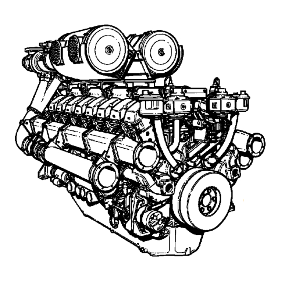
- Page 6 PHOTOGRAPHS 4012 TAG 4012 TAG 4012/16 Diesel, February 1997...
- Page 7 PHOTOGRAPHS 4016 TAG 4016 TAG 4012/16 Diesel, February 1997...
- Page 8 BRIEF DESCRIPTION OF THE 4012/16 SERIES DIESEL ENGINES 4012TWG 12 cylinder "V" form diesel engine, water cooled, turbocharged (twin turbochargers), jacket water cooled charge air coolers and oil coolers in engine cooling circuit. Earlier engines with vertical air cleaners, later engines with horizontal air cleaners.
- Page 9 GENERAL INFORMATION SAFETY Engine lift equipment Use only the lift equipment which is designed for the engine. Use lift equipment or obtain assistance to lift heavy engine components such as the cylinder block, cylinder head, flywheel housing, crankshaft and flywheel. Check the engine lift brackets for security before the engine is lifted.
- Page 10 GENERAL INFORMATION Environmental protection There legislation protect environment from the incorrect disposal of used lubricating oil. To ensure that the environment is protected, consult your Local Authority who can give advice. Viton seals Some seals used in engines and in components fitted to engines are made from Viton.
- Page 11 DIESEL ENGINE DATA ‘B’ BANK ‘A’ BANK Fig. B For full technical data please refer to the Product Information Manual. Type: Water-cooled, turbocharged, charge cooled, industrial diesel engine. RANGE 4012 4016 Cycle 4 stroke 4 stroke No. of cylinders Configuration V-form V-form Bore...
-
Page 12: Fuel System
DIESEL ENGINE DATA TYPICAL COOLING SYSTEM 4006 4008 Approved Coolants) page 21 Total water capacity Ltrs Gals Spec Ltrs Gals Spec 56.1 TAG1 TAG1 TAG2 TAG2 TWG* TWG2 TWG2* TEG** 23.7 TEG** Engine only Engine with heat exchanger Max radiator top tank temperature 93°C Max water temperature into engine 80°C... -
Page 13: Lubrication System
DIESEL ENGINE DATA LUBRICATION SYSTEM 4012 4016 Recommended oil pages 19 and 20 Type of system Wet sump, external engine mounted oil pump Total oil capacity (including cooler and filter) 178 litre (39.2 gal) 238 litre (53 gal) Sump capacity (dipstick) Min. -
Page 14: Electrical System
DIESEL ENGINE DATA TYPICAL DRY WEIGHT 4012 4016 Dry weight (engine) 4360 kg 4012TAG 5500 kg 4016TAG 4360 kg 4012TAG1 5750 kg 4016TAG1 4400 kg 4012TAG2 5750 kg 4016TAG2 4975 kg 4012TWG 5940 kg 4016TWG/2 5315 kg 4012TWG2 5820 kg 4016TEG 4680 kg 4012TEG2 Dry weight engine &... - Page 15 DIESEL ENGINE DATA PROTECTION EQUIPMENT Before resetting protection equipment, it must be established whether special settings (for that individual engine) have been specified in the engine sales contract. This is particularly important with ALL high water temperature settings, and ALL Cogen applications. Standard settings for protection equipment are as follows:- Alarm Shutdown...
- Page 16 TORQUE SETTINGS IT IS ESSENTIAL THAT THE CORRECT LENGTH OF SCREW OR WARNING BOLT IS USED. INSUFFICIENT LENGTH MAY RESULT IN THE THREAD BEING STRIPPED, WHEREAS TOO LONG A THREAD MAY RESULT IN BOTTOMING IN A BLIND HOLE, OR CATCHING ON ADJACENT COMPONENTS. NOTE: * Bolt heads and threads must be lubricated with clean engine oil.
- Page 17 TORQUE SETTINGS LUBRICATING OIL PUMP lbf.ft Bolts, pump housing to gearcase plate Thin nut, gear to drive shaft CAMSHAFT GROUP Camshaft gear bolt Camshaft thrust plate bolt Camshaft follower housing bolt Idler gear hub bolts WATER PUMP Water pump gear nut Water header to oil cooler bolts Water pump to gearcase bolts Raw water pump gear securing nut, dry thread...
- Page 18 TORQUE SETTINGS GENERAL TORQUE LOADINGS The following torque loadings are general for metric coarse threads and for grade 8.8 steel, but do not supersede the figures quoted above. THREAD lbf ft GENERAL NOTE: M10 - 12.9 Steel TIGHTENING TORQUES These are based on 85% of the proof loads designated in BS3692. 4012/4016 Diesel, February 1997...
- Page 19 LUBRICATING OIL RECOMMENDATIONS QUANTITY OF OIL Sump Capacity Dipstick 4012 4016 Minimum 136 litre(30 gal) 147 litre (33 gal) Maximum 159 litre (35 gal) 214 litre (47 gal) TYPE OF OIL The industrial diesel engine should be lubricated with a good quality oil conforming to API CD or CCMC D4 specifications.
- Page 20 The following list gives details of some of the oils that meet the required specifications. Note that the brand names may change as oils are upgraded or reformulated. An up-to-date list is maintained by Perkins Engines (Stafford) Limited of major oil companies products and information, which can be obtained from Perkins Engines (Stafford) Service Department.
- Page 21 The 50/50 mixture will give frost protection down to -35°C. In areas where Shell Safe Premium is not available contact Perkins Engines (Stafford) Limited for advice on a recommended alternative. 4012/16 Diesel, February 1997...
- Page 22 British Standard Specification 2869. Class A1 or A2. If fuels other than the above classes are considered, the operator must consult Perkins Engines (Stafford) Limited, and ensure that a suitable grade of lubricating oil is used.
- Page 23 OPERATING INSTRUCTIONS PREPARING FOR INITIAL START FILLING THE ENGINE WITH OIL NEVER OPERATE WARNING THE ENGINE WHEN THE OIL LEVEL IS BELOW THE MINIMUM MARK OR ABOVE THE MAXIMUM. ALWAYS WEAR PROTECTIVE GLOVES WHEN HANDLING ENGINE OIL. Fig. 1 Remove the drain plug to ensure that the sump is clean and empty.
- Page 24 OPERATING INSTRUCTIONS For earlier engines not fitted with a stop lever, disconnect the battery leads and remove the electric plug from the governor by unscrewing the locking collar and pulling the plug out of its socket. (See Fig. 2 & Fig. Operate the starting control or key switch and motor the engine over on the starter until an oil pressure of approximately 40 kPa (5 lb/...
- Page 25 OPERATING INSTRUCTIONS BATTERIES (SUPPLIED DRY CHARGED) See Installation Manual HAND PROTECTION WARNING MUST BE WORN WHEN CHECKING THE BATTERY ELECTROLYTE. NEVER CHECK WITH A NAKED FLAME. Check the level of electrolyte in each battery cell which should be approximately 8 mm above the plates.
- Page 26 OPERATING INSTRUCTIONS PRIMING AND VENTING THE FUEL SYSTEM AS FITTED ON THE EARLIER 12 & 16 CYLINDER ENGINES. Loosen the union nut on the fuel feed pipe from the fuel filter, Fig. 5. Operate the priming pump by pressing the rubber button Fig.
- Page 27 OPERATING INSTRUCTIONS PRIMING AND VENTING THE FUEL SYSTEM AS FITTED ON LATER 12 & 16 CYLINDER ENGINES Loosen the union nut on the fuel feed pipe to the front cylinder head on the fuel rail Fig. 9. NOTE: The fuel system should not be bled from the water trap/sedimenter filter (if fitted), since this is on the suction side of the lift pump.
- Page 28 OPERATING INSTRUCTIONS ALWAYS BE IN A WARNING POSITION TO MANUALLY STOP THE ENGINE IN THE EVENT OF A MALFUNCTION BY OPERATING THE EMERGENCY STOP BUTTON. INITIAL STARTING OF THE ENGINE WHEN FITTED WITH THE ELECTRONIC GOVERNOR Fig. 12 With the load disengaged, ensure that the stop control on engine/panel is in the 'stop' position, and that the air shut-off valves have been manually set to the 'run' position (see...
- Page 29 OPERATING INSTRUCTIONS INITIAL STARTING OF THE ENGINE WHEN FITTED WITH THE REGULATEURS EUROPA 2100 HYDRAULIC GOVERNOR NOTE: It is recommended that for initial starting of new or overhauled engines, any automatic starting or control systems are by- passed and the engine is controlled manually with the load disengaged, but with Fig.
- Page 30 OPERATING INSTRUCTIONS NORMAL STARTING PROCEDURE WHEN FITTED WITH THE REGULATEURS EUROPA 2100 GOVERNOR AND A WOODWARD TYPE UG10 OR 3161 Ensure that where possible the load is off. Set the engine switch to the 'run' position and press the starter button, the engine should start immediately and run up to full speed.
- Page 31 OPERATING INSTRUCTIONS ENGINE SHUTDOWN The engine is normally stopped by operating an electric stop control via a key switch. In this case it is only necessary to turn the key in an anti-clockwise direction which de- energises the stop solenoids to stop the engine.
- Page 32 LIGHT LOAD OPERATION & STANDBY GENERATING SETS If an engine is operated on a load less than 25-30% of its rated output, certain symptoms will be observed which may give cause for concern. The usual results of this operation are heavier than normal...
- Page 33 INSTRUMENT PANEL (ENGINE MOUNTED) DESCRIPTION The instrument panel is flexibly mounted on the engine (see Fig. 15). The basic engine mounted panel includes the instruments associated with the engine only, which show the readings for the following conditions: Cooling water temperature 4 Battery charging rate Fuse holder Lubricating oil temperature 5...
- Page 34 INSTRUMENT PANEL Engine water temperature gauge (Fahrenheit/Centigrade) Fig. 16 The coolant temperature during normal operation should be between 65°C - 85°C (149°F - 185°F). If the temperature should rise above 93°C (200°F) for a prolonged period of time, stop the engine and investigate the cause.
- Page 35 INSTRUMENT PANEL Engine tachometer and hour counter (revolutions per minute x 1000 and hours) Fig. 20 The electrically operated tachometer/ hour counter shows the speed of the engine in r/min. and the actual operating hours engine run. tachometer/hour counter starts operating from an alternator voltage of 12 V onwards, which has already been Fig.
- Page 36 EXHAUST TEMPERATURE GAUGE (OPTIONAL) DESCRIPTION (Fig. 22) All exhaust temperature gauges are of the high accuracy type with digital LCD display, Red terminal and are powered by the engine 24 volt Compensating cables system. Red terminal A two-point gauge may be fitted to these Locknuts engines, measuring...
- Page 37 EXHAUST TEMPERATURE GAUGE (OPTIONAL) SPECIFICATION Temperature range -20/+800°C Resolution 1°C Accuracy + 0.5% F.S.D. Probe fitting 3/8" BSP Terminal size to suit 4BA eyelet connector Cable size 2 core 7 strand 0.1 mm dia. Type of cable Compensating type K i.e.
- Page 38 EXHAUST TEMPERATURE GAUGE (OPTIONAL) A four point gauge may also be fitted which measures the exhaust temperature of both banks before well after turbocharger (see Fig. 25 and Fig. 26). NOTE: These gauges are wired with 'A' bank defined as 'the left hand bank as viewed from the FRONT (free end) of the engine'.
- Page 39 MAINTENANCE SCHEDULE & CHECKLISTS Towards the rear of this section are two check sheets, one for continuous duty sets and one for standby duty sets, which are to be used as a guide for operators and maintenance personnel. following schedule details some of the maintenance to be carried out as in the maintenance check lists.
- Page 40 MAINTENANCE SCHEDULE & CHECKLISTS AIR FILTER MAINTENANCE GENERAL SERVICING INSTRUCTIONS Servicing procedures include replacing the filter element, cleaning the filter housing, and assuring that piping hose connections from the filter outlet to the turbocharger intake are sealed and airtight. (See Fig. 27). REPLACE ANY WARNING Fig.
- Page 41 MAINTENANCE SCHEDULE & CHECKLISTS DAILY INSPECTION DISCONNECT WARNING BATTERIES OR ANY OTHER MEANS OF STARTING. ALWAYS WEAR PROTECTIVE GLOVES. DRAINING THE WATER TRAP/ SEDIMENTER (WHERE FITTED) There are no moving parts or elements to service, however daily open the drain plug to remove collected water and sediment.
- Page 42 MAINTENANCE SCHEDULE & CHECKLISTS EVERY 250 HOURS OR 6 MONTHS CENTRIFUGAL OIL FILTER (IF FITTED) DISCONNECT WARNING BATTERIES OR ANY OTHER MEANS OF STARTING. ALWAYS WEAR PROTECTIVE GLOVES. Stop the engine, and allow time for the oil to drain back to the sump. Refer to Fig. 30. Slacken safety clamp (1) unscrew cover nut and lift off cover.
- Page 43 MAINTENANCE SCHEDULE & CHECKLISTS EVERY 250 HOURS OR EVERY 6 MONTHS ALTERNATOR DRIVE BELT DISCONNECT WARNING BATTERIES OR ANY OTHER MEANS OF STARTING THE ENGINE. Remove the small mesh guard around the Fig. 31 alternator. The toothed belt used to drive the alternator relies on tooth engagement to FAN BELTS transmit load.
- Page 44 MAINTENANCE SCHEDULE & CHECKLISTS EVERY 250 HOURS OR EVERY 6 MONTHS BEARINGS AND BELTS (COVRAD RADIATOR) DISCONNECT WARNING BATTERIES OR ANY OTHER MEANS OF STARTING THE ENGINE. Remove the mesh guard around the fan belts, grease the fan bearings (2) and jockey pulley bearings (4) Fig.
- Page 45 MAINTENANCE SCHEDULE & CHECKLISTS EVERY 250 HOURS OR EVERY 6 MONTHS CRANKCASE BREATHER, EARLIER ENGINES (RADIATOR COOLED) DISCONNECT WARNING BATTERIES OR ANY OTHER MEANS OF STARTING. ALWAYS WEAR EYE PROTECTION AND PROTECTIVE GLOVES WHEN CLEANING BREATHER. An extension pipe runs from both sides of the engine gearcase to the engine breathers, which are mounted on each side of the radiator Fig.
- Page 46 MAINTENANCE SCHEDULE & CHECKLISTS EVERY 250 HOURS OR EVERY 6 MONTHS CRANKCASE BREATHER (HEAT EXCHANGER COOLED ENGINES) The crankcase breathers are mounted on the side of each thermostat housing and are connected to the engine via an extension pipe and bend fitted on each side of the gearcase (see Fig.
- Page 47 MAINTENANCE SCHEDULE & CHECKLISTS EARLY 250 HOURS OR 6 MONTHS CRANKCASE BREATHER (RADIATOR OR HEAT LATEST EXCHANGER COOLED ENGINES) The crankcase breathers are mounted on the side of the thermostat housings and are connected to the engine via an extension pipe and bend fitted on each side of the gearcase (see Fig.
- Page 48 MAINTENANCE SCHEDULE & CHECKLISTS EVERY 250 HOURS OR EVERY 6 MONTHS CLOSED CIRCUIT BREATHER SYSTEM (IF FITTED) The closed circuit separators are mounted just behind the thermostat housing via an expansion pipe and hose bend which is fitted on each side of the gearcase and is connected to the air inlet via the breather valve see Fig.
- Page 49 MAINTENANCE SCHEDULE & CHECKLISTS EVERY 250 HOURS OR EVERY 6 MONTHS Two breather valves are mounted in the circuit. To remove release the pipe clips and pull away from the valve manifold. Wash the breather thoroughly (with suitable detergent) paying particular attention to any deposits on the internal area of the breather.
- Page 50 MAINTENANCE SCHEDULE & CHECKLISTS EVERY 250 HOURS OR EVERY 6 MONTHS CHANGING ENGINE OIL AND OIL FILTERS (STANDARD HORIZONTAL TYPE) DISCONNECT WARNING BATTERIES OR ANY OTHER MEANS OF STARTING. WEAR PROTECTIVE GLOVES. With the engine stopped, place a suitable Fig. 43 container of at least 214 litres (47 gal) beneath the drain plug (which is situated on the bottom edge of the sump directly under...
- Page 51 MAINTENANCE SCHEDULE & CHECKLISTS EVERY 250 HOURS OR 6 MONTHS CHANGING THE FILTER ELEMENTS WHEN THE ENGINE IS STOPPED All that is necessary is to unscrew the canisters with a strap wrench as shown in Fig. 44, without moving the change-over valve, as there is no pressure in the system when the engine is stationary.
- Page 52 MAINTENANCE SCHEDULE & CHECKLISTS EVERY 250 HOURS OR 6 MONTHS NOTE: Prepare for some spillage of oil as each canister is removed, by placing a bowl CHANGING THE CHANGE OVER FILTER of about 5 litres or 1 gallon capacity under ELEMENTS WITHOUT STOPPING THE the filters.
- Page 53 MAINTENANCE SCHEDULE & CHECKLISTS EVERY 250 HOURS OR EVERY 6 MONTHS CHANGING FUEL FILTER ELEMENTS NOTE: Ensure complete cleanliness is adhered to. DISCONNECT WARNING BATTERIES OR OTHER MEANS OF STARTING. ALWAYS WEAR PROTECTIVE GLOVES Fig. 46 HORIZONTAL FUEL FILTER (EARLY ENGINES) First turn off the fuel on installations having an overhead supply, drain the sediment trap or...
- Page 54 MAINTENANCE SCHEDULE & CHECKLISTS EVERY 250 HOURS OR EVERY 6 MONTHS CHANGING THE CHANGE OVER FUEL FILTER ELEMENTS WHEN THE ENGINE IS STOPPED All that is necessary is to unscrew the canisters with a strap wrench as shown in Fig. 48, leaving the change-over lever in the vertical position as there is no pressure in the fuel system with the engine stationary.
- Page 55 MAINTENANCE SCHEDULE & CHECKLISTS EVERY 250 HOURS OR 6 MONTHS EQUALISE ROCKER BRIDGES AND SETTING VALVE CLEARANCES NOTE: The bridge pieces must be set before attempting to set the valve clearances. DISCONNECT WARNING BATTERIES AND OTHER MEANS OF STARTING THE ENGINE.
- Page 56 MAINTENANCE SCHEDULE & CHECKLISTS Set Bridge Pieces Engine 4012 Valves Rocking on and Valve Clearances T.D.C. Cylinder No. on Cylinder no. A1 & A6 B1 & B6 A2 & A5 B2 & B5 A3 & A4 B3 & B4 A1 & A6 B1 &...
- Page 57 MAINTENANCE SCHEDULE & CHECKLISTS EVERY 250 HOURS OR EVERY 6 MONTHS If the valves required to be rocking are closed, rotate the engine one revolution, which will bring these valves to the rocking position. The flywheel housing has an inspection hole directly below the 'B' bank turbocharger(s) through which the flywheel markings may be seen to line up with the pointer set in the...
- Page 58 MAINTENANCE SCHEDULE & CHECKLISTS EVERY 250 HOURS OR EVERY 6 MONTHS FAILURE TO WARNING EQUALISE A BRIDGE PIECE MAY RESULT IN ENGINE DAMAGE. ALWAYS CHECK THAT THE PARTS FIT TOGETHER AND MOVE FREELY, BEFORE ASSEMBLY. Fig. 52 E.g. to adjust valves and bridge pieces on No.
- Page 59 MAINTENANCE SCHEDULE & CHECKLISTS OVERHAUL PERIODS CYLINDER HEAD NOTE: Service exchange cylinder heads The intervals at which routine overhauls are are available. required, to keep an engine in good operating condition, will vary considerably Remove the cylinder heads from the engine depending upon operating conditions, the and remove the inlet and exhaust valves.
- Page 60 The oil change intervals may be altered according to operating experience over 1000 GENERAL ATTENTION hours by agreement with Perkins Engines Also carry out all checks and fit replacement (Stafford) Limited and subject to oil analyses parts as listed for each service period in the being carried out on a regular basis, see Maintenance Schedule.
- Page 61 PREVENTIVE MAINTENANCE SCHEDULE FOR ENGINES IN STAND-BY DUTY For engines which are in use for a total of less than 400 hours in every twelve months, the schedule below must be used: The preventive maintenance operations must be applied at the interval (hours or months) which occurs first.
- Page 62 PREVENTIVE MAINTENANCE SCHEDULE FOR ENGINES IN CONTINUOUS DUTY For preventive maintenance operations must be applied at the interval (hours or months) which occurs first. Daily Every 250 hours or 6 months Every 2500 hours or 12 months Operation Check the coolant level ●...
- Page 63 4012/4016 ENGINE FAULT TRACING Fig. 54 4012/16 Diesel, February 1997...
- Page 64 4012 STARTING CIRCUIT, SINGLE STARTER WITH REPEATER RELAY (EARLY ENGINES) Starting circuit for 4012 engine range, read in conjunction with wiring diagram Fig. (Fig. 55) Terminal box Starter Repeater relay Emergency stop Starter motor Start relay Start inhibit relays Fuel stop solenoids (energised to run) Wire sizes 10 Magnetic pick-ups 11 Engine flywheel...
- Page 65 4012/16 STARTING CIRCUIT, STARTERS AND TWIN START RELAYS (EARLY ENGINES) Starting circuit for 4012 engine range, read in conjunction with wiring diagram Fig. (Fig. 56) Terminal box Starter motor 1 Starter motor 2 24 v Starting batteries Emergency stop switch Start relays Start inhibit relays Fuel stop solenoids (energised to run)
- Page 66 23 Two switch speed unit 24 Switch 2 overspeed Key (Fig. 57) 25 Switch 1 speed 600 rpm Wiring by Perkins 26 Micro switches Start batteries 27 Engine fault switches left/right/banks Repeater relay 28A Water temp. right Engine instrument panel 28B Water temp.
- Page 67 22A Oil pressure left 22B Oil pressure right Key (Fig. 58) 23 Fuel stop solenoids (energised to run) Terminal box Perkins supply 24 Two switch speed unit Starter motor 1 25 Switch 2 overspeed Starter motor 2...
- Page 68 4012/16 WIRING DIAGRAM, SINGLE STARTER AND HYDRAULIC GOVERNOR (EARLY ENGINES) Engine fitted with regulators Europa 18 Solenoid hydraulic governor 19 Engine fault switches left/right bank 20A Water temperature NOTE: All switches shown engine at rest 20B Water temperature 21A Oil pressure (Fig.
- Page 69 4012/16 WIRING DIAGRAM, TWIN STARTERS, SINGLE START RELAY, ORIGINAL AIR SHUT OFF VALVES 21 Switch 2 overspeed (Fig. 60) 22 Switch 1 speed 700 rpm Terminal box 23 Micro switches Starter motor 1 24 Engine fault switches left/right bank Starter motor 2 25A Water temperature switch Engine instrument panel 25B Water temperature switch...
- Page 70 4012/16 WIRING DIAGRAM, TWIN STARTERS, SINGLE START RELAY, ELECTRONIC GOVERNOR (LATER ENGINES) Engine engine wiring to engine fitted terminal box on diesel engines. (Fig. 61) Engine fitted terminal box Starter motor 1 Starter motor 2 Emergency stop Start inhibit relays Start relay Fuel stop solenoids (energised to run) Magnetic pick-ups...
- Page 71 4012/16 WIRING DIAGRAM, TWIN STARTERS, ELECTRONIC GOVERNOR (INTERMEDIATE ENGINES) 19 Magnetic pick-ups (Fig. 62) 20 Engine flywheel Engine fitted terminal box 21 Electronic governor control box Two off air shutoff solenoid valves 22 Electronic governor actuator energise to stop. To operate only in 23 NOTE: All switches are shown with the conjunction with overspeed fault.
- Page 72 4016 WIRING DIAGRAM, TWIN STARTERS, ELECTRONIC GOVERNOR (INTERMEDIATE ENGINES) 19 Magnetic pick-ups (Fig. 63) 20 Engine flywheel Engine fitted terminal box 21 Electronic governor control box Four off air shutoff solenoid valves 22 Electronic governor actuator energised to stop. To operate only in 23 NOTE: All switches are shown with the conjunction with overspeed fault.
- Page 73 4012 WIRING DIAGRAM TWIN STARTERS AND ELECTRONIC GOVERNOR (CURRENT ENGINES) 18 Magnetic pick-ups (Fig. 64) 19 Engine flywheel Engine fitted terminal box 20 Electronic governor control box Oil pressure switch 21 Electronic governor actuator Starter motor 1 22 NOTE: All switches are shown with the Starter motor 2 engine at rest Battery charging alternator...
- Page 74 4016 WIRING DIAGRAM, TWIN STARTERS, ELECTRONIC GOVERNOR (CURRENT ENGINES) 20A Water temperature (Fig. 65) 20B Water temperature Engine fitted terminal box 21A Oil pressure Oil pressure switch 21B Oil pressure Starter motor 1 22 All switches shown engine at rest Starter motor 2 23 Typical linking box to controller Battery charging alternator...
-
Page 75: California Proposition 65 Warning
Diesel engine exhaust and some of its constituents are known to the State of California to cause cancer, birth defects, and other reproductive harm. Battery posts, terminals and related accessories contain lead and lead compounds. Wash hands after handling. © 1998 Perkins Engines Company Limited All Rights Reserved...
Need help?
Do you have a question about the 400 Series and is the answer not in the manual?
Questions and answers