
Related Manuals for Perkins 4016-61TRS1


Summary of Contents for Perkins 4016-61TRS1
- Page 1 SEBU8430-02 (en-us) June 2022 Operation and Maintenance Manual 4016-61TRS1 and 4016-61TRS2 Gas Engines...
- Page 2 If a tool, procedure, work method or operating technique that is not specifically recommended by Perkins is used, you must satisfy yourself that it is safe for you and for others. You should also ensure that you are authorized to perform this work, and that the product will not be damaged or become unsafe by the operation, lubrication, maintenance or repair procedures that you intend to use.
-
Page 3: Table Of Contents
SEBU8430-02 Table of Contents Table of Contents Refill Capacities..........37 Maintenance Interval Schedule (Engines Foreword ............4 Powered by Natural Gas Only)...... 50 Safety Section Reference Information Section Safety Messages..........6 Reference Materials ........78 Additional Messages ........12 Index Section General Hazard Information...... -
Page 4: Foreword
State of arises regarding your engine, or this manual, please California to cause cancer, birth defects, consult with your Perkins dealer or your Perkins distributor for the latest available information. and other reproductive harm. WARNING – This product can... - Page 5 Perkins distributor offers various options regarding overhaul programs. If you experience a major engine failure, there are also numerous after failure overhaul options available. Consult with your Perkins dealer or your Perkins distributor for information regarding these options.
-
Page 6: Safety Section
If a warning sign is attached to a part of the engine that is replaced, install a new warning sign on the replacement part. Your Perkins dealer or your distributor can provide new warning signs. The safety messages that may be attached on the... - Page 7 SEBU8430-02 Safety Section Safety Messages Warning Labels Position Bank A Illustration 1 g07083386 Typical example (1) Universal warning (3) No step warning (5) Hot fluid under pressure warning (2) Ether warning (4) Hot surface warning...
- Page 8 SEBU8430-02 Safety Section Safety Messages Warning Labels Position Bank B Illustration 2 g07083440 Typical example (1) Universal warning (3) Ether warning (5) Hot surface warning (2) No step warning (4) Hot fluid under pressure warning (6) Rotating shaft hand crush hazard...
- Page 9 SEBU8430-02 Safety Section Safety Messages Universal Warning The ether warning labels are installed on both banks of the engine underneath the engine air cleaner. Do Not Step Illustration 3 g06019365 Universal Warning label Illustration 5 g01393287 Do not operate or work on this equipment unless you have read and understand the instructions and warnings in the Operation and Maintenance Do not use this surface as a step or platform.
- Page 10 SEBU8430-02 Safety Section Safety Messages The hot surface warning labels are on the oil coolers The hot fluids under pressure labels are on the oil that are on both banks of the engine. coolers that are on both banks of the engine. Rotating Shaft Hand Crush Hazard Hot Fluid Under Pressure Illustration 7...
- Page 11 SEBU8430-02 Safety Section Safety Messages The rotating shaft hand crush hazard label (6) is on the cover of the crankshaft vibration damper guard. Engine Oil Level Illustration 9 g01241033 Typical example On earlier engines, the warning label for checking the engine oil level is located on the inlet manifold on the left side of the engine.
-
Page 12: Additional Messages
SEBU8430-02 Safety Section Additional Messages The warning label for derating engine information is i09119848 supplied loose. The warning label for derating engine General Hazard Information information is located on the control box. Refer to Original Equipment Manufacturer (OEM) information for the location of the control box. i07199910 Additional Messages Illustration 12... - Page 13 SEBU8430-02 Safety Section General Hazard Information • The engine is stopped. Ensure that the engine cannot be started. • The protective locks or the controls are in the applied position. • Disconnect the batteries when maintenance is performed or when the electrical system is serviced.
- Page 14 Hexavalent Chromium Perkins equipment and replacement parts comply with applicable regulations and requirements where originally sold. Perkins recommends the use of only genuine Perkins replacement parts. Hexavalent chromium has occasionally been detected on exhaust and heat shield systems on Perkins engines.
-
Page 15: Burn Prevention
Asbestos Information Perkins equipment and replacement parts that are shipped from Perkins engine company limited are asbestos free. Perkins recommends the use of only genuine Perkins replacement parts. Use the following guidelines when you handle any replacement parts Illustration 16... -
Page 16: Fire Prevention And Explosion Prevention
15 to 60 minutes and obtain immediate medical attention. If the application involves the presence of combustible gases, consult your Perkins dealer for Batteries additional information about suitable protection devices. All local regulations must be observed. - Page 17 Tighten all connections to the recommended torque. Leaks can cause fires. Repair any lines that are loose or damaged. Leaks can cause fires. Consult your Perkins dealer for Oil filters and fuel filters must be properly installed. repair or for replacement parts.
-
Page 18: Crushing Prevention And Cutting Prevention
SEBU8430-02 Safety Section Crushing Prevention and Cutting Prevention Make sure that all clamps, guards, and heat shields Do not carry tools or supplies when you mount the are installed correctly. During engine operation, this engine or when you dismount the engine. Use a hand will help to prevent vibration, rubbing against other line to raise and lower tools or supplies. -
Page 19: Engine Starting
SEBU8430-02 Safety Section Engine Starting i03101447 i02436641 Engine Starting Electrical System If a warning tag is attached to the engine start switch Never disconnect any charging unit circuit or battery or to the controls, DO NOT start the engine or move circuit cable from the battery when the charging unit the controls. - Page 20 SEBU8430-02 Safety Section Electrical System Uncontrolled electrical circuit paths can result in damage to the crankshaft bearing journal surfaces and to aluminum components. The connections for the grounds should be tight and free of corrosion. The engine alternator must be grounded to the negative “-”...
-
Page 21: Product Information Section
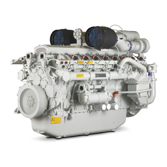
SEBU8430-02 Product Information Section Model Views and Specifications Product Information Section Model Views and Specifications i02885828 Model View Illustrations The illustrations show various typical features of 4016 Series TRS Engine. The illustrations do not show all of the options that are available. Illustration 20 g01525185 Typical example... - Page 22 This mixture is compressed by the turbocharger. The mixture passes through the tumbulator, and the charge coolers, and into the inlet manifolds. The The Perkins Engines were developed in order to speed and the load is governed by electronically provide gas engines for generator set applications.
- Page 23 SEBU8430-02 Product Information Section Specifications • Voltage The system is used when recovery of heat is not an important factor. • Duration of the spark Cogeneration engine • Ignition timing Cogeneration uses energy from heat which would • Level of energy of the ignition otherwise be wasted.
- Page 24 SEBU8430-02 Product Information Section Specifications Table 1 4016 Engine Specifications Rated rpm 1500 Number of Cylinders Configuration Vee-form Bore 160 mm (6.299 inch) Stroke 190 mm (7.480 inch) Displacement 61.123 L (3729.954 in Compression ratio 13:1 Aspiration Turbocharged Rotation (flywheel end) Counterclockwise Inlet valve lash (cold) 0.40 mm (0.016 inch)
-
Page 25: Product Identification Information
SEBU8430-02 Product Information Section Product Identification Information Product Identification Perkins dealers and Perkins distributors require all of these numbers in order to determine the components Information that were included in the engine. This permits accurate identification of replacement part numbers. - Page 26 SEBU8430-02 Product Information Section Plate Locations and Film Locations Illustration 24 g01229580 The location of the serial number plate for vee-form engines The serial number plate (1) on a vee-form engine is located on the rear face of the cylinder block (bank A).
-
Page 27: Operation Section
If alterations are made, ensure that correct lifting devices are provided. Consult your Product Lifting Perkins dealer or your Perkins distributor for information regarding fixtures for correct engine lifting. NOTICE i03139740... -
Page 28: Gauges And Indicators
Determine and correct the cause of any significant change in the readings. Consult your Perkins dealer or your Perkins distributor for assistance. NOTICE If no oil pressure is indicated, STOP the engine. If maximum coolant temperature is exceeded, STOP the engine. -
Page 29: Features And Controls
Air/Fuel Ratio the derate to determine the maximum temperatures into the engine and the altitude derate. Contact your The correct air/fuel ratio is very important for the Perkins distributor or Perkins dealer for more information. following considerations: • Margin of detonation i02894958 •... - Page 30 SEBU8430-02 Operation Section Alarms and Shutoffs • Protection from detonation The detonation system operates by measuring vibrations on the crankcase. The signal is processed in order to eliminate normal engine vibrations. If Switches detonation above a predetermined level is detected the ignition timing is retarded.
- Page 31 SEBU8430-02 Operation Section Control Panel • Conditions which cause each control to function • Resetting procedure that is required before starting the engine Testing Alarms and Shutoffs Alarms must function properly in order to provide timely warning to the operator. Shutoffs help to prevent damage to the engine.
-
Page 32: Engine Starting
SEBU8430-02 Operation Section Engine Starting Engine Starting • Check the coolant level. Observe the coolant level in the header tank (if equipped). Maintain the coolant level to the “FULL” mark on the header i09210539 tank. Before Starting Engine • Observe the air cleaner service indicator. Service the air cleaner when the diaphragm enters the red zone, or when the red piston locks in the visible position. - Page 33 SEBU8430-02 Operation Section Starting the Engine 1. Remove the spark plugs from four of the engines Perform the procedures that are described in this Operation and Maintenance Manual, “Before Starting cylinders, refer to Disassembly and Assembly, Engine” (Operation Section). “Spark Plugs - Remove and Install” 2.
- Page 34 SEBU8430-02 Operation Section Starting with Jump Start Cables 4. Enable the ignition system. 8. The engine is now operating. 5. Turn the manual gas shutoff valve to the OPEN Operation of the Generator Set position. Control Panel 6. Start the engine. Refer to the engine starting procedure and refer to OEM in order to start the For information on operation for a specific generator set control panel, refer to the Operation and...
-
Page 35: Engine Operation
SEBU8430-02 Operation Section Engine Operation Engine Operation i02894963 Engine Operation Proper operation and maintenance are key factors in attaining the maximum service life and economy for the engine. Follow the instructions in this Operation and Maintenance Manual and Systems Operation, Testing and Adjusting in order to minimize operating costs and maximize the service life of the engine. -
Page 36: Engine Stopping
SEBU8430-02 Operation Section Engine Stopping Engine Stopping NOTICE Stopping the engine immediately after the engine has been operating under a load can result in overheating i02978181 and accelerated wear of the engine components. Emergency Stopping Allow the engine to gradually cool before stopping the engine. -
Page 37: Maintenance Section
SEBU8430-02 Maintenance Section Refill Capacities Maintenance Section Water Water is used in the cooling system to transfer heat. Refill Capacities Distilled water or deionized water is recommended for use in engine cooling systems. DO NOT use the following types of water in cooling i08462011 systems: Hard water, softened water that has been Fluid Recommendations... - Page 38 • Freezing • SCA Supplement Coolant Additive, • Cavitation of the water pump concentrated inorganic inhibitor package For optimum performance, Perkins recommends a • ASTM American Society for Testing and 50 percent by volume of glycol in the finished coolant Materials (also referred to as 1:1 mixture).
- Page 39 Correct additions to the Extended Life level of corrosion, boiling, and freezing protection as Coolant ELC or ELI. Perkins recommends a 6 percent to 8 percent concentration of SCA in those cooling systems. Distilled water or deionized water is NOTICE preferred.
- Page 40 To change from heavy-duty antifreeze to the Perkins 8. Repeat Steps 6 and 7 until the system is ELC, perform the following steps: completely clean. 9. Fill the cooling system with the Perkins Premixed NOTICE Care must be taken to ensure that all fluids are con- ELC.
- Page 41 Perkins Extended Life Inhibitor (ELI) is water-based coolant that does not contain glycol. Perkins ELI is for applications that do not require freeze protection. Exceptions are listed here. Failure to follow these recommendations can or will result in failures.
- Page 42 ELI into a clean container and mix thoroughly by Mixing Perkins ELI and Perkins ELC manual stirring or mechanical agitation. Since Perkins ELI and Perkins ELC are based on the If the preferred method cannot be performed, a same corrosion inhibitor technology, Perkins ELI can Perkins ELI mixture can be made by adding Perkins be mixed with Perkins ELC.
- Page 43 The size of the cooling system determines the amount of SCA that is needed. If using non Perkins coolants, refer to the coolant Use the equation that is in Table 12 to determine the manufacturer for information on a compatible SCA.
- Page 44 Some commercial cooling system cleaners can be Standard type and Quick Flush type, both types can acceptable quality water. Run the engine for 20 be used in all Perkins engine cooling systems. minutes and then drain the water. Consult your Perkins distributor for further guidance.
- Page 45 SCA that is required for maintenance, In engine cooling systems that use water alone, if necessary. Perkins recommends the use of SCA. SCA helps to prevent the following conditions from occurring: Note: Specific engine applications may require maintenance practices to be periodically evaluated to •...
- Page 46 Minimum TBN and maximum TAN will need to be agreed with the oil supplier prior to testing. It is important to work with an oil supplier or Perkins distributor to select the most appropriate oil based on your application.
- Page 47 • Mine gas • Lower calorific value The gas specification requirements are to be used as a guide only. Perkins require a full gas analysis to be • Methane number supplied at the inquiry stage of an engine order. Engine rating depends on the low calorific value of •...
- Page 48 10° to 50°C (50° to 122°F) The gas specification requirements are to be used as • Methane number a guide only. Perkins require a full gas analysis to be supplied at the inquiry stage of an engine order. i02885763 Engine rating depends on the methane number and...
- Page 49 SEBU8430-02 Maintenance Section Refill Capacities 4016-61TRS Table 16 4016-61 TRS Refill Capacities Compartment or System Quarts Liters Crankcase Oil Sump Total Lubrication System Cooling System To maintain the cooling system, the Total Cooling System capacity must be known. The approximate capacity is for the engine cooling system.
-
Page 50: Maintenance Interval Schedule (Engines Powered By Natural Gas Only)
For other gases, “ Fan Drive Pulley - Check“ ....69 consult Perkins Applications Engineering (Stafford) for more information. - Page 51 SEBU8430-02 Maintenance Section Engines Powered by Natural Gas Only “ Ignition System Spark Plugs - Inspect/ Replace“ ........70 Every Year “...
- Page 52 OEM for the appropriate the procedure. information. 2. Turn the aftercooler core on one side in order to Perkins recommends a scheduled inspection of the remove debris. Remove the debris that is alternator. Inspect the alternator for loose accessible.
- Page 53 SEBU8430-02 Maintenance Section Battery - Replace Note: Always recycle a battery. Never discard a battery. Dispose of used batteries to an appropriate recycling facility. 5. Remove the used battery. 6. Ensure that all the battery connections are clean and free from corrosion. 7.
- Page 54 SEBU8430-02 Maintenance Section Belts - Inspect/Adjust/Replace Thoroughly rinse the battery case with clean water. i03104600 Belts - Inspect/Adjust/Replace (Fan Drive Belts) The OEM supplies this system. Refer to the OEM for the appropriate information. i07134150 Belts - Inspect/Adjust/Replace Illustration 30 g01239310 (Alternator Belt) 4.
- Page 55 SEBU8430-02 Maintenance Section Carburetor Air/Fuel Ratio - Check/Adjust Refer to the Systems Operation, Testing and Adjusting for the correct procedure. i02450196 Control Panel - Inspect Inspect the condition of the panel. If a component is damaged, ensure that the component is repaired or that the component is replaced.
- Page 56 If necessary, add more coolant. Refer to Operation Note: The cooling system must be filled slowly. Refer and Maintenance Manual, “Cooling System to Perkins engines Stafford for more information. Coolant Level - Check”. 1. Close the drain cock on the charge water circuit 6.
- Page 57 Note: The cooling system must be filled slowly. Refer Typical example to Perkins Engines Stafford for more information. 3. Allow the system to drain. 1. Close the drain cock or install the drain plug on the radiator or the heat exchanger. Close the drain Charge Water System Fill cock on the engine oil cooler (1).
- Page 58 Refer to the Operation and Maintenance Manual, “Fluid recommendations”. Perkins POWERPART antifreeze with a concentration of 50% will give protection against frost to a temperature of −35 °C (−31 °F). The solution will also protect against corrosion.
- Page 59 If the temperature begins to rise, reduce the interval for inspecting the damper. If the temperature of the damper reaches 100 °C (212 °F), consult your Perkins dealer. Inspect the damper for evidence of dents, cracks, and leaks of the fluid.
- Page 60 Photographic documentation or video documentation is also • Damaged parts recommended. Consult your Perkins dealer for information on available borescopes. Perform any maintenance that is recommended by the OEM of the driven equipment. Refer to the...
- Page 61 SEBU8430-02 Maintenance Section Engine Air Cleaner Element - Replace • Maximum heat transfer characteristics 1. Remove the retaining clips (3). Remove the cover (4). • Ease of maintenance 2. Remove the old element (2). Dispose of the old element. i02947520 Engine Air Cleaner Element - Note: Ensure that dirt can not enter the air filter assembly.
- Page 62 SEBU8430-02 Maintenance Section Engine Crankcase Breather - Clean/Replace Illustration 40 g01223729 Illustration 41 g01224945 Typical service indicator Typical example In order to reset the indicator, you must press the 3. Remove the filter elements (3) from the breather button (1). body (4).
- Page 63 SEBU8430-02 Maintenance Section Engine Mounts - Check 3. Install the new filter element. Align the clips (1). Install the bowl (2). Connect the power supply to the engine. Operate the engine and check for leaks. i03032640 Engine Mounts - Check Misalignment of the engine and the driven equipment will cause extensive damage.
- Page 64 SEBU8430-02 Maintenance Section Engine Oil Filter (Auxiliary) - Change 2. Replace the sealing washer, if necessary. Install 4. Remove the filler cap (1). Fill the engine with the the drain plug. Tighten the plug to 68 N·m required amount of engine oil. Refer to Operation (50 lb ft).
- Page 65 Refer to Operation and Maintenance Manual, “Refill Capacities” for more NOTICE information. Perkins oil filters are manufactured to Perkins Engine Company LTD specifications. Use of an oil filter that NOTICE is not recommended by Perkins Engine Company If equipped with an auxilliary oil filter system or a re- LTD could result in severe damage to the engine.
- Page 66 SEBU8430-02 Maintenance Section Engine Oil Level - Check 3. Start the engine and run the engine for two NOTICE minutes. Perform this procedure in order to ensure If you operate the engine with the oil level above the that the lubrication system has oil and that the oil “MAX”...
- Page 67 • Iron - Fe less than 20 ppm Engine Speed/Timing Sensor - • Copper - Cu less than 40 ppm Clean/Inspect Note: Perkins Engines Stafford must agree to the maintenance schedule. Ensure that all power is disconnected to the engine before performing these procedures.
- Page 68 NOTICE Only qualified service personel should perform this maintenance. Refer to the Service Manual or your au- thorized Perkins dealer or your Perkins distributor for the complete valve lash adjustment procedure. Operation of Perkins engines with incorrect valve lash can reduce engine efficiency, and also reduce engine component life.
- Page 69 (66 lb ft). • Leaks 4. Install the guards (not shown). 5. Restore the electrical supply to the engine. • Loose connections Consult your Perkins dealer for assistance. i02478666 Fuel Filtration System - i02887782 Service Fan Drive Pulley - Check Engines that use bio-gas may require special 1.
- Page 70 SEBU8430-02 Maintenance Section Hoses and Clamps - Inspect/Replace • For the service of the fuel filter on the high • Anticipated expansion and contraction of the pressure gas fuel system, refer to the OEM for fittings information. Replace the Hoses and the Clamps i02430593 Hoses and Clamps - Inspect/ Replace...
- Page 71 SEBU8430-02 Maintenance Section Ignition System Timing - Check/Adjust Inspect the Spark Plug On the initial start-up of a new engine or an engine that has been serviced, it is possible for condensation to have built up in the spark plugs. If Inspect the spark plug closely for damage.
- Page 72 SEBU8430-02 Maintenance Section Inlet Air System - Inspect 2. Operate the engine and check the timing marks on i03140143 the flywheel. Jacket Water Heater - Check 3. If necessary, adjust the ignition timing. Remove the cap (not shown) that covers the screw for timing adjustment (1).
- Page 73 Overhaul (Major) If you elect to perform an overhaul without the services of a Perkins dealer, be aware of the following recommendations. Scheduling a Major Overhaul Replacing of Components Generally, a major overhaul is performed at 64000 hours.
- Page 74 • Valve train that includes the rocker gear values can be used to schedule a top end overhaul. i09157681 Note: Perkins recommends that the valve depth is to be measured before the installation of new cylinder Overhaul (Top End) heads or during the commissioning of the engine to obtain a baseline measurement.
- Page 75 It is not practical to wait until the engine exhibits Your Perkins dealer can provide the parts that are symptoms of excessive wear or failure. It is not less needed to rebuild the engine at the least possible cost.
- Page 76 SEBU8430-02 Maintenance Section Turbocharger - Inspect Inspect the fins for damage. Bent fins may be NOTICE repaired. Inspect these items for good condition: Accumulated grease and oil on an engine is a fire welds, mounting brackets, air lines, connections, hazard. Keep the engine clean. Remove debris and clamps and seals.
- Page 77 SEBU8430-02 Maintenance Section Water Temperature Regulator - Replace Visually inspect the water pump for leaks. If leaking 2. Heat the coolant gradually. Use a thermometer (2) of the water pump seals is observed, replace the to check the temperature of the coolant. The water pump.
-
Page 78: Reference Information Section
Maintenance records are a key element of a maintenance program that is well managed. Accurate maintenance records can help your Perkins dealer to fine tune the recommended maintenance intervals in order to meet the specific operating situation. This should result in a lower engine operating cost. - Page 79 SEBU8430-02 Reference Information Section Valve Data Sheet (Table 22, contd) i02885832 Valve Data Sheet Table 23 Engine Model Serial Number Service Hours Valve Location Cylinder Cylinder Current Measure Reset size Wear Pressure Inlet Inlet Exhaust Exhaust Inlet Inlet Exhaust (continued)
- Page 80 SEBU8430-02 Reference Information Section Valve Data Sheet (Table 23, contd) Exhaust Inlet Inlet Exhaust Exhaust Inlet Inlet Exhaust Exhaust Inlet Inlet Exhaust Exhaust Inlet Inlet Exhaust Exhaust Inlet Inlet Exhaust Exhaust Inlet Inlet Exhaust Exhaust Inlet Inlet Exhaust Exhaust Inlet Inlet Exhaust Exhaust...
- Page 81 Exhaust Inlet Exhaust Exhaust i02885737 Warranty Information The engine installation and the service interval for the engine must be approved. The engine must be operated with the approved fuel, lubricant and coolant. Refer to Perkins Engines Stafford for more information.
-
Page 82: Index
SEBU8430-02 Index Section Index Cooling System Coolant Level - Check... 58 Crankshaft Vibration Damper - Inspect... 59 Additional Messages ........12 Crushing Prevention and Cutting Prevention.. 18 After Starting Engine ........34 Cylinders - Inspect........... 60 After Stopping Engine ........36 Aftercooler Core - Inspect/Clean (Air Charge Cooler) .......... - Page 83 SEBU8430-02 Index Section Engine Valve Lash and Bridge - Adjust (Valves and Valve Bridges)......68 Ignition System Spark Plugs - Inspect/ Exhaust Piping - Inspect........69 Replace ............70 Inspect the Spark Plug......... 71 Replace the Spark Plug ....... 71 Ignition System Timing - Check/Adjust ...
- Page 84 SEBU8430-02 Index Section Overhaul (In-Frame)........72 Ether Warning ..........9 In-Frame Overhaul Information ....73 Hot Fluid Under Pressure ......10 Scheduling an In-Frame Overhaul ....72 Hot Surface............ 9 Overhaul (Major) ..........73 Rotating Shaft Hand Crush Hazard..... 10 Major Overhaul Information ......
- Page 85 Product and Dealer Information Note: For product identification plate locations, see the section “Product Identification Information” in the Operation and Maintenance Manual. Delivery Date: Product Information Model: Product Identification Number: Engine Serial Number: Transmission Serial Number: Generator Serial Number: Attachment Serial Numbers: Attachment Information: Customer Equipment Number: Dealer Equipment Number:...
- Page 86 SEBU8430 ©2022 Perkins Engines Company Limited All Rights Reserved June 2022...
Need help?
Do you have a question about the 4016-61TRS1 and is the answer not in the manual?
Questions and answers