
Related Manuals for Perkins 4012-46A


Summary of Contents for Perkins 4012-46A
- Page 1 SEBU8191-01 November 2011 Operation and Maintenance Manual 4012-46A Industrial Engine S12 (Engine)
- Page 2 These changes can affect the service that is given to the product. Obtain the complete and most current information before you start any job. Perkins dealers or Perkins distributors have the most current information available. When replacement parts are required for this product Perkins recommends using Perkins replacement parts.
-
Page 3: Table Of Contents
SEBU8191-01 Table of Contents Table of Contents Index Section Index ..............74 Foreword ..............4 Safety Section Safety Messages ............ 5 General Hazard Information ........5 Burn Prevention ............7 Fire Prevention and Explosion Prevention ....7 Crushing Prevention and Cutting Prevention ..9 Mounting and Dismounting ........ -
Page 4: Foreword
They assist with developing the skills and Perkins authorized personnel. Your Perkins dealer techniques required to operate the engine more or your Perkins distributor offers a variety of options efficiently and economically. Skill and techniques regarding overhaul programs. If you experience... -
Page 5: Safety Section
Replace any warning sign that is damaged or missing. If a warning sign is attached to a part of the engine that is replaced, install a new warning sign on the replacement part. Your Perkins dealer or your distributor can provide new warning signs. (1) Universal Warning... - Page 6 SEBU8191-01 Safety Section General Hazard Information When pressurized air and/or water is used for cleaning, wear protective clothing, protective shoes, and eye protection. Eye protection includes goggles or a protective face shield. The maximum air pressure for cleaning purposes must be below 205 kPa (30 psi). The maximum water pressure for cleaning purposes must be below 275 kPa (40 psi).
-
Page 7: Burn Prevention
Do not allow alkali to contact the skin, the eyes, or the mouth. If the application involves the presence of combustible gases, consult your Perkins dealer and/or your Perkins distributor for additional information about suitable protection devices. - Page 8 SEBU8191-01 Safety Section Fire Prevention and Explosion Prevention Remove all flammable combustible materials or Oil filters and fuel filters must be correctly installed. conductive materials such as fuel, oil, and debris from The filter housings must be tightened to the correct the engine.
-
Page 9: Crushing Prevention And Cutting Prevention
Before objects are struck, ensure that no one will be injured by flying debris. Leaks can cause fires. Consult your Perkins dealer or your Perkins distributor for replacement parts. i02235492 Replace the parts if any of the following conditions... -
Page 10: Before Starting Engine
SEBU8191-01 Safety Section Before Starting Engine All protective guards and all protective covers must i02813489 be installed if the engine must be started in order Before Starting Engine to perform service procedures. To help prevent an accident that is caused by parts in rotation, work around the parts carefully. -
Page 11: Electrical System
Tighten all loose electrical operating parameters for the governor should only be connections before the engine is started. Repair all modified by a trained Perkins representative. Refer to frayed electrical wires before the engine is started. the Special Instruction, “Pandoras Digital Governor”... -
Page 12: Product Information Section
SEBU8191-01 Product Information Section General Information Product Information Section General Information i02640420 Welding on Engines with Electronic Controls NOTICE Proper welding procedures are necessary in order to avoid damage to the engine's ECM, sensors, and associated components. When possible, remove the component from the unit and then weld the compo- nent. -
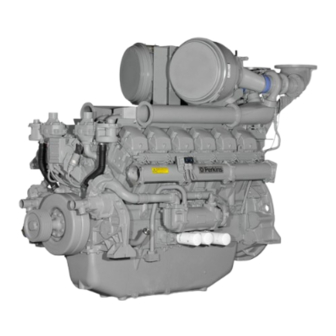
Page 13: Model Views
Product Information Section Model Views Model Views i03754026 Model View Illustrations 4012-46A The following model views show typical features of the engine. Due to individual applications, engines may appear different from the Illustrations. Note: Only serviced components are identified on... - Page 14 SEBU8191-01 Product Information Section Model Views g02090055 Illustration 10 Typical example Left side view of engine (1) Radiator cap (6) Air shutoff valve (11) Oil drain plug (2) Thermostat housing (7) Timing inspection hole (12) Oil level gauge (3) Coolant temperature switch (8) Inspection covers for crankcase (13) Oil filler (4) Air cleaner...
- Page 15 Bank A cylinders are on the right-hand side of the engine. Bank B cylinders are on the left-hand side of The 4012-46A Engine model is designed for power the engine. To determine the left and right sides of generation. The engine is available with turbocharged the engine, stand behind the flywheel and face the...
- Page 16 Refer to this Operation and Maintenance Manual, “Maintenance Interval Schedule” for more g01210840 Illustration 12 information on maintenance items. 4012-46A Engine model (A) Bank (B) Bank (X) Inlet valves (Y) Exhaust valves Table 1 4012-46A Engine Specifications...
-
Page 17: Product Identification Information
Plate Locations and Film TAG1 TAG2 Locations TAG3 TWG2 Engine Identification TWG3 Perkins engines are identified by an engine serial TRG1 number. TEG2 A typical example of an engine serial number is TEG3 DGB M**** U00001V. TRW2 Made in Stafford... - Page 18 SEBU8191-01 Product Information Section Product Identification Information Serial Number Plate g01229580 Illustration 14 g01266904 Illustration 13 The location of the serial number plate for vee-form engines Serial number plate The serial number plate (1) on a vee-form engine is located on the rear face of the cylinder block (bank The engine serial number plate contains the following A).
-
Page 19: Operation Section
fixtures obsolete. If alterations are made, ensure Engine Lifting that correct lifting devices are provided. Consult your Perkins dealer or your Perkins distributor for information regarding fixtures for correct engine lifting. NOTICE Never bend the eyebolts and the brackets. Only load i03781209 the eyebolts and the brackets under tension. -
Page 20: Features And Controls
SEBU8191-01 Operation Section Features and Controls Features and Controls i02415217 Monitoring System The engine is equipped with sensors or switches to monitor the following parameters: • Coolant temperature (Switch) • Oil pressure (Switch) • Intake manifold boost pressure (Sensor) • Exhaust temperature (if equipped) •... - Page 21 SEBU8191-01 Operation Section Features and Controls Coolant Temperature Switches Speed Sensor g01231514 g01231517 Illustration 18 Illustration 20 Coolant temperature switch Speed sensor The coolant temperature switches (2) monitor the The speed sensor (4) should be serviced at engine coolant temperature. The switches are the required maintenance interval.
- Page 22 SEBU8191-01 Operation Section Features and Controls Engine Oil Pressure Switch g01278615 Illustration 21 Engine oil pressure switch The engine oil pressure switch (5) is mounted in the main oil gallery. The engine oil pressure switches are supplied for connecting to an OEM supplied panel (1). Overspeed Sensor g01231518 Illustration 22...
-
Page 23: Engine Starting
SEBU8191-01 Operation Section Engine Starting Engine Starting b. Turn the keyswitch to the START position. Hold the keyswitch in this position until the oil pressure gauge indicates 100 kPa (14.5040 psi). Continue to hold the keyswitch i02415220 in the START position for an additional 10 Before Starting Engine seconds. - Page 24 SEBU8191-01 Operation Section Engine Starting i02415223 Cold Weather Starting Do not use aerosol types of starting aids such as ether. Such use could result in an explosion and personal injury. Startability will be improved at temperatures below +10 °C (+50 °F) from the use of a jacket water heater or extra battery capacity.
-
Page 25: Engine Operation
Fuel Conservation Practices i02415225 Engine Operation The efficiency of the engine can affect the fuel economy. Perkins design and technology in manufacturing provides maximum fuel efficiency in all applications. Follow the recommended procedures Correct operation and maintenance are key factors... -
Page 26: Engine Stopping
SEBU8191-01 Operation Section Engine Stopping Engine Stopping i02415231 After Stopping Engine i02415227 Stopping the Engine Note: Before you check the engine oil, do not operate the engine for at least 10 minutes in order to allow the engine oil to return to the oil pan. Note: Individual applications will have different •... -
Page 27: Maintenance Section
Refer to the OEM specifications for the capacity the American Petroleum Institute (API) is recognized of the auxiliary oil filter. by Perkins. For detailed information about this system, see the latest edition of the “API publication Cooling System No. - Page 28 DHD-1 oils are designed to control the harmful effects of soot with improved wear resistance The oil CD-2 is for a two-cycle diesel engine. Perkins does not and improved resistance to plugging of the oil filter. sell engines that utilize CD-2 oil.
- Page 29 TBN. These deposits can lead to a loss for conditions that demand a premium oil. Your of control of the oil consumption and to the polishing Perkins dealer or your Perkins distributor has specific of the cylinder bore. guidelines for optimizing oil change intervals.
- Page 30 Re-refined base stock oils are acceptable for additives in oil. It is not necessary to use aftermarket use in Perkins engines if these oils meet the additives in order to achieve the maximum service life performance requirements that are specified by of the engine or rated performance.
- Page 31 SEBU8191-01 Maintenance Section Refill Capacities • To achieve the best performance from a Perkins Cetane number _________ ______________________________ engine, conform to the following guidelines: • Viscosity 1.5 to 5.0 cSt at 40 °C (104 °F) ___________ • Select the correct oil, or a commercial oil that meets •...
- Page 32 These fuel specifications are considered acceptable Table 11 for issues of warranty. However, these fuels may Perkins Specifications for Distillate Diesel Fuel reduce the life of the engine, the maximum power of Specifications Requirements ASTM Test the engine and the fuel efficiency of the engine.
- Page 33 (Table 11, contd) NOTICE Copper Strip No. 3 maximum “D130” Operating with fuels that do not meet the Perkins rec- Corrosion ommendations can cause the following effects: Start- 10% at 282 °C ing difficulty, poor combustion, deposits in the fuel in- (540 °F)
- Page 34 • European distillate diesel fuel specification EN590: Perkins recommend the use of oil analysis in order 2010 includes up B7 (7 percent) biodiesel. to check the quality of the engine oil if biodiesel fuel is used.
- Page 35 SEBU8191-01 Maintenance Section Refill Capacities Perkins strongly recommended that seasonally operated engines have the fuel systems, including NOTICE fuel tanks, flashed with conventional diesel fuel Never operate an engine without water temperature before prolonged shutdown periods. An example of regulators in the cooling system. Water temperature an application that should seasonally flush the fuel...
- Page 36 • Reduction of heat transfer Coolant Recommendations • Leakage of the water pump seal The following two coolants are used in Perkins diesel • Plugging of radiators, coolers, and small passages engines: Preferred – Perkins Extended Life Coolant (ELC) Glycol Acceptable –...
- Page 37 Correct additions to the Extended Life above 43 °C (109.4 °F) and below 0 °C (32 °F) due Coolant to seasonal variations consult your Perkins dealer or your Perkins distributor for the correct level of NOTICE protection. Use only Perkins products for pre-mixed or concen- trated coolants.
- Page 38 8. Repeat Steps 6 and 7 until the system is Perkins engine cooling systems should be tested completely clean. at 500 hour intervals for the concentration of Supplemental Coolant Additive (SCA). 9. Fill the cooling system with the Perkins Premixed ELC.
- Page 39 SEBU8191-01 Maintenance Section Refill Capacities Additions of SCA are based on the results of the test. Table 20 is an example for using the equation that An SCA that is liquid may be needed at 500 hour is in Table 19. intervals.
-
Page 40: Maintenance Interval Schedule
SEBU8191-01 Maintenance Section Maintenance Interval Schedule Governor Actuator - Check ........64 i03789769 Speed Sensor - Clean/Inspect ......68 Maintenance Interval Schedule Every 5000 Service Hours Fuel Injector - Inspect/Adjust ........ 60 When Required Every 7500 Service Hours Battery - Replace ..........43 Battery or Battery Cable - Disconnect .... -
Page 41: Every 500 Service Hours Or 1 Year Actuator Control Linkage - Lubricate
SEBU8191-01 Maintenance Section Actuator Control Linkage - Lubricate i02471679 i02415235 Actuator Control Linkage - Aftercooler Core - Clean/Test Lubricate 1. Remove the core. Refer to the OEM information for the correct procedure. Personal injury can result from air pressure. Personal injury can result without following prop- er procedure. -
Page 42: Initial 100 Service Hours Alternator Pulley - Check
7. Dry the core with compressed air. Direct the air in the reverse direction of the normal flow. Perkins recommends a scheduled inspection of the alternator. Inspect the alternator for loose 8. Inspect the core in order to ensure cleanliness. -
Page 43: Battery - Replace
SEBU8191-01 Maintenance Section Battery - Replace 2. Turn off any battery chargers. Disconnect any battery chargers. 3. The NEGATIVE “-” cable connects the NEGATIVE “-” battery terminal to the NEGATIVE “-” terminal on the starting motor. Disconnect the cable from the NEGATIVE “-”... -
Page 44: Battery Or Battery Cable - Disconnect
SEBU8191-01 Maintenance Section Battery or Battery Cable - Disconnect 2. Check the condition of the electrolyte with a 7. Proceed with necessary system repairs. suitable battery tester. 8. In order to connect the battery, connect the 3. Install the caps. positive connection before the negative connector. - Page 45 SEBU8191-01 Maintenance Section Belts - Inspect/Adjust/Replace Removal of the Fan Drive Belts 9. Install the guards (not shown). 10. Restore the electrical supply to the engine. Adjustment 1. If necessary, isolate the electrical supply to the engine. Loosen the fasteners for the air pipes and remove the guards.
-
Page 46: Belts - Inspect/Adjust/Replace
SEBU8191-01 Maintenance Section Belts - Inspect/Adjust/Replace 7. Stop the engine. Refer to Operation and Maintenance Manual, “Stopping the Engine” for the correct procedure. 8. If necessary, isolate the electrical supply to the engine. Loosen the fasteners for the air pipes and remove the guards. -
Page 47: Every 12 000 Service Hours Or 6 Years Cooling System Coolant (Elc) - Change
SEBU8191-01 Maintenance Section Cooling System Coolant (ELC) - Change i03845643 Cooling System Coolant (ELC) - Change NOTICE Care must be taken to ensure that fluids are contained during performance of inspection, maintenance, test- ing, adjusting and repair of the product. Be prepared to collect the fluid with suitable containers before open- ing any compartment or disassembling any compo- nent containing fluids. - Page 48 Dispose of used engine coolant or recycle. Various methods have been proposed to reclaim used coolant for reuse in engine cooling systems. The full distillation procedure is the only method acceptable by Perkins to g01211160 reclaim the coolant. Illustration 37...
-
Page 49: Cooling System Coolant - Change
SEBU8191-01 Maintenance Section Cooling System Coolant - Change 3. Fill the cooling system with clean water. If equipped, loosen the vent screws (4) in the aftercoolers. Fill the cooling system until coolant free of air flows from the vent screws. Tighten the vent screws securely. - Page 50 SEBU8191-01 Maintenance Section Cooling System Coolant - Change • The oil has entered the cooling system and the coolant is contaminated. • The fuel has entered the cooling system and the coolant is contaminated. Note: When the cooling system is cleaned, only clean water is needed when the inhibitor is drained and replaced.
- Page 51 Do not fill the cooling system faster than 5 L procedure is the only method acceptable by Perkins (1.3 US gal) per minute to avoid air locks. Engines Company LTD to reclaim the coolant.
-
Page 52: Cooling System Coolant Level - Check
SEBU8191-01 Maintenance Section Cooling System Coolant Level - Check 5. Clean the cooling system filler cap (1) and inspect the seal (2). If the seal is damaged, discard the old filler cap and install a new filler cap. If the seal is not damaged, use a suitable pressurizing pump in order to pressure test the filler cap. -
Page 53: Engine - Clean
SEBU8191-01 Maintenance Section Engine - Clean i02415247 i03781630 Engine - Clean Engine Air Cleaner Element - Replace NOTICE Personal injury or death can result from high volt- Never run the engine without an air cleaner element age. installed. Never run the engine with a damaged air cleaner element. -
Page 54: Engine Air Cleaner Service Indicator - Inspect
SEBU8191-01 Maintenance Section Engine Air Cleaner Service Indicator - Inspect Service Indicator Reset 3. Install a new element (2) into the housing (1). Install the cover (4) and tighten securing clamp (3). i02415251 Engine Air Cleaner Service Indicator - Inspect Service Indicator Check Check the service indicators. -
Page 55: Engine Oil Filter (Auxiliary) - Change
SEBU8191-01 Maintenance Section Engine Mounts - Inspect • Loose bolts • Deterioration of the isolators Ensure that the mounting bolts are tightened to the correct torque. Ensure that the isolators are free of oil and contamination. Inspect the isolators for deterioration. Ensure that the bolts for the isolators are tightened to the correct torque. -
Page 56: Engine Oil Level - Check
SEBU8191-01 Maintenance Section Engine Oil Level - Check The changeover valve (1) has three positions. • (A) The oil flow is to both oil filters. • (B) The oil flow is to the left-hand oil filter. • (C) The oil flow is to the right-hand oil filter. 1. -
Page 57: Engine Oil Sample - Obtain
A trend can be established by analyzing the results of the oil sampling. Each individual operator can develop a service program for the engine. Note: Perkins Engines Stafford must agree to the Hot oil and hot components can cause personal maintenance schedule. - Page 58 Refer to Operation and NOTICE Maintenance Manual, “Refill Capacities” for more Perkins oil filters are manufactured to Perkins Engine information. Company LTD specifications. Use of an oil filter that is not recommended by Perkins Engine Company LTD NOTICE could result in severe damage to the engine.
-
Page 59: Engine Valve Lash - Inspect/Adjust
Refer to the Service Manual or your au- 5. Remove the engine oil level gauge (2) in order to thorized Perkins dealer or your Perkins distributor for check the oil level. Maintain the oil level between the complete valve lash adjustment procedure. -
Page 60: Fuel System - Prime
Perkins distributor for the complete proce- dure in order to inspect or adjust the fuel injectors. Operation of Perkins engines with fuel injectors that have not been inspected or adjusted can reduce en- gine efficiency, and also reduce engine component life. -
Page 61: Fuel System Filter - Replace
SEBU8191-01 Maintenance Section Fuel System Filter - Replace 8. Operate the handle (4) until fuel that is free of air flows from the connection (5). 9. Tighten the connection (5). 10. Loosen connections (6) and (8). 11. Operate the handle (4) until fuel that is free of air flows from the connection (6) and (8). -
Page 62: Fuel System Primary Filter/Water Separator
SEBU8191-01 Maintenance Section Fuel System Primary Filter/Water Separator - Drain NOTICE Ensure that the engine is stopped before any servicing or repair is performed. NOTICE The water separator can be under suction during nor- mal engine operation. Ensure that the drain valve is tightened securely to help prevent air from entering the fuel system. -
Page 63: Fuel Transfer Pump (Lift Pump) - Inspect
SEBU8191-01 Maintenance Section Fuel Transfer Pump (Lift Pump) - Inspect Fuel Tank If a bulk storage tank has been refilled or moved recently, allow adequate time for the sediment to Fuel quality is critical to the performance and to the settle before filling the engine fuel tank. -
Page 64: Hoses And Clamps - Inspect/Replace
SEBU8191-01 Maintenance Section Governor Actuator - Check 6. Remove the fuel lift pump (2). If you inspect the engine in operation, always use the proper inspection procedure in order to avoid 7. Remove the joint from the lift pump (2). Discard a fluid penetration hazard. -
Page 65: Overhaul (Major)
Maintenance Section Overhaul (Major) The coolant system and the hoses for the coolant i02461950 system are not usually supplied by Perkins. The Overhaul (Major) following text describes a typical method of replacing coolant hoses. Refer to the OEM information for further information on the coolant system and the hoses for the coolant system. -
Page 66: Overhaul (Top End)
SEBU8191-01 Maintenance Section Overhaul (Top End) • Engine mounted aftercoolers 1. Remove the rocker covers. • Camshafts 2. Refer to Systems Operation, Testing and Adjusting, “Valve Lash - Adjust”. • Camshaft followers 3. On all engine cylinders, record the clearance •... -
Page 67: Severe Service Application - Check
Refer to the standards for the engine or consult your Perkins dealer or your Perkins distributor in order to Pressurized water may also be used for cleaning. determine if the engine is operating within the defined The maximum water pressure for cleaning purposes parameters. -
Page 68: Speed Sensor - Clean/Inspect
SEBU8191-01 Maintenance Section Speed Sensor - Clean/Inspect Environmental Factors Table 24 Required Tools Ambient temperatures – The engine may be exposed to extended operation in extremely Part Tool Part Name Number cold environments or hot environments. Valve components can be damaged by carbon buildup if SE253 Crankshaft Turning Tool the engine is frequently started and stopped in very... -
Page 69: Starting Motor - Inspect
SEBU8191-01 Maintenance Section Starting Motor - Inspect 4. Use a soft, dry cloth in order to clean any debris from the sensor (2). Note: Do not use a wire brush in order to clean the sensor. Do not use abrasive material in order to clean the sensor. -
Page 70: Turbocharger - Inspect
Fouling of the turbine wheels replacement, refer to the Service Manual, or consult can contribute to loss of engine power and overall a Perkins distributor. loss of engine efficiency. 1. Remove the exhaust outlet piping and remove If a turbocharger fails during engine operation, the air inlet piping from the turbocharger. -
Page 71: Walk-Around Inspection
Excessive coolant leakage may indicate the need piping to the turbocharger housing. to replace a water pump. Refer to Operation and Maintenance Manual, “Water Pump - Inspect” for more information. If necessary, consult your Perkins i02415322 dealer or your Perkins distributor. Walk-Around Inspection •... -
Page 72: Water Pump - Inspect
SEBU8191-01 Maintenance Section Water Pump - Inspect i04326852 Water Pump - Inspect A failed water pump may cause severe engine overheating problems that could result in the following conditions: • Cracks in the cylinder head • A piston seizure • Other potential damage to the engine Note: The water pump seal is lubricated by the coolant in the cooling system. -
Page 73: Warranty Section
Emissions Warranty. Consult your authorized Perkins dealer or your authorized Perkins distributor in order to determine if your engine is emissions certified and if your engine is subject to an Emissions Warranty. - Page 74 SEBU8191-01 Index Section Index Engine Air Cleaner Service Indicator - Inspect..54 Service Indicator Check ........54 Service Indicator Reset........54 Actuator Control Linkage - Lubricate ..... 41 After Stopping Engine..........26 Engine Crankcase Breather - Clean...... 54 Aftercooler Core - Clean/Test ........ 41 Engine Description ..........
- Page 75 Maintenance Interval Schedule ......40 Normal Engine Starting Procedure ....23 Maintenance Section ..........27 Stopping the Engine ..........26 Model View Illustrations......... 13 4012-46A ............13 Model Views ............13 Monitoring System..........20 Mounting and Dismounting........9 Table of Contents............. 3 Turbocharger - Inspect ..........
- Page 76 SEBU8191-01 Index Section...
- Page 77 Product and Dealer Information Note: For product identification plate locations, see the section “Product Identification Information” in the Operation and Maintenance Manual. Delivery Date: Product Information Model: Product Identification Number: Engine Serial Number: Transmission Serial Number: Generator Serial Number: Attachment Serial Numbers: Attachment Information: Customer Equipment Number: Dealer Equipment Number:...
- Page 78 ©2011 Perkins Engines Company Limited Printed in U.K. All Rights Reserved...
Need help?
Do you have a question about the 4012-46A and is the answer not in the manual?
Questions and answers