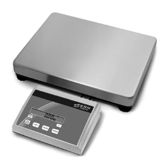
KERN FTB Service Manual

KERN FTB Service Manual

Compact scales platform balances and terminals
Table of Contents

Advertisement

GB
Platform Balances and Terminals
KERN FTB/FTC
KERN ITB/ITS/ITT
KERN KMB/KMS/KMT-TM
KERN & Sohn GmbH
Ziegelei 1
D-72336 Balingen-Frommern
E-Mail: info@kern-sohn.com
Service Manual
Compact Scales
Version 2.0
Tel: 0049-[0]7433- 9933-0
Fax: 0049-[0]7433-9933-149
Internet: www.kern-sohn.com
03/2007
Page 3

Advertisement

Table of Contents
loading

Summary of Contents for KERN FTB

  • Page 1 KERN & Sohn GmbH Ziegelei 1 Tel: 0049-[0]7433- 9933-0 D-72336 Balingen-Frommern Fax: 0049-[0]7433-9933-149 E-Mail: info@kern-sohn.com Internet: www.kern-sohn.com Service Manual Page 3 Compact Scales Platform Balances and Terminals KERN FTB/FTC KERN ITB/ITS/ITT KERN KMB/KMS/KMT-TM Version 2.0 03/2007...
  • Page 2: Table Of Contents

    Service concept ..........................Introducing the product group ......................Safety notes ............................. Compact scales, small platform FTB/FTC (weighing pan 200x240mm) ..........Scales with strain gauge weighing cells ..................... Scales with strain gauge weighing cell and IP65 protection ..............Display unit FTB ..........................
  • Page 3 Repair of terminals ......................... Important information ........................Disassembling/reassembling the terminal ..................Replacing the keypad overlay ......................Replacing the AC adapter........................Replacing the analog board......................Replacing the display mounting plate, display unit, and digital board ..........Repairing the OptionPac ........................Scale definition, settings and diagnostics ..................Accessing and using the technician menu ..................
  • Page 4: General

    The scales have been designed so that defective components can be replaced with just a few simple tools. Technician mode and supervisor mode will already be familiar to you, since this concept has already been used in other KERN & SOHN products.
  • Page 5: Introducing The Product Group

    Introducing the product group The product group comprises the following models, which are all covered by this manual: FTB, ITB, KMB-TM The FTB-,ITB-scales and the KMB-terminal possess basic weighing functions for simple weighing duties. They are IP65 versions. FTC, ITS, KMS-TM In addition to basic weighing functions, counting scales also have built-in functions for piece counting.
  • Page 6: Safety Notes

    Safety notes When carrying out service or repair work, always observe the following: • Before opening the scale, isolate it from the AC power line (pull out the plug). • The scales contain precision electronic components that are sensitive to elec- trostatic discharge.
  • Page 7: Compact Scales, Small Platform Ftb/Ftc (Weighing Pan 200X240Mm)

    Compact scales, small platform FTB/FTC (weighing pan 200x240mm) Scales with strain gauge weighing cells FTx/ITx-SH-e-0720...
  • Page 8 Item Qty. Description Order No. weighing pan 200 x 240 mm 21203071 rubber cushions 21203073 countersunk Torx screw M6 x 30 pan support plate 200 x 240 mm – housing, with small platform – keypad overlay Chap. 2.3 – 2.4 mounting plate and display unit (digital PCB with LCD and backlighting unit) Chap.
  • Page 9 Scales with strain gauge weighing cells (continued) FTx/ITx-SH-e-0720...
  • Page 10 Item Qty. Description Order No. adjustable foot Ø 44 mm (M10 x 0.75 mm) 21203434 countersunk Torx screw M4 x 12 bottom plate for small platform model – button head Torx screw M4 x 12 wide flange washer 4.3 x 20 overload spring overload stop adjustment screw (with certain production series only) countersunk Torx screw M6 x 16...
  • Page 11: Scales With Strain Gauge Weighing Cell And Ip65 Protection

    Scales with strain gauge weighing cell and IP65 protection FTx/ITx-SH-e-0720...
  • Page 12 Item Qty. Description Order No. packing for cover plate 21203235 cover plate – countersunk Torx screw M3 x 8 flange D = 100 mm – diaphragm 21203077 flange D = 58 mm – countersunk Torx screw M3 x 10 countersunk Torx screw M3 x 8 EMC clamp 21203480 * included in the small parts set (Chapter 4.5)
  • Page 13 Scales with strain gauge weighing cell and IP65 protection (continued) FTx/ITx-SH-e-0720...
  • Page 14 Item Qty. Description Order No. bottom plate for small platform model IP65 version 21203511 RS connector plate IP65 version (various types, depending on the equipment) – air supply/extraction filter 21203860 packing for RS connector plate 21203236 raised cheese head Torx screw M4 x 6 RS cable 460 mm IP65 21203717 pressure equalizer...
  • Page 15: Display Unit Ftb

    Display unit FTB FTx/ITx-SH-e-0720...
  • Page 16 Item Qty. Description Order No. keypad overlay for small platform model 22011400 display mounting plate (always order together with item 1) 21203120 21203134 backlighting unit 21203136 digital PCB with FLASH Memory Chip (soldered) 21204025 Torx oval head tapping screw 2.9 x 13 (red) * included in the small parts set (Chapter 4.5) see Chapter 9.4 for information on loading the software FTx/ITx-SH-e-0720...
  • Page 17: Display Unit Ftc

    Display unit FTC FTx/ITx-SH-e-0720...
  • Page 18 Item Qty. Description Order No. keypad overlay for small platform model 22011401 BC display mounting plate (always order together with item 1) 21203120 21203687 backlighting unit 21203137 Digital PCB with FLASH Memory Chip soldered 21204025 Torx oval head tapping screw 2.9 x 13 (red) * included in the small parts set (Chapter 4.5) see Chapter 9.4 for information on loading the software FTx/ITx-SH-e-0720...
  • Page 19: Compact Scales, Large Platform Ftb/Ftc (Weighing Pan 240X350Mm)

    Compact scales, large platform FTB/FTC (weighing pan 240x350mm) Scales with strain gauge weighing cell FTx/ITx-SH-e-0720...
  • Page 20 Item Qty. Description Order No. weighing pan 240 x 350 mm 21203072 rubber cushions 21203073 countersunk Torx screw M6 x 30 pan support plate 240 x 350 mm – housing, large platform – keypad overlay Chap. 3.3 – 3.4 mounting plate and display unit (digital PCB with LCD and backlighting unit) Chap.
  • Page 21 Scales with strain gauge weighing cell (continued) FTx/ITx-SH-e-0720...
  • Page 22 Item Qty. Description Order No. adjustable foot Ø 55 mm (M10 x 0.75 mm) 21203433 countersunk Torx screw M4 x 10 bottom plate for large platform model – button head Torx screw M5 x 12 wide flange washer 5.3 x 20 overload spring overload stop adjustment screw (with specific production series only) countersunk Torx screw M6 x 16...
  • Page 23 for scales with with AccuPac only: accu 14,4V NiMH (always order together with item 16) 22011349 battery connection cable – print charger NiMH 22011351 battery cable (charging PCB – analog PCB) 21203233 included in the small parts set (Chapter 4.5) ** see section 5.8 "Replacing the weighing cell"...
  • Page 24: Scales With Strain Gauge Weighing Cell And Ip65 Protection

    Scales with strain gauge weighing cell and IP65 protection FTx/ITx-SH-e-0720...
  • Page 25 Item Qty. Description Order No. packing for cover plate 21203235 cover plate – countersunk Torx screw M3 x 8 flange D = 100 mm – diaphragm 21203077 flange D = 58 mm – countersunk Torx screw M3 x 10 countersunk Torx screw M3 x 8 EMC clamp 21203480 * included in the small parts set (Chapter 4.5)
  • Page 26 Scales with strain gauge weighing cell and IP65 protection (continued) FTx/ITx-SH-e-0720...
  • Page 27 Item Qty. Description Order No. bottom plate for large platform model IP65 version 21203512 RS connector plate IP65 version (various types, depending on the equipment) – air supply/extraction filter 21203860 packing for RS connector plate 21203236 raised cheese head Torx screw M4 x 8 RS cable 460 mm IP65 21203717 pressure equalizer...
  • Page 28: Display Unit Ftb

    Display unit FTB FTx/ITx-SH-e-0720...
  • Page 29 Item Qty. Description Order No. keypad overlay for large platform model 22011404 display mounting plate (always order together with item 1) 21203120 21203134 backlighting unit 21203136 digital PCB with FLASH Memory Chip (soldered) 21204025 Torx oval head tapping screw 2.9 x 13 (red) * included in the small parts set (Chapter 4.5) see Chapter 9.5 for information on loading the software FTx/ITx-SH-e-0720...
  • Page 30: Display Unit Ftc

    Display unit FTC FTx/ITx-SH-e-0720...
  • Page 31 Item Qty. Description Order No. keypad overlay for large platform model 22011404 display mounting plate (always order together with item 1) 21203120 21203134 backlighting unit 21203136 digital PCB with FLASH Memory Chip (soldered) 21204025 Torx oval head tapping screw 2.9 x 13 (red) * included in the small parts set (Chapter 4.5) see Chapter 9.5 for information on loading the software FTx/ITx-SH-e-0720...
  • Page 32: Terminals

    Terminals KMB-TM terminal (ITB) FTx/ITx-SH-e-0720...
  • Page 33 Item Qty. Description Order No. base plate with seal attached 21255118 rubber foot 00200068 countersunk screw M4 x 12 Torx T20 bench AC adapter 8VA (always order together with item 5): EURO version 22011363 USA version 22011364 UK version 22011365 JAPAN version 22011366 Australian version...
  • Page 34: Kms-Tm Terminal (Its)

    KMS-TM terminal (ITS) FTx/ITx-SH-e-0720...
  • Page 35 Item Qty. Description Order No. base plate with seal attached 21255118 rubber foot 00200068 countersunk screw M4 x 12 Torx T20 bench AC adapter 8VA (always order together with item 5): EURO version 22011363 USA version 22011364 UK version 22011365 JAPAN version 22011366 Australian version...
  • Page 36: Kmt-Tm Terminal (Itt)

    KMT-TM terminal (ITT) FTx/ITx-SH-e-0720...
  • Page 37 Item Qty. Description Order No. base plate with seal attached 21255118 rubber foot 00200068 countersunk screw M4 x 12 Torx T20 bench AC adapter 8VA (always order together with item 5): EURO version 22011363 USA version 22011364 UK version 22011365 JAPAN version 22011366 Australian version...
  • Page 38: Optionpac

    OptionPac FTx/ITx-SH-e-0720...
  • Page 39 Item Qty. Description Order No. base plate with seal attached 21255118 rubber foot 00200068 countersunk screw M4 x 12 Torx T20 fillister head screw M5 x 12 PCB for NiMH storage battery charger circuit 22011451 fastening clamp for charging circuit board connecting cable charging circuit –...
  • Page 40: Small Parts Set

    Small parts set The small parts set comprises all the standard components (screws, washers, etc.) required for service work on scales and terminals. Qty. Description Order No. small parts set 21203404 countersunk Torx screw M3 x 8 – countersunk Torx screw M3 x 10 –...
  • Page 41: Replacing Components With Compact Scales

    Replacing components with compact scales Important notes This section describes how to change individual components of the compact scales. When doing this, please refer to the exploded view drawings and spare parts lists in Chapters 2 and 3. Important: After replacing components, a functional check of the scale must always be carried out.
  • Page 42: Replacing The Keypad Overlay

    Replacing the keypad overlay • Lift up the defective keypad overlay (if necessary carefully prying it up with a knife) and gently peel it off the scale. Caution: take care that the specification label is not damaged when the membrane is removed! •...
  • Page 43: Replacing The Charging Pcb

    against the wall of the housing. • Attach both plugs with connectors to the charging PCB and slide the PCB back it into the guide. • Replace the RS connector plate and secure with the screws. Note for scales with IP65 protection: Check that the seal of the connector plate is still correctly fastened to the housing. If it is not, the seal must be replaced as follows: Remove the existing seal from the housing so as to leave no trace.
  • Page 44: Replacing The Display Mounting Plate, Display Unit And Digital Pcb

    Replacing the display mounting plate, display unit and digital PCB The display mounting plate is located underneath the keypad membrane and is attached to the scale housing by 6 snaps. The display unit comprises the digital PCB, the liquid crystal display (LCD) and the backlighting unit. It is held in place on the mounting plate by snaps.
  • Page 45 Caution: On FTB the LC display is only held in the connector strip on one side. Because of this, for assembly of the PCB, the display, and the backlighting must be held together by hand, otherwise the backlighting may come out of the drilled holes in the PCB and be displaced! •...
  • Page 46: Replacing The Weighing Cell

    The adjustment screw is to be tightened until there is a gap between the screw and weighing cell according to the table below. Caution: Turning the screw too tightly can damage the weighing cell! Scale Color of overload spring Gap between adjustment screw and weighing cell FTB/FTC 3 kg 0.45 mm FTB/FTC 6 kg 0.45 mm FTB/FTC 15 kg white 0.25 mm...
  • Page 47 Assembly • Replace the bottom plate and the adjustable feet. • Scales without IP65 protection: Turn the scale the right way up, replace the pan support plate and secure it with the screws. Before finally tightening the screws, make sure that the pan support plate is aligned squarely with the scale housing.
  • Page 48: Repair Of Terminals

    Repair of terminals Important information When performing repairs please refer to the exploded view drawings and lists of spare parts in Chapter 4 of this manual. Important: After replacing components, a functional check of the terminal must always be carried out. 6.1.1 Safety and environment Whenever repairs are carried out, the following safety precautions must always be taken:...
  • Page 49: Replacing The Keypad Overlay

    Replacing the keypad overlay • Lift the defective keypad overlay by a corner and gently peel it off. • Carefully remove all traces of adhesive with, for example, a wooden or plastic scraper. Caution: Make sure not to damage the keypad membrane of KMT-TM terminals! •...
  • Page 50: Replacing The Display Mounting Plate, Display Unit, And Digital Board

    Replacing the display mounting plate, display unit, and digital board The display mounting plate is located underneath the keypad overlay and is attached to the scale housing by 6 snaps. The display unit comprises the digital PCB, the liquid crystal display (LCD) and the backlighting unit. It is held in place on the mounting plate and the housing by snaps and screws.
  • Page 51 • Peel the upper and lower protective films off the new LCD. • Carefully place the LCD onto the backlighting unit and ensure that the contact pins are correctly aligned with the socket strip(s). When correctly positioned, the ends of the LCD and the backlighting unit are flush. Use a flat object such as a ruler to exert a uniform pressure on the LCD and gently push it home.
  • Page 52: Repairing The Optionpac

    Repairing the OptionPac 6.7.1 Replacing the battery Note: This section relates only to terminals which have an OptionPac with built-in battery. • Remove the base plate of the OptionPac (8 screws, Torx T20). • Remove battery from wall of housing (attached by adhesive patch). If necessary, carefully insert a flat blade (knife or screwdriver) between battery and housing, then release AC adapter.
  • Page 53: Scale Definition, Settings And Diagnostics

    Scale definition, settings and diagnostics The menu of the compact scales and the terminals includes a special section dedicated to the service technician. The technician setup offers settings and procedures for maintenance and diagnostics. Accessing this part of the menu requires a special password while navigation within the technician menu is the same as with the user and supervsior menu (see User Manual).
  • Page 54: Technician Menu - Overview

    Technician menu – Overview The overview below shows the menu blocks holding additional settings dedicated to the technician (“SCALE”, “TERMINAL”). The settings available to the technician only are printed in boldface. The further menu blocks (“APPLICATION”, “COMMUNICATION” and “DIAGNOSTICS”) are similar to the ones in the supervisor setup (see User Manual) and are not shown below.
  • Page 55: Admissibility For Certification (Scale -> Metrology)

    Only the settings and procedures for the “SCALE” and “TERMINAL” menus that are available exclusively to service technicians are described here. The other menu options are described in the User Manual. Admissibility for certification ( SCALE –> Metrology ) The following settings are available: “no Appr”...
  • Page 56 7.7.1 Defining the scale type ( SCALE –> Scale Build –> Scale Type ) The following scale types are available “Single Range” Single-range scale. “2 Multi Interval” Scale with coarse range and 1 movable fine range. Automatic switching between the ranges in both directions.
  • Page 57: Setting The Geo Adjustment Value (Scale -> Geo Value)

    7.7.5 Choosing the resolution ( SCALE –> Scale Build –> Resolution ) The resolution must be specified when building a new scale using a terminal. Furthermore, the resolution has to be specified if the analog PCB is replaced, as its EEPROM is factory-set to a basic value. With compact scales FTx the resolution is indicated on the plate above the display and must be set to this value.
  • Page 58: Basic Calibration (Scale -> Calibration)

    7.10 Basic calibration ( SCALE –> Calibration ) The basic calibration uses the display unit 1 ( SCALE –> Display –> Unit 1 ). Procedure • Before calibration the geo adjustment value should be checked and corrected if necessary (chapter 7.8). It cannot be changed again subsequently.
  • Page 59: Defining Minweigh Value (Scale-> Minweigh)

    Procedure • Ensure that the preload for which the calibration zero point is to be moved is in place. • Start the function. You will see a prompt asking you if you really want to move the calibration zero point. The calibration zero point is moved when you confirm the prompt.
  • Page 60: Additional Information

    * with approved scales the overload display may only appear when the load is more then 9d above the maximum load ** for scales with IP65 protection degree (FTB) Note on linearity The linearity of certified or certifiable scales must be verified at 0%, 50% and 100% of the full load. Tolerances are given in the following calibration diagrams.
  • Page 61 Weighing range Readability e value Certification diagram 3 kg 1.0 g -0.5 -1.5 6 kg 2.0 g 15 kg 5.0 g 12.5 -2.5 -7.5 35 kg 10.0 g 60 kg 20.0 g FTx/ITx-SH-e-0720...
  • Page 62 8.1.2 Certifiable and certified compact scales with strain gauge load cells (premium) The following data apply to all certifiable or certified compact scales with premium strain gauge load cells. Scale capacity 6 kg 15kg 35kg 60kg Weighing range 3000* 6000* 15000* 35000* 60000*...
  • Page 63 Weighing range Readability e value Certification diagram 3 kg 0.5 g 0.75 0.50 0.25 -0.25 -0.50 -0.75 6 kg 1.0 g -0.5 -1.0 -1.5 15 kg 2.0 g 12.5 35 kg 5.0 g -2.5 -5.0 -7.5 60 kg 10.0 g FTx/ITx-SH-e-0720...
  • Page 64 * for scales with IP65 protection degree (FTB) Note on calibration It is recommended that non-certifiable scales are also calibrated under full load. If required, however, these can also be calibrated at less than full load (minimum approx. 25% of full load). The calibration tolerance given in the table applies to calibration under full load.
  • Page 65: Notes On Load Cell Capacities

    Notes on load cell capacities The following diagram is a schematic summary of the distribution of the total capacity of a load cell. Total capacity of load cell 100% Total Zero setting Extended Weighing range ("Range") preload range on power up nominal load Total capacity of load cell The total capacity of the load cell is the combined sum of the weighing range, the total preload, the zero setting range and any...
  • Page 66: Overview Of Load Cells And Preloads

    (kg) range support and weighing reserve (18% of (kg) weighing range) FTB/FTC 200 x 240 mm 3 kg 21203873 0.280 kg 0.540 kg 0.820 kg 1.180 kg 0.540 kg 5 kg 21203877* FTB/FTC...
  • Page 67: Table Of Geo Values

    Table of geo values Elevation above sea level in meters 1300 1625 1950 2275 2600 2925 3250 Geographical latitude in 1300 1625 1950 2275 2600 2925 3250 3575 the northern or southern Elevation above sea level in feet hemisphere in degrees 1060 2130 3200...
  • Page 68: Interface Data

    Interface data FTB/FTC compact scales and KMB-/KMS-/KMT-TM terminals (ITB/ITS/ITT) terminals are fitted as standard with one RS232C interface (DIN 66020; CCITT V24/V.28). They are optionally available with an additional interface (RS232, Ethernet, Digital I/O (only KMT-TM, ITT) or analog second scale interface (KMS-/KMT-TM,ITS/ITT and FTC)).
  • Page 69 Optional interface: RS232C and analog second scale COM1 (RS232) Analog second scale VCC (power supply +5V) 2) 4) +Excitation (+8.2 VDC) TxD 1 (transmit data) +Sense RxD 1 (receive data) shield –Sense GND (Signal ground) –Excitation +Signal –Signal Optional interface: RS232C and Digital I/O COM1 (RS232) COM2 (Digital I/O) TxD 1 (transmit data)
  • Page 70: Attaching Weighing Platforms

    Attaching weighing platforms All analog weighing platforms can be attached to the terminals if they conform to the required specifications (see chapter 8.5). A second weighing platform can be attached to terminals equipped with the optional analog interface (OptionPac). Compact two-scale systems can therefore be constructed using just one terminal. 8.6.1 Instructions on weighing cells Cells with or without SENSE lines...
  • Page 71 8.6.2 Preparing the connecting cable for the weighing platform Remove the insulation as shown on the left. 135 mm Note: For connecting to the analog option, only 100 mm 5 mm 15 mm of cable insulation should be removed. 8.6.3 Attaching the weighing platform to the terminal Before assembling, the terminal must first be discon- nected from the power supply!
  • Page 72 Secure the individual strands of the connecting cable on the connector. The pin 7-pin connector assignment is shown in the diagram opposite. The pins are marked as follows: Si = Signal, Ex = Excitation, Se = Sense. +Ex +Se +Si -Si -Se -Ex Attach the connector to the terminal.
  • Page 73: Software

    The various models of a particular series have identical software (e.g. FTB 6 kg and FTB 15 kg). On powering up, the scale carries out a display test in which the software version is also briefly displayed, e.g.: "4-1.1.07"...
  • Page 74: Error Messages After Service Work

    Error messages after service work In addition to the errors described in the operating instructions, the following error messages may also appear after carrying out service work: No calibration Err 6 This error only occurs after reinitializing the EAROM, i.e. after rectifying Error 53. Remedy: Recalibrate the scale in technician mode (Chapter 7).
  • Page 75: Loading New Scale Software Into Flash Memory

    Loading new scale software into Flash memory Loading new software into the flash memory chip requires a special program, the so-called FlashLoader for the Microsoft Windows ® operating system. The FlashLoader is used to load the software from the PC onto the scale. If for any reason this is not possible, the digital PCB on which the Flash Memory chip is soldered must be replaced (see Section 4/5 of this service manual).
  • Page 76 You will then be prompted to connect the interface cable to the serial interface of the scale. Answer the query on the loss of current data with "Proceed" to start loading the new software. You can still cancel the process at this point with "Cancel". De-energize scale or terminal (disconnect power plug) and confirm with "Proceed".

This manual is also suitable for:

ItbFtcIttKmbKmsKmt-tm ... Show all

Table of Contents