Table of Contents
Advertisement
Quick Links
SETUP & OPERATION MANUAL
FEATURES
Industrial rated quality and versatile design
allows for standard crosscuts, as well as bevels,
miters, and head swivels for rip cutting applica-
tions.
Powerful 2 HP 220V single phase (M1) or 3 HP
220V 3-phase (M2) TEFC motor.
Cast-iron frame, heavy steel column and sturdy
easy to assemble all-steel stand for perfect
alignment and stability.
Precision adjustable indexing with positive stops
at 90º, 45º and 22.5º.
See-through blade cover with anti-kickback at-
tachment and splitter.
Magnetic switch with overload protection and a
lock-out key to prevent unauthorized use.
Automatic mechanical brake stops the blade in
seconds upon shutdown.
Dual 4" dust ports above the table, and a 2" dust
port on the rear of the blade cover.
12" negative rake, multi-purpose combination
blade included.
Adjustable tension cutterhead / carriage return
spring to smoothly retract the motor and car-
riage back to the start position.
5/8" arbor with 1" spacer bushing included.
Replaceable steel guide ways.
Laser included.
SPECIFICATIONS
• Blade diameter
12" (305 mm)
• Arbor diameter (with 1" spacer bushing included)
5/8" (16 mm)
• Maximum depth of cut at 90°
3" (76 mm) - with 12" blade
2" (50 mm) - with 10" blade
• Maximum depth of cut at 45°
2" (50 mm) - with 12" blade
• Maximum crosscut capacity (with 12" blade)
16" (407 mm) - in 1" thick
• Maximum rip capacity (with 12" blade)
26 3/8" (670 mm)
• Dado capacity
13/16" (21 mm)
• Table height
36 3/4" (935 mm)
• Table size
27 1/2" x 35 3/8" (700 x 900 mm)
• Overall dimensions (l x w x h)
35 3/4" x 43 1/4" x 70 7/8" (900 x 1100 x 1800 mm)
• Motor M1
2 HP , 220 V, 1 Ph, 9.4 A
• Motor M2
3 HP , 230 V, 3 ph, 9.5 A
• Weight (shipping / net)
580 lbs (263 kg) / 396 lbs (180 kg)
Version
2_Revision
1 - February 2016
#
#
© Copyright General International
12" RADIAL ARM SAW
MODEL
50-755 M1
#
Advertisement
Table of Contents

Related Manuals for General International 50-755 M1


Summary of Contents for General International 50-755 M1
- Page 1 2 HP , 220 V, 1 Ph, 9.4 A • Motor M2 3 HP , 230 V, 3 ph, 9.5 A 50-755 M1 • Weight (shipping / net) 580 lbs (263 kg) / 396 lbs (180 kg) Version 2_Revision 1 - February 2016 © Copyright General International...
- Page 2 GENERAL® INTERNATIONAL 8360 Champ-d’Eau, Montreal (Quebec) Canada H1P 1Y3 Telephone (514) 326-1161 • Fax (514) 326-5555 • www.general.ca THANK YOU for choosing this General® International model 50-755 12” radial arm saw. This radial arm has been carefully tested and inspected before shipment and if properly used and maintained, will provide you with years of reliable service.
- Page 3 GENERAL INTERNATIONAL WARRANTY ® All component parts of General International and Excalibur by General International products ® ® are carefully inspected during all stages of production and each unit is thoroughly inspected upon completion of assembly. Limited Lifetime Warranty Because of our commitment to quality and customer satisfaction, General International agrees to ®...
-
Page 4: Table Of Contents
TABLE OF CONTENTS Rules for safe operation ..................... 5 Electrical requirements ...................... 6 Identification of main parts and components ..............7 Unpacking .......................... 8 Basic functions ........................8 Placement within the shop ....................9 Assembly instructions ....................9-16 Assembling the stand ............................9 Installing the machine on the stand ...................... -
Page 5: Rules For Safe Operation
RULES FOR SAFE OPERATION To help ensure safe operation, please take a moment to learn the machine’s applications and limitations, as well as potential hazards. General International disclaims any real or implied warranty and holds itself ® harmless for any injury that may result from the improper use of its equipment. 1. -
Page 6: Electrical Requirements
ELECTRICAL REQUIREMENTS BEFORE CONNECTING THE MACHINE TO THE POWER SOURCE, VERIFY THAT THE VOLTAGE OF YOUR POWER SUPPLY CORRESPONDS WITH THE VOLTAGE SPECIFIED ON THE MOTOR I.D. NAMEPLATE. A POWER SOURCE WITH GREATER VOLTAGE THAN NEEDED CAN RESULT IN SERIOUS INJURY TO THE USER AS WELL AS DAMAGE TO THE MACHINE. -
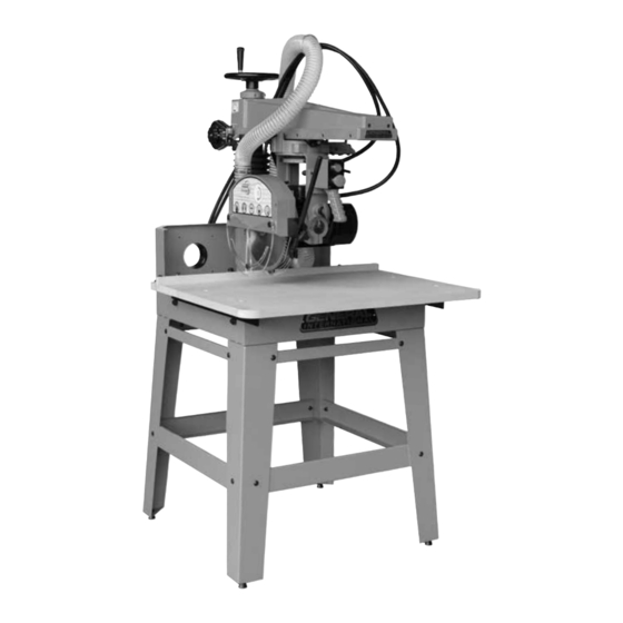
Page 7: Identification Of Main Parts And Components
IDENTIFICATION OF MAIN PARTS AND COMPONENTS STAND DUST HOSE WORK TABLE DUST PORT SUPPORT ON/OFF SWITCH ADJUSTABLE TENSION RETURN SPRING ANTI-KICKBACK FINGERS BLADE HEIGHT ADJUSTMENT HANDWHEEL SEE-THROUGH BLADE COVER... -
Page 8: Unpacking
UNPACKING Carefully unpack and remove the unit and its components from the box and check for missing or damaged items as per the list of contents below. NOTE: PLEASE REPORT ANY DAMAGED OR MISSING ITEMS TO YOUR GENERAL® INTERNATIONAL DISTRIBUTOR IMMEDIATELY. LIST OF CONTENTS WASHER (SMALLER) ............... -
Page 9: Placement Within The Shop
PLACEMENT WITHIN THE SHOP / SAFETY ZONE THIS RADIAL ARM SAW MODEL 50-755 IS HEAVY. DO NOT OVER-EXERT. A HOIST OR FORKLIFT WITH STRAPS SHOULD BE USED TO LIFT THIS MACHINE. TO LIMIT THE RISK OF SERIOUS INJURY OR DAMAGE TO THE MACHINE, ANY EQUIP- MENT USED TO LIFT THIS MACHINE SHOULD HAVE A RATED CAPACITY IN EXCESS OF 396 LBS (180 KG). - Page 10 BEFORE ASSEMBLING, MAKE SURE THAT THE SWITCH IS IN THE ”OFF” POSITION AND THAT THE POWER CORD IS UNPLUGGED. DO NOT PLUG IN OR TURN ON THE MACHINE UNTIL YOU HAVE COMPLETED THE ASSEMBLY AND INSTALLATION STEPS DESCRIBED IN THIS SECTION OF THE MANUAL. ASSEMBLING THE STAND (CONTINUED) Secure another leg to the cross brace by hand tight- Repeat step 2.
-
Page 11: Installing The Machine On The Stand
BEFORE ASSEMBLING, MAKE SURE THAT THE SWITCH IS IN THE ”OFF” POSITION AND THAT THE POWER CORD IS UNPLUGGED. DO NOT PLUG IN OR TURN ON THE MACHINE UNTIL YOU HAVE COMPLETED THE ASSEMBLY AND INSTALLATION STEPS DESCRIBED IN THIS SECTION OF THE MANUAL. ASSEMBLING THE STAND (CONTINUED) 11. -
Page 12: Installing The Handwheel Handle
BEFORE ASSEMBLING, MAKE SURE THAT THE SWITCH IS IN THE ”OFF” POSITION AND THAT THE POWER CORD IS UNPLUGGED. DO NOT PLUG IN OR TURN ON THE MACHINE UNTIL YOU HAVE COMPLETED THE ASSEMBLY AND INSTALLATION STEPS DESCRIBED IN THIS SECTION OF THE MANUAL. INSTALLING THE MACHINE ON THE STAND (CONTINUED) Slip appropriate lifting straps in the 4 lifting hooks C. -
Page 13: Installing The Blade
BEFORE ASSEMBLING, MAKE SURE THAT THE SWITCH IS IN THE ”OFF” POSITION AND THAT THE POWER CORD IS UNPLUGGED. DO NOT PLUG IN OR TURN ON THE MACHINE UNTIL YOU HAVE COMPLETED THE ASSEMBLY AND INSTALLATION STEPS DESCRIBED IN THIS SECTION OF THE MANUAL. INSTALLING THE BLADE There are a variety of different types of blades on the market to suit various cutting applications. -
Page 14: Installing The Batteries In The Laser
INSTALLING THE BLADE (CONTINUED) Remove the arbor nut by turning it clockwise with a Remove the laser. 19 mm wrench and by immobilising the arbor with Note: to install or replace the batteries see section "Install- an 8 mm Allen key. ing the batteries in the laser". -
Page 15: Installing The Control Box
BEFORE ASSEMBLING, MAKE SURE THAT THE SWITCH IS IN THE ”OFF” POSITION AND THAT THE POWER CORD IS UNPLUGGED. DO NOT PLUG IN OR TURN ON THE MACHINE UNTIL YOU HAVE COMPLETED THE ASSEMBLY AND INSTALLATION STEPS DESCRIBED IN THIS SECTION OF THE MANUAL. INSTALLING THE ELECTRICAL BOX Remove the 2 screws at the back of the machine Align the electrical box mounting holes with the... -
Page 16: Installing The Riving Knife
BEFORE ASSEMBLING, MAKE SURE THAT THE SWITCH IS IN THE ”OFF” POSITION AND THAT THE POWER CORD IS UNPLUGGED. DO NOT PLUG IN OR TURN ON THE MACHINE UNTIL YOU HAVE COMPLETED THE ASSEMBLY AND INSTALLATION STEPS DESCRIBED IN THIS SECTION OF THE MANUAL. INSTALLING THE RIVING KNIFE Remove the two screws and washers located in Secure the riving knife A to the blade cover with... -
Page 17: Main On/Off Magnetic Switch
MAKE SURE THE MACHINE HAS BEEN TURNED OFF AND UNPLUGGED FROM THE POWER SOURCE BEFORE PERFORM- ING ANY MAINTENANCE OR ADJUSTMENTS. MAIN ON/OFF MAGNETIC SWITCH This machine is equipped with a magnetic safety switch designed to protect the unit and the user from power surges, power outages and unwanted or unin- tentional start-up. -
Page 18: Positioning The Cutter Head On The Arm
MAKE SURE THE MACHINE HAS BEEN TURNED OFF AND UNPLUGGED FROM THE POWER SOURCE BEFORE PERFORM- ING ANY MAINTENANCE OR ADJUSTMENTS. POSITIONING OF THE CUTTER HEAD ON THE ARM Loosen the lock lever A. Place the cutter head on the radial arm as per the desired position and retighten the lever A. -
Page 19: Pivoting The Cutter Head For Bevel Cross Cutting
MAKE SURE THE MACHINE HAS BEEN TURNED OFF AND UNPLUGGED FROM THE POWER SOURCE BEFORE PERFORM- ING ANY MAINTENANCE OR ADJUSTMENTS. PIVOTING THE CUTTER HEAD FOR BEVEL CROSS CUTTING Unplug the machine from the power source. Dis- Using the graduated scale C as a reference, pivot the connect the cutter head from the return spring. -
Page 20: Adjusting The Return Spring Tension
MAKE SURE THE MACHINE HAS BEEN TURNED OFF AND UNPLUGGED FROM THE POWER SOURCE BEFORE PERFORM- ING ANY MAINTENANCE OR ADJUSTMENTS. ADJUSTING THE RETURN SPRING TENSION To increase return spring tension, push up on lever A To decrease tension, push up lever B while turning A while turning knob B counterclockwise. -
Page 21: Connecting To A Dust Collector
CONNECTING TO A DUST COLLECTOR ALWAYS TURN ON THE DUST COLLECTOR BEFORE STARTING THE SAW AND ALWAYS STOP THE SAW BEFORE TURNING OFF THE DUST COLLECTOR. Dual 4” dust ports are provided to accommodate con- nection to a dust collector (not included). Be sure to use appropriate sized hose and fittings (not included). - Page 22 MAKE SURE THE MACHINE HAS BEEN TURNED OFF AND UNPLUGGED FROM THE POWER SOURCE BEFORE PERFORM- ING ANY MAINTENANCE OR ADJUSTMENTS. CUTTING THE KERF IN THE WORK TABLE (CONTINUED) Loosen the cutter head lock lever. Position the cutter head at the end of the arm, then retighten the lever to lock the cutter head in position.
-
Page 23: Types Of Cuts
TYPES OF CUTS Cross cutting NEVER USE THE SAW WITHOUT ALL GUARDS AND COVERS IN PLACE. BEFORE STARTING THE SAW BE SURE THAT THE BLADE IS NOT ALREADY IN CONTACT WITH THE WORKPIECE. Install the fence A as shown and lock it by retight- Unlock the cutter head and position it at the end of the arm. - Page 24 MAKE SURE THE MACHINE HAS BEEN TURNED OFF AND UNPLUGGED FROM THE POWER SOURCE BEFORE PERFORM- ING ANY MAINTENANCE OR ADJUSTMENTS. Inboard ripping (continued) NEVER USE THE SAW WITHOUT ALL GUARDS AND COVERS IN PLACE. BEFORE STARTING THE SAW BE SURE THAT THE BLADE IS NOT ALREADY IN CONTACT WITH THE WORKPIECE.
-
Page 25: Maintenance
WHENEVER A RIP CUT IS COMPLETED, TURN OFF THE SAW AND WAIT FOR THE BLADE TO COME TO A COMPLETE STOP BEFORE REACHING IN TO REMOVE THE WORKPIECE OR THE WASTE MATERIAL. Bevel cutting NEVER USE THE SAW WITHOUT ALL GUARDS AND COVERS IN PLACE. BEFORE STARTING THE SAW BE SURE THAT THE BLADE IS NOT ALREADY IN CONTACT WITH THE WORKPIECE. - Page 26 MAKE SURE THE MACHINE HAS BEEN TURNED OFF AND UNPLUGGED FROM THE POWER SOURCE BEFORE PERFORM- ING ANY MAINTENANCE OR ADJUSTMENTS. ADJUSTING THE WORK TABLE PARALLEL TO THE CUTTER HEAD (CONTINUED) Unlock the cutter head by loosening the lever B. Pull back on knob C.
-
Page 27: Squaring The Blade To The Table
MAKE SURE THE MACHINE HAS BEEN TURNED OFF AND UNPLUGGED FROM THE POWER SOURCE BEFORE PERFORM- ING ANY MAINTENANCE OR ADJUSTMENTS. ADJUSTING THE WORK TABLE PARALLEL TO THE CUTTER HEAD (CONTINUED) Loosen the bolts C located on both sides of the ta- 10. -
Page 28: Squaring The Blade To The Fence
MAKE SURE THE MACHINE HAS BEEN TURNED OFF AND UNPLUGGED FROM THE POWER SOURCE BEFORE PERFORM- ING ANY MAINTENANCE OR ADJUSTMENTS. SQUARING THE BLADE TO THE TABLE (CONTINUED) Place a square against the blade. If an ajustment Unlock the blade cover by loosening lever D then is required, then go to the next step. -
Page 29: Adjusting The Graduated Scale For Inboard Ripping
MAKE SURE THE MACHINE HAS BEEN TURNED OFF AND UNPLUGGED FROM THE POWER SOURCE BEFORE PERFORM- ING ANY MAINTENANCE OR ADJUSTMENTS. SQUARING THE BLADE TO THE FENCE (CONTINUED) 90° Place a square on the work table. Then place a straight edge against the square and against the blade. -
Page 30: Cutter Head Bearing Adjustment
MAKE SURE THE MACHINE HAS BEEN TURNED OFF AND UNPLUGGED FROM THE POWER SOURCE BEFORE PERFORM- ING ANY MAINTENANCE OR ADJUSTMENTS. CUTTER HEAD BEARING ADJUSTMENT The cutter head bearings have been adjusted at the factory, therefore, except in some rare cases (important mainte- nance, improper handling or rough transport) no further adjustments are required. -
Page 31: Adjusting The Cutter Head Arm
ADJUSTING THE BASE (CONTINUED) Loosen the 2 bolts C using a 13 mm wrench to re- Loosen the 2 bolts C using a 13 mm wrench to re- duce clamping tension on the column for smooth- duce clamping tension on the column for smooth- er cutter head height adjustments. -
Page 32: Parts List & Diagrams
DIAGRAM A TABLE AND STAND - 50-755... - Page 33 PARTS LIST A TABLE AND STAND - 50-755 IMPORTANT: When ordering replacement parts, always give the model number, serial number of the machine and part number. Also a brief description of each item and quantity desired. PART NO. REF. NO. DESCRIPTION SPECIFICATIONS 50755-A01...
- Page 34 DIAGRAM B COLUMN - 50-755 IMPORTANT: When ordering replacement parts, always give the model number, serial number of the machine and part number. Also a brief description of each item and quantity desired. PART NO. REF. NO. DESCRIPTION SPECIFICATIONS 50755-B01 50102010 CAP SCREW M8 X 1.25P X 16L...
- Page 35 DIAGRAM C RADIAL ARM - 50-755 IMPORTANT: When ordering replacement parts, always give the model number, serial number of the machine and part number. Also a brief description of each item and quantity desired. PART NO. REF. NO. DESCRIPTION SPECIFICATIONS 50755-C01 50102023 CAP SCREW...
- Page 36 DIAGRAM D MOTOR BRACKET - 50-755...
- Page 37 PARTS LIST D MOTOR BRACKET - 50-755 IMPORTANT: When ordering replacement parts, always give the model number, serial number of the machine and part number. Also a brief description of each item and quantity desired. PART NO. REF. NO. DESCRIPTION SPECIFICATIONS 50755-D01 50101066...
- Page 38 PARTS LIST D MOTOR BRACKET - 50-755 IMPORTANT: When ordering replacement parts, always give the model number, serial number of the machine and part number. Also a brief description of each item and quantity desired. PART NO. REF. NO. DESCRIPTION SPECIFICATIONS 50755-D50 50102047...
- Page 39 PARTS LIST E MOTOR AND BLADE - 50-755...
- Page 40 PARTS LIST E MOTOR & BLADE - 50-755 IMPORTANT: When ordering replacement parts, always give the model number, serial number of the machine and part number. Also a brief description of each item and quantity desired. PART NO. REF. NO. DESCRIPTION SPECIFICATIONS 50755-E01...
- Page 41 NOTES...
-
Page 42: Contact Information
8360 Champ-d’Eau, Montreal (Quebec) Canada H1P 1Y3 Tel.: (514) 326-1161 Fax: (514) 326-5565 - Parts & Service / (514) 326-5555 - Order Desk orderdesk@general.ca www.general.ca Follow us:...
Need help?
Do you have a question about the 50-755 M1 and is the answer not in the manual?
Questions and answers