
Related Manuals for Force F-LEGM


Summary of Contents for Force F-LEGM
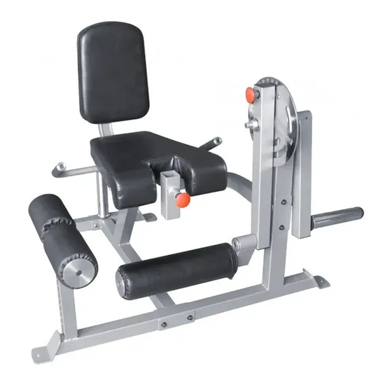
- Page 1 OWNER’S MANUAL F-LEGM Leg Extension & Leg Curl Machine CAUTION! Read all precautions and instructions in this manual before using this equipment.
-
Page 2: Assembly Manual
ESPECIALLY IF YOU ARE OVER THE AGE OF 35 OR HAVE PRE-EXISTING HEALTH PROBLEMS. READ ALL INSTRUCTIONS BEFORE ASSEMBLING OR USING ANY FITNESS EQUIPMENT. FORCE USA FITNESS EQUIPMENT ASSUMES NO RESPONSIBILITY FOR PERSONAL INJURY OR PROPERTY DAMAGE SUSTAINED BY OR THROUGH THE USE OF THIS PRODUCT. SAVE THESE INSTRUCTIONS. -
Page 3: Exploded Diagram
EXPLODED DIAGRAM... -
Page 4: Part List
PART LIST Q’TY Q’TY NUMBER DESCRIPTION NUMBER DESCRIPTION MAIN FRAME FOAM ROLLER FRONT FRAME LONG FOAM ROLLER REAR BASE FOAM COVER BEND SUPPORT LONG FOAM COVER ROTATING SUPPORT FAST PIN WEIGHT POST COTTER PIN LEG HOLDER BUSHING FOAM HOLDER SQUARE PLUG-45 ADJUSTMENT PLATE SQUARE PLUG-50 BACKREST SUPPORT... - Page 5 STEP 01 1. Attach FRONT FRAME (2) and REINFORCEMENT PLATE (17) to MAIN FRAME (1) using two SCREWS M10*75 (44), four WASHERS 10MM (46) and two LOCK NUTS M10 (49). 2. Attach PLATE BAR (14) to REAR BASE (3) using SCREW M10*60 (43). Slide OLYMPIC SLEEVE (15) onto PLATE BAR (14), secure with SCREW M10*25 (42).
- Page 6 STEP 02 1. Attach BEND SUPPORT (4) and WIDE REINFORCEMENT PLATE (18) to MAIN FRAME (1) using two SCREWS M10*75 (44), four WASHERS 10MM (46) and two LOCK NUTS M10 (49). 2. Attach BEND SUPPORT (4) and WIDE REINFORCEMENT PLATE (18) to FRONT FRAME (2) using two SCREWS M10*75 (44), four WASHERS 10MM (46) and two LOCK NUTS M10 (49).
- Page 7 STEP 03 1. Attach LEFT HANDLE BAR (11) and RIGHT HANDLE BAR (12) to rear hole of MAIN FRAME (1) using two SCREWS M10*75 (44), four WASHERS 10MM (46) and two LOCK NUTS M10 (49). 2. Attach SEAT SUPPORT (13) to MAIN FRAME (1) using two SCREWS M10*75 (44), four WASHERS 10MM (46) and two LOCK NUTS M10 (49).
- Page 8 STEP 04 1. Attach BUSHING (32) to FRONT FRAME (2). Insert long axis on ADJUSTMENT PLATE (9) into hole of FRONT FRAME (2). 2. Slide WEIGHT POST (6) onto axis of ADJUSTMENT PLATE (9), insert COTTER PIN (31) into hole on WEIGHT POST (6) and ADJUSTMENT PLATE (9). 3.
- Page 9 STEP 05 1. Attach SEAT CUSHION (22) to SEAT SUPPORT (13) using four SCREWS M8*25 (40) and four WASHERS 8MM (45). 2. Attach BACKREST (23) to BACKREST SUPPORT (10) using two SCREWS M8*25 (40) and two WASHERS 8MM (45). 3. Insert BACKREST SUPPORT (10) into port of MAIN FRAME (1) and secure with FAST PIN (30).
-
Page 11: Warranty
The replacement or repair provided for under the Force USA warranty is the responsibility of the user and the customer will be responsible for any freight charges applicable. Force USA will not be liable for any consequential damages or for breach of any implied warranty on the range of Force USA strength equipment.
Need help?
Do you have a question about the F-LEGM and is the answer not in the manual?
Questions and answers