
Related Manuals for Force F-LATM-B


Summary of Contents for Force F-LATM-B
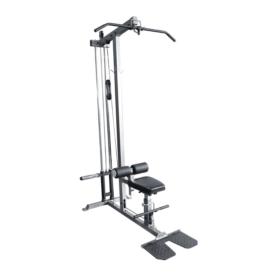
- Page 1 OWNER’S MANUAL F-LATM-B Lat Pulldown Machine CAUTION! Read all precautions and instructions in this manual before using this equipment.
-
Page 2: Assembly Manual
ESPECIALLY IF YOU ARE OVER THE AGE OF 35 OR HAVE PRE-EXISTING HEALTH PROBLEMS. READ ALL INSTRUCTIONS BEFORE ASSEMBLING OR USING ANY FITNESS EQUIPMENT. FORCE USA FITNESS EQUIPMENT ASSUMES NO RESPONSIBILITY FOR PERSONAL INJURY OR PROPERTY DAMAGE SUSTAINED BY OR THROUGH THE USE OF THIS PRODUCT. SAVE THESE INSTRUCTIONS. -
Page 3: Exploded Diagram
EXPLODED DIAGRAM... -
Page 4: Part List
PART LIST Q’TY Q’TY NUMBER DESCRIPTION NUMBER DESCRIPTION LOWER BOOM-UNIT SPRING CLIP LOWER CROSS-FRAME LARGE SPRING CLIP METAL PLATE SHORT CABLE UPRIGHT-UNIT LONG CABLE HARD CHROMIUM SHAFT BUSHING TOP BEAM ROUND PLUG WEIGHT-SLED CARABINER FRONT SUPPORT CHAIN ADJUSTABLE SUPPORT SQUARE PLUG CUSHION SUPPORT RECTANGULAR PLUG LARGE RECTANGULAR... - Page 5 STEP 01 1.Insert hard chromium shaft (5) into hole on lower cross-frame (2), secure with square neck screws M10*60 (46). 2.Attach lower boom-unit (1) and reinforcement plate (19) to lower cross-frame (2) with screws M10*75 (48), washers 10 (51) and lock nuts M10 (52). 3.Attach metal plate (3) to lower boom-unit (1) with connecting shaft (14).
- Page 6 STEP 02 1. Attach upright-unit (4) and front support (8) to lower boom-unit (1) with square neck screws M10*60 (46), washers 10 (51) and lock nuts M10 (52). 2. Attach a pulley (25) and two bushings (32) to upright-unit (4) with screw M10*70 (47), washers 10 (51) and lock nut M10 (52).
- Page 7 STEP 03 1.Attach three pulleys (25) and four bushings (32) to top beam (6) with screws M10*70 (47), screw M10*50 (45), washers 10 (51) and lock nuts M10 (52). 2.Attach hook (13) to top beam (6) with screw M10*75 (48), washers 10 (51) and lock nut M10 (52).
-
Page 9: Warranty
The replacement or repair provided for under the Force USA warranty is the responsibility of the user and the customer will be responsible for any freight charges applicable. Force USA will not be liable for any consequential damages or for breach of any implied warranty on the range of Force USA strength equipment.
Need help?
Do you have a question about the F-LATM-B and is the answer not in the manual?
Questions and answers