Advertisement
Quick Links
NOTE:
Please read all instructions
carefully before using this
product
Table of Contents
Safety Notice
Hardware Identifier
Parts List
Model
JX-1125N
Retain This
Manual for
Reference
2017-2-13
OWNER'S
MANUAL
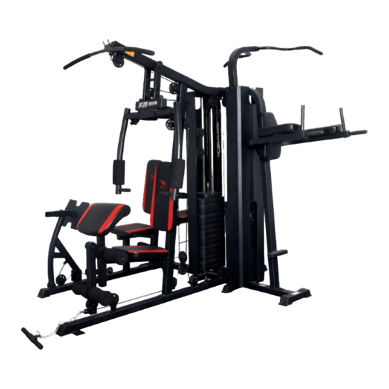
3 Station Home Gym with Leg Press - 148lbs weight
stack for the leg press and 148lbs weight stack for
chest press and leg extension/curl
JX-1125N
Advertisement

Subscribe to Our Youtube Channel
Related Manuals for Force JX-1125N


Summary of Contents for Force JX-1125N
- Page 1 NOTE: Please read all instructions carefully before using this product JX-1125N Table of Contents 3 Station Home Gym with Leg Press - 148lbs weight Safety Notice stack for the leg press and 148lbs weight stack for Hardware Identifier chest press and leg extension/curl...
- Page 2 ORDERING PARTS..................BEFORE YOU BEGIN Thank you for selecting the Five Station Home Gym JX-1125N. For your safety and benefit, read this manual carefully before using the machine. As the distributor, we are committed to provide you complete customer satisfaction.
-
Page 3: Important Safety Precautions
IMPORTANT SAFETY PRECAUTIONS This Gym is built for optimum safety. However, certain precautions apply whenever you operate a piece of exercise equipment. Be sure to read the entire manual before you assemble or use your Gym. In particular, note the following safety precautions: 1. -
Page 4: Hardware Pack
HARDWARE PACK NOTE: The following parts are not drawn to scale. Please use your own ruler to measure the size. - Page 5 HARDWARE PACK NOTE: The following parts are not drawn to scale. Please use your own ruler to measure the size.
- Page 6 HARDWARE PACK NOTE: The following parts are not drawn to scale. Please use your own ruler to measure the size.
- Page 7 HARDWARE PACK NOTE: The following parts are not drawn to scale. Please use your own ruler to measure the size.
-
Page 8: Assembly Instruction
ASSEMBLY INSTRUCTION Tools Required for Assembling the Machine: Two Adjustable Wrenches. NOTE: It is strongly recommended that two or more people assemble this machine to avoid possible injury. Step 1 (See Diagram) A. Insert four Guide Rods (#19) into the holes on the Main Base Frame. Secure each of them with one M10x25mm Allen Bolt (#114) and one Ø10mm Washer (#125) from bottom. - Page 9 Step 2 (See diagram 2) A. Attach Base Frame A (#2) and Base Frame B (#4) to each side of the Main Base Frame (#3), Line up the holes and secure with two M10x90mm Carriage Bolts (#105), two Ø10mm Washers (#125) and M10 Aircraft Nuts (#123).
- Page 10 Step 3(See Diagram 3) A. Attach Front Vertical Support (#7) onto Base Frame A (#2), Line up the holes and secure with two M10x70mm Carriage Bolts (#106), one Bracket (#46), two Ø10mm Washers (#125) and M10 Aircraft Nuts (#123). B. Attach the Up Chinning bar support (#15) onto Base Frame (#4) two M10x70mm Carriage Bolts (#106), one Bracket (#46), two Ø10mm Washers (#125) and M10 Aircraft Nuts (#123) C.
- Page 11 Step 4 (See diagram 4) A. Place Power Tower Main Support (#23) onto the rear side of the Main Support (#3), line up the holes and secure with two M10x70mm Carriage Bolts (#106), one Bracket (#46), two Ø10mm Washers (#125) and M10 Aircraft Nuts (#123) Diagram 4...
- Page 12 Step 5 (See Diagram 5 ) A. Attach Leg Press Support (#31) to the Bracket on the top of the Base Frame C (#28), secure with two M10x16mm Allen bolts (#115), two Bushings (#63) and two Ø10mm Washers (125). B. Attach Foot Leg Press Adjustable Tube (#32) to the bracket on the back of the Foot Plate (#33), secure with one M10x70mm Axle Bolt (#110), two Ø10mm Washers (#125) and M10 Aircraft Nuts (#123).
- Page 13 Step 6 (See diagram 6) A. Slide two sets (each set 14pcs )Weight Stacks (#135) down to Guide Rods (#19) with the slot facing down and out side. Insert the Weight Select Rod (#13) into the center hole of the each set of the Weight Stack (#135).
- Page 14 Step 7 (See diagram 8 and 7) A. Place Left & Right Guide Rod Holder ( #6) onto the top of the Guide Rods (#19), Line up the holes and secure each of them with two M10x25mm Allen Bolts (#114) and Ø10mm Washers (#125). B.
- Page 15 Diagram 8...
- Page 16 Step 8 (See diagram 9 ) A. Attach the Seat Support Frame (#5) to the Front Vertical Support (#7), Line up the holes and secure with two M10x90mm Carriage Bolts (#105), one Bracket (#12), two Ø10mm Washers (#125) and M10 Aircraft Nuts (#123).
- Page 17 Step 9 (See diagram 10) A. Attach Left & Right Dip Arm (#24 & #25) to each side of the Power Tower Main Support (#23), Line up the holes and secure with two M10x90mm Carriage Bolts (#105), two Ø10mm Washers (#125) and M10 Aircraft Nuts (#123).
- Page 18 Step 10 (See diagram 11) A. Attach the Upper Chinning Bar (#8) into the top opening of the Chinning Bar Support Frame (#15), Secure with one M10x85mm Allen Bolt (#108). B. Attach the Main Sit up Support Frame (#26) to the bracket on the back of the Backrest Support Frame (#26), Secure with two M10x16mm Allen Bolts and Ø10mm Washer (#125).
- Page 19 Step 11 (See diagram 12) A. Attach the Butterfly Base Support (#38) to the Upper Frame (#1), line up the hole and secure with Axle (#128), two M10x16mm Allen Bolts and Ø10mm Washers (#125). Place two Ø50x1.5mm End Caps (#85) to each side of the Butterfly Base Support (#38). B.
- Page 20 Step 12 (See diagram 13) A. Attach Left & Right Side Handle (#34 & 35) to each side of the Side Seat Support Frame (#30), Align up the holes and secure with two M10x70mm Allen Bolts (#106), two Ø10mm Washers (#125) and M10 Aircraft Nuts (#123), Place Seat Pad (55) onto the Side Seat Support Frame (#30), Align up the holes and secure with two M8x65mm Allen Bolts (#117) and Ø8mm Washers (#126)。...
- Page 21 Step 13 (See Diagram 14) A. Attach Seat pad to the Seat Pad Support (#5), Align up the holes and secure with two M8x65mm Allen Bolts (#117) and Ø8mm Washers (#126). B. Attach the Arm Curl Pad (#57) to the Arm Pad Stand (#50), Align up the holes and secure with two M8x20mm Allen Bolts (#119) and two Ø8mm Washers (#126).
- Page 22 Step 14 (Diagram 15) A. Attach the Backrest Pad (#52) to the Power Tower Main Support (#23), Secure with two M8x75mm Allen Bolts (#116) and Ø8mm Washers (#126). B. Place two Arm Pads (#53) to Left & Right Dip Arm (#24 & #25), Secure each of them with two M8x65mm Allen Bolts (#117) and Ø8mm Washers (#126).
- Page 23 Step 15 (See diagram 16) A. Slide two Foam Roll Tubes (#22) into the hole on the Seat Support Frame (#5) and Leg Developer (#8) with half way. Attach two Leg Extension Foam Rolls (#96) to each side of the Foam Roll Tubes (#22). Attach four Foam Roll End Caps to each side of the Foam Roll Tubes (#22).
- Page 24 Step 16 (See diagram 17) A. Attach Long Foam Roll Tube (#42) into the hole on the Main Sit up Support Frame (#26) and Short Foam Roll Tube (#43) into the hole on Backrest Support Frame (#29), Attach four Ø22xØ80x160mm Foam Rolls (#98) to each side of the Short &...
- Page 25 Step 17 (See diagram 18) A. Following below diagram and install 51-L1 Cable. 51-L2 Cable, 51-L3 Cable and Ø97mm Pulleys (#99) to the Frame. B. Attach Short Handle Grip (#41) to the Ball end of the 51- L4 Cable with 8 Joint Chain (#101) and two 7# Gourd Hooks (#104).
- Page 26 Step 18 (See diagram 19 and 20) A. Attach the 51-L5 Cable to the Bracket on the Leg Press Support (#31) with one M10x28mm Allen Bolt (#113), two Ø10mm Washers (#125) and one M10 Aircraft Nut (#123). B. Loop the Cable as the Drawing showing in the below diagram 19 and 20. Diagram 19...
- Page 27 Diagram 20...
- Page 28 Diagram 19 (See Diagram 21) A. Attach Left & Right Weight Stack Cage (#20 & # 21) together with four M5x10mm Philips Bolts (#122) and M5 Aircraft Nuts (#124). B. Attach the two weight cage assembling to the Main Base Frame (#3) and secure each of with two M10x16mm Allen Bolts (#115) and two Ø10mm Washers (#125).
- Page 29 PART LIST Key No. Description Key No. Description Upper Frame Lat bar Base Frame A Sleeve Tube Main Base Frame Short Bar Base Frame B Sit Up Board Short Grip Seat Pas Support Frame Sit Up Board Long Grip Left Guide Rod Holder Double Pulley Bracket Front Vertical Support Single Hole Bracket...
- Page 30 Specification Specification Ø95mm Pulley M10×170mm Allen Bolt 6202Z Bearing M10×85mm Allen Bolt 50×45mm Sleeve M10×75mm Allen Bolt Ø45×40mm PP Bumper M10×70mm Allen Bolt Ø25×145mm Handle Grip M10×65mm Axle Bolt Ø25×130mm Handle Grip M10×45 L=15 Axle Bolt Ø25×325mm Handle Grip M10×28mm Allen Bolt Ø26/□50mm Sleeve M10×25mm Allen Bolt 64×44×2.5mm End Cap...
Need help?
Do you have a question about the JX-1125N and is the answer not in the manual?
Questions and answers