
Related Manuals for Force JX-DS925


Summary of Contents for Force JX-DS925
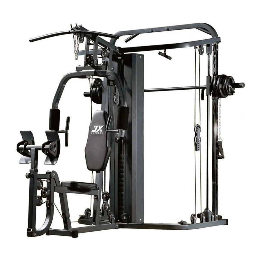
- Page 1 JX-DS925 OWNER’S MANUAL Utility 138lb Home Gym with Leg Press,Smith Machine and Functional Trainer CAUTION! Read all precautions and instructions in this manual before using this equipment.
-
Page 2: Safety Information
35 or persons with pre-existing health problems or those who have not exercised for a period of time. You MUST read all instructions before using any fitness equipment. FORCE USA and its associates assume no responsibility for personal injury or property damage sustained by or through the use of this product. - Page 3 Components - Parts Please check you have all parts listed below Note: Some of the smaller components may be pre-fitted to larger components. Please check carefully before contacting us regarding any missing components.
- Page 5 Components - Fixings Please check you have all parts listed below Note: The quantities below are the correct amount to complete the assembly. In some cases more hardware may be supplied than are required. Some of the fixings are pre-fitted to the larger components. Please check carefully before contacting us regarding any missing fixings.
- Page 6 Assembly Instructions Step 1 Insert 2 pcs guide rods (18#) into the holes of the Rear Stabilizer(4#) separately and secure them with 2 pcs M10*20 Allen Bolt(63#) and 2pcs φ10 washers(69#).Slide the 2pcs rubber bumper(48#) along the guide rods separately. Attach the Base Frame(1#) to the Rear Stabilizer(4#) as the diagram shows and secure them with 2pcs M10*70 carriage bolt(58#),1pc bracket(29#),2pcs φ10 washers(69#) and 2pcs M10 Aircraft nuts(68#) .
- Page 7 Assembly Instructions Step 2 a. Attach the front vertical frame(3#) onto the base frame(1#). Carefully align the holes and secure them with 2pcs M10*70 carriage bolt(58#), 1 pc bracket(37#),2pcs φ10 washers(69#) and 2pcs M10 Aircraft nuts(68#) . b. Attach the left stabilizer(23#) and right stabilizer(24#) to the base frame together ,and secure them with 2pcs M10*70 carriage bolt(58#), 2pcs φ10 washers(69#) and 2pcs M10 Aircraft nuts(68#) .
- Page 8 Assembly Instructions Step 3 Place 13pcs weight plate(44#) along the guide rods(18#) from the top to the bottom, Insert the Selector Rod(13#) into the center hole of the weight plates. And then place the weight stem(45#) again. Select the desired weight with the selector pin(51#) during the exercising.
- Page 9 Assembly Instructions Step 4 Place the Upper Frame(2#) onto the Front Vertical Frame(3#) and 2pcs Guide Rod(18#), Align the holes and secure them with 2pcs M10*20 Allen Bolt (63#),2pcs φ10 washers(69#) ,2pcs M10*70 Carriage bolt(58#),1 pc bracket(37#),2pcs φ10 washers(69#),2pcs M10 Aircraft nuts(68#) .
- Page 10 Assembly Instructions Step 5 Attach the Front Press Frame(6#) to the Upper Frame(2#), Secure them with 1pcs axle(54#),2pcs φ10 washer(69#)and 2pcs M10 Aircraft nut (68#).
- Page 11 Assembly Instructions Step 6 a.Attach the Front support (21#) to the base frame and Secure them with 1 pc M10*70 Carriage bolt(58#),1pcφ10 washer(69#),1pc M10 Aircraft nuts(68#) . b.Attach the one end of seat pad support(5#) to the front vertical frame and secure them with 2pcs M10*70 Carriage bolt(58#),1pc bracket(37#),2pcs φ10 washers(69#),2pcs M10 Aircraft nuts(68#).
- Page 12 Assembly Instructions Step 7 a.Attach the Leg developer (14#) to the bracket of the seat pad support (5#) and Secure them with 1 pc Axle(55#),2pcsφ10 washer(69#),2pcs M10 Aircraft nuts(68#) . b.Attach one end of front connection frame (15#) to the leg developer (14#) and secure them with 1 pc Axle(55#),2pcsφ10 washer(69#),2pcs M10 Aircraft nuts(68#) .
- Page 13 Assembly Instructions Step 8 Attach the Right butterfly(8#) to the front press base (6#) as the diagram shows,Secure them together with 1pc washer (71#),1pc M10 Aircraft nut(68#) . φ25×φ10.5 Push 1pc butterfly foam roll(107#) as the diagram shows.Attach the handle(9#) into the hole of the butterfly and secure it with 1pc M10×20 Allen Bolt (63#), 1pc φ10 washer(69#).
- Page 14 Assembly Instructions Step 9 Attach the left sliding frame(33#) through the rear vertical frame(32#), and attach the rear vertical frame (32#) to the left stabilizer(23#),Secure them together with 2pcs M10*20 Allen bolt(63#) and 2 pcsφ10 washer(69#). Move the sliding frame and Select the desired height with the T shape lock pin(47#). Repeat the same way to install the another one.
- Page 15 Assembly Instructions Step 10 Slide the moving frame (17#) through the short guide rod(19#),attach the short guide rod (19#) into the hole of the safety hook (116#),and attach the safety hook (116#) to the hole of the rear vertical frame(32#). Repeat the same way to install another one.
- Page 16 Assembly Instructions Step 11 Attach the left & right upper fame (25#,26#) to the upper fame (2#)and secure them together with 2pcs M10X70 Carriage bolt (58#) ,2 pcsφ10 washer(69#) and 2pcs M10 Aircraft nuts(68#) . Place the left & right upper fame (25#,26#) onto the short guide rod(19#) and rear vertical frame(32#) separately.
- Page 17 Assembly Instructions Step 12 Attach the big bracket(35#) to the right sliding frame(34#) and secure them with 1pc M12X90 Allen bolt(57#),2pcs φ12 washer (67#) and 1 pc M12 aircraft nut(66#). Repeat the same way to install the another one.
- Page 18 Assembly Instructions Step 13 Attach the barbell bar(27#) through the hole of the moving frame (17#) , hollow tube(30#),and moving frame(17#),Tighten the 2pcs M10*16 Allen bolt (64#)separately. Attach the 2pcs olympic sleeves(102#) to the both end of the barbell separately and tighten the M6*10 sunk bolt with the 4# Allen bolt wrench separately.
- Page 19 Assembly Instructions...
- Page 20 Step 14 Important: Study and follow the diagram carefully. A Attach the 2950 mm Upper cable (86#) through the opening of the upper frame (2#). Place 1PC Pulley (103#) below the cable and secure the 1st pulley using 1PC M10 × 45 Allen bolt (61#) ,2PC ø10 washer (69#) and 1×M10 Aircraft nut (68#).
- Page 21 Assembly Instructions Step 15 Important: Study and follow the diagram carefully. A Attach the end of the 3020 MM butterfly cable(82#) to the hook . B. place 1X pulley (103#) below the cable , Secure the pulley to the swivel pulley bracket(12#) with 1PC M10X45 Allen bolt (61#),2pcs φ10 washer (69#) and 1pcM10 Aircraft nut (68#).
- Page 22 Assembly Instructions...
- Page 23 Step 16 A Attach the end of the 3980 mm leg press cable(84#) to the bracket and secure it with 1PC M10X28 Allen bolt (62#),2pcs φ10 washer (69#) and 1pcM10 Aircraft nut (68#). B. Place 1 pulley(103#) below the cable and secure the pulley to the bracket as the diagram shows with 1PC M10X45 Allen bolt (61#),2pcs φ10 washer (69#) and 1pcM10 Aircraft nut (68#).
- Page 24 Assembly Instructions...
- Page 25 Step 17 A Attach the end of the 4020MM lower cable(85#) to the hook as the diagram shows. B Draw the cable downwards and place 1pc pulley onto the cable, secure it with double floating pulley bracket(36#) together with 1PC M10X45 Allen bolt (61#),2pcs φ10 washer (69#) and 1pcM10 Aircraft nut (68#).
- Page 26 Assembly Instructions Step 18 Repeat the same way in Step 17 to install the step 18.
- Page 27 Assembly Instructions...
- Page 28 Step 19 A. Attach the end of the 7900MM adjustment cable (83#) to the left sliding frame(33#) as the diagram shows. B. Draw the cable downwards and place 1pc pulley onto the cable,Secure it with 1PC M10X45 Allen bolt (61#),2pcs φ10 washer (69#) and 1pcM10 Aircraft nut (68#). C.Draw the cable around the cable and backwards, Place 1pc pulley onto the cable, Secure it with the same way in B.
- Page 29 Assembly Instructions Step 20 Attach the 2pcs weight stack cover(31#) as the diagram shows and secure them with 4pcs M10X20 Allen bolt(63#) and 4pcsφ10 washer (69#)
- Page 30 Assembly Instructions Step 21 A. Place the seat pad(40#) to the seat pad support (5#) and secure it with 4pcs M8×18 Allen bolt (65#) and 4pcs φ8 washer(70#). B. Attach the backrest pad(41#) to the front vertical frame(3#), Secure it with the same way in A. C.Install the shoulder pad as the diagram shows...
- Page 31 Assembly Instructions Step 22 Attach the lat bar(22#) to the end of upper cable with 2pcs 7# Gourd hook(49#) and 15 joint chain(52#).
- Page 32 Assembly Instructions Step 23 A Attach the 2pcs single strap(42#) to the two ends of the lower cable separately with 4pcs 7# Gourd hook(49#) and 2pcs 15-Joint Chain(52#). B. Attach the handle(38#), Tricep rope(104#) and V shape handle(20#) to the hook with the 7#gourd hook separately.
- Page 33 Workout Area The free area must be at least 0.6m greater than the training area. This is a space where you can safely dismount, without obstruction, in case of an emergency. Where two pieces of equipment are positioned adjacent to each other the free area may be shared. Only two person should be within the training area when the equipment is in use.
- Page 34 Exercise Information Before starting Tailor your exercise program according to your physical condition. If you have been inactive for several years, or are overweight, you must start slowly and increase your time on the equipment; a few minutes per workout increase is advisable. Initially, you may be able to exercise only for a few minutes in your target zone, however, your aerobic fitness will improve over the next six to eight weeks.
- Page 35 Exercise Information Muscle Chart Aerobic Exercise Aerobic exercise improves the fitness of your lungs and heart - your body’s most important muscle. Aerobic exercise is promoted by any activity that uses your large muscles (arms, legs, or buttock, for example). Weight Training Along with aerobic exercising which helps get rid of and keep off the excess fat that our bodies can store, weight training is an essential part of an exercise routine.
- Page 36 Exercise Information Warming up and Cooling down Each workout should include the following three parts: 1. A warm-up, consisting of 5 to 10 minutes of stretching and light exercise. A proper warm-up increases your body temperature, heart rate, and circulation in preparation for exercise. 2.
- Page 37 Exercise Information Calf/Achilles stretch With one leg in front of the other, reach forward and place your hands against a wall. Keep your back leg straight and your back foot flat on the floor. Bend your front leg, lean forward and move your hips toward the wall.
- Page 38 Exercise Information Using the Home Gym Important: When working out, do the following for each exercise: exhale while exerting/lifting and inhale while returning to starting position in a slow and controlled manner. Read all caution and warning stickers before using this equipment. ...
-
Page 39: Care And Maintenance
Care and Maintenance Replace defective The safety level of the Do not attempt to repair components immediately equipment can only be this equipment yourself. and/or keep the equipment out maintained if it is examined Should you have any difficulty of use until repair. regularly for damage and wear with assembly, operation or Pay special attention to... -
Page 40: Parts List
Parts List Part # Description QTY Part # Description Base Frame φ53×M18×φ10 Lock knob Upper Frame M18×1.5×φ12 Tshape Lock nob Front vertical frame Rubber bumper Rear Stabilizer 7# Gourd hook Seat Pad support Spring collar Front press base Selector pin Left butterfly 15-joint Chain Right butterfly... - Page 41 Part # Description QTY Part # Description φ32×2.0 End cap □50×2.0 End cap □45×1.5 End cap □45×2.0 End cap □50×1.5 End cap φ45×2.0 End cap φ25×2.5 End cap □50 foot □50×□45 sleeve □60×2.0×□45×60 sleeve φ38×φ27×26 bushing φ50×φ26.5×300 olympic sleeve φ97 pulley Tricep pull rope Small rubber bumper 48×48×5×φ10.5 rubber bumper...
Need help?
Do you have a question about the JX-DS925 and is the answer not in the manual?
Questions and answers