Hunter Stoves Herald 80B CE V.II Installation And Operating Instructions Manual
Hide thumbs
Also See for Herald 80B CE V.II:
Advertisement
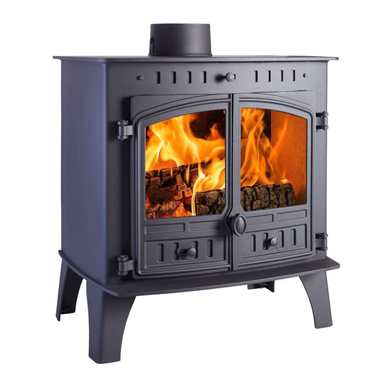
H E R A L D
C E N T R A L - H E A T I N G
Installation and Operating Instructions
WARNING: Improper installation, adjustment, alteration, service or maintenance can cause
injury or property damage. For assistance or additional information consult an authorized
technician, or your Hunter Dealer.
FOR YOUR SAFETY: Do not store or use gasoline or other flammable vapours and liquids
in the vicinity off this appliance. Installation and service must be performed by authorized
personnel.
PLEASE KEEP THESE INSTRUCTIONS FOR FURTHER REFERENCE.
Manufactured in United Kingdom by:
Hunter Stoves Limited
Aspen House
Pynes Hill
Exeter
Devon, EX2 5AZ
E Mail:
info@hunterstoves.co.nz
Web:
www.Hunterstoves.co.uk
Herald 80B 07102013
C E
M U L T I F U E L
S T O V E
Tested to AS/NZS 2918:2001
Test report 12/2569
8 0 B
V . I I
Distributed in New Zealand by:
Classic Cookers
151 Bramleys Road
R D 1
Kaiapoi
Ph. 03 3106534
Email: info@classiccookers.co.nz
Web: www.classiccookers.co.nz
Page 1
Advertisement

Related Manuals for Hunter Stoves Herald 80B CE V.II


Summary of Contents for Hunter Stoves Herald 80B CE V.II
- Page 1 Installation and service must be performed by authorized personnel. PLEASE KEEP THESE INSTRUCTIONS FOR FURTHER REFERENCE. Manufactured in United Kingdom by: Distributed in New Zealand by: Hunter Stoves Limited Classic Cookers Aspen House 151 Bramleys Road Pynes Hill...
-
Page 2: Table Of Contents
Contents Page No Technical Specifications Page 3 Assembly Instructions Page 4 Installation Instructions Page 5-13 Operating Instructions Page 14-17 General Maintenance Page 18-19 Stove Spares Page 20-21 Herald 80B 07102013 Page 2... -
Page 3: Technical Specification
Herald 80B CE V.II Central-Heating Technical Specification Stove Mass 218 kg Wood Total Efficiency 71.0% Nominal Heat Output 21.5 KW Output to Water 12.4 KW Output to Room 9.1 KW Mean CO Emission (at 13% O2) 0.38 % Mean Flue Gas Temperature 368 °C... -
Page 4: Assembly Instructions
Assembly Instructions PLEASE READ THESE INSTRUCTIONS CAREFULLY It is important that your stove is correctly installed, as Hunter Stoves Limited cannot accept responsibility for any fault arising through incorrect use or installation. Important Warning This stove must not be installed into a chimney that serves any other heating appliance. -
Page 5: Installation Instructions
Installation Instructions These instructions cover the basic principles to ensure satisfactory installation of the stove, although detail may need slight modification to suit particular local site conditions. In all cases the installation must comply with current Building Regulations, Local Authority Byelaws, national standards and other specifications or regulations as they affect the installation of the stove. - Page 6 80B Dimensions (in millimetres) Herald 80B 07102013 Page 6...
- Page 7 Installation Installing the Flue You MUST use a flue system, which complies with the current installation Standard AS/NZS 2918. Full instructions are supplied with the flue kit, and these MUST be followed closely, including the minimum flue exit height from the top of the floor protector and the minimum exit height above the roofline or roof ridge as detailed in the instructions.
- Page 8 Material Clearance Corner Orientation Where the sides of the stove are at 45 degrees to the walls Rear corner of the stove to combustibles is 195mm 195mm from corner of 195mm from corner top hot plate to of top hot plate to combustibles combustibles 90mm of concrete or...
- Page 9 Material Clearances 170 mm from 250mm from top top hot plate to hot plate to combustibles combustibles Note: walls are combustible and all dimensions stated are minimum 300mm 90mm of concrete or specified hearth FLOOR PROTECTOR (Hearth) REQUIREMENTS — Freestanding models Unless your wood fire will be standing on an un-covered fireproof floor 90mm of concrete (containing no combustible material) extending at least 500mm from the appliance, it will be necessary to provide a floor protector (hearth).
- Page 10 Hearth Size The minimum size hearth for a Herald 80B is 950mm wide with the stove sitting central on the hearth. The minimum measurement from the front of the hearth to the back of the stove’s bottom plate is 780mm This measurement gives the minimum hearth requirement of 300mm Total length of the hearth when no wall shielding is used is 1030mm Herald 80B 07102013...
- Page 11 We strongly recommend that a knowledgeable, experienced and qualified plumbing and heating engineer is responsible for the design and installation of the heating and hot water system. Hunter Stoves Ltd cannot accept responsibility for any consequential loss, however caused, due to under or over specification of the appliance in any installation.
- Page 12 Systems using a common flow and return to the boiler should incorporate an injector tee on the primary return connection from the central heating pump (see diagram). A HIGH LIMIT thermostat should be fitted to the gravity flow pipe close to the boiler and set at 90°C. This should override any pump control, switching the pump on and dissipating any excess heat around the radiator circuit.
- Page 13 Wiring Diagram for general guidance only All electrical work must be carried out by a competent electrician in accordance with the rules in force and the instructions provided by the circulating pump and heating controls manufacturer Commissioning and Handover Upon completion of the installation, allow a suitable period of time for any fire cement and mortar to dry out.
-
Page 14: Operating Instructions
Operating Instructions This appliance is not suitable for use in a shared flue This appliance should not be operated with the doors open Aerosol Sprays Do not use an aerosol spray on or near the stove when it is alight. Air Controls This stove has been designed to burn cleaner and more efficiently than a conventional wood burning stove. - Page 15 Multifuel Grate Your Hunter Stove is fitted with a locomotive type grate. So that de- ashing can be carried out cleanly and easily, it is riddled from the outside of the stove with the doors closed. The grate is designed to burn both wood and solid fuels.
- Page 16 Notes on Wood burning With a full load of wood, the stove will need to be refuelled approximately once every 1.5 hours. Wood can be stacked higher in the stove than solid mineral fuel but care must be taken that logs do not touch or move the baffle.
-
Page 17: Safety Notes For Your Guidance
Safety notes for your guidance FIRES CAN BE DANGEROUS – Always use a fireguard in the presence of children, the elderly or the infirm. DO NOT OVERFIRE – it is possible to fire the stove beyond its design capacity, this could damage the stove, so watch for signs of overfiring –... -
Page 18: General Maintenance
Rope Check the rope around the door and glass. If rope is becoming detached, use Hunter Stoves rope glue to reattach it. If the rope is in a poor condition, a replacement rope kit may be ordered from the Hunter Stoves spares range. - Page 19 Chimney and Flue ways It is important that the chimney, flue ways and any connecting flue pipe are swept regularly. This means at least once a year for smokeless fuels and at least twice a year for wood and other fuels. The baffle will need to be removed from its supports in order to sweep the chimney (see assembly instructions).
-
Page 20: Stove Spares
STOVE SPARES Only Hunter Stoves authorised spares should be used with this appliance RIGHT HAND DOOR Right Hand Door (HHR16/002) Door Glass (HHR16/005) Glass Clip (HHR08/046) Glass Gasket Glass Clip Screw (FSJM05008SS) (HHR16/006) Door Slider (HHR22/042) Slider Knob (HHR08/045) LEFT HAND DOOR... - Page 21 STOVE BODY ASSEMBLY – PART SECTION - MULTIFUEL Flue Collar (HHR16/010) Top Air Slider (HHR16/043) Slider Knob Flue Cover (HHR08/045) (HHR16/011) Baffle (HHR22/034) Side Plates (HHR18/008 A/B) Riddling Support (HHR20/024) Catch Bar Primary Air Deflector (HHR16/004) Multifuel (HHR22/024) Ashpan Riddling Bar – Lower (HHR16/044) (HHR16/024) Riddling Bar –...
Need help?
Do you have a question about the Herald 80B CE V.II and is the answer not in the manual?
Questions and answers