Table of Contents
Advertisement
Advertisement
Table of Contents

Related Manuals for Acer AcerPower Flex4000 Series


Summary of Contents for Acer AcerPower Flex4000 Series
- Page 1 AcerPower User’s Guide Flex4000 Series (V59LA/IDB3-C) Index...
- Page 2 Acer and its suppliers make no representations or warranties, either expressed or implied, with respect to the contents hereof and specifically disclaim any warranties of merchantability or fitness for a particular purpose. Further, Acer reserves the right to revise this publication and to make changes from time to time in the contents hereof without obligation to notify any person of such revisions or changes.
- Page 3 (e) sublicense or otherwise make the software available to third parties. The software is the property of Acer or Acer’s supplier and you do not have and shall not gain any proprietary interest in the software (including any modifications or copies made by or for you) or any related intellectual property rights.
-
Page 4: Important Safety Instructions
Never spill liquid of any kind on the product. 12. Do not attempt to service this product yourself, as opening or removing covers may expose you to dangerous voltage points or other risks. Refer all servicing to qualified service personnel. AcerPower Flex4000 Series (V59LA/IDB3-C) User’s Guide... - Page 5 13. Unplug this product from the wall outlet and refer servicing to qualified service personnel under the following conditions: When the power cord or plug is damaged or frayed b. If liquid has been spilled into the product If the product has been exposed to rain or water d.
- Page 6 The changes or modifications not expressly approved by the party responsible for compliance could void the user's authority to operate the equipment. Notice 2: Shielded interface cables, if any, must be used in order to comply with the emission limits. AcerPower Flex4000 Series (V59LA/IDB3-C) User’s Guide...
- Page 7 Conventions The following are the conventions used in this manual: , etc. Represent the actual keys that you have to press on the keyboard. NOTE Gives bits and pieces of additional information related to the current topic. WARNING Alerts you to any damage that might result from performing or not performing specific actions.
-
Page 8: Table Of Contents
1.7 Video Function................... 1-19 1.7.1 Supported Video Resolutions ............1-20 1.8 Audio Function................... 1-21 1.9 Error Messages................... 1-21 1.9.1 Software Error Messages ..............1-22 1.9.2 System Error Messages..............1-22 1.9.3 Correcting Error Conditions ............1-25 AcerPower Flex4000 Series (V59LA/IDB3-C) User’s Guide... - Page 9 Chapter 2 BIOS Utility 2.1 Entering Setup....................2-1 2.2 System Information ..................2-3 2.2.1 Processor ................... 2-4 2.2.2 Processor Speed................. 2-4 2.2.3 Internal Cache ................... 2-4 2.2.4 External Cache .................. 2-5 2.2.5 Floppy Drive A.................. 2-5 2.2.6 Floppy Drive B .................. 2-5 2.2.7 IDE Primary Channel Master ............
- Page 10 3.6.6 Installing a System Board ..............3-15 3.6.7 Installing the Power Supply ............. 3-17 3.6.8 Installing Expansion Boards ............3-18 3.6.9 Installing the Cover ................. 3-20 Chapter 4 Acer Manageability Software 4.1 The Acer Resource CD ................. 4-2 AcerPower Flex4000 Series (V59LA/IDB3-C) User’s Guide...
- Page 11 4.2 Acer Software Installer ................. 4-4 4.3 Acer Software Library .................. 4-5 4.4 Acer Online Documentation ................. 4-6 4.5 Using Acer CPR to Rebuild Your Hard Drive ..........4-6 ® ® 4.6 McAfee VirusScan ..................4-9 4.6.1 Installing VirusScan ..............4-10 4.6.2...
- Page 12 B.3.3 Memory at 15MB-16MB Reserved For ..........B-7 B.3.4 Memory Parity Mode .................B-7 B.3.5 C8000h – DFFFFh Shadow ...............B-8 B.3.6 Onboard Peripheral Configuration.............B-8 B.3.7 PnP/PCI System Configuration ............B-13 B.4 Power Management ..................B-16 B.4.1 ACPI BIOS..................B-17 B.5 Exit Setup Utility..................B-17 Index AcerPower Flex4000 Series (V59LA/IDB3-C) User’s Guide...
- Page 13 Installing a CPU ..................1-14 Attaching the Heatsink and Fan to the CPU ..........1-14 Installing a DIMM .................. 1-17 Removing a DIMM ................. 1-18 Acer Resource CD..................4-2 Acer Software Installer................4-4 Front Panel ....................A-4 Rear Panel ....................A-5 List of Tables Chip Select Frequency................
- Page 14 Introduction Acer is on the leading edge of microcomputer systems development for both corporate and home computing needs, as the OEM of choice for many of the world’s leading computer companies. Acer is committed to meeting the world’s demand for state-of-the-art computers ...
-
Page 15: About This Manual
About this Manual This manual is divided into four chapters. A brief description of these chapters is provided below. Chapter 1 System Board Describes the system board and all its major components. It contains information about the system board layout, jumper and connector locations and functions, jumper settings, and memory configuration. - Page 16 Intel LANDesk Client Manager. The Acer Resource CD contains the Acer CPR utility, the Acer Software Installer, the Acer software library and Acer online documentation. Use Acer CPR to restore your computer to its original factory settings. Use the Acer Software Installer to install the bundled software that resides on the Acer Resource CD.
-
Page 17: Chapter 1 System Board
System Board ® The all-in-one Pentium -based system board features the common functions offered by a high-performance board, as well as multimedia functions. It supports Pentium processors with or without MMX™ technology. It has slots on a riser card for future expansion. Two 168-pin DIMM sockets can accommodate 16, 32, 64, and 128 MB memory modules for a maximum memory upgrade of 256 MB. -
Page 18: System Board Layout
One 9-pin UART 16C550 compatible serial port and one SPP/ECP/EPP parallel port • Two USB ports • PS/2 mouse and keyboard ports • Plug-and-Play (PnP) functionality • Power-management functionality • Software shutdown • Hardware Monitoring function that supports CPU thermal, voltage, and fan stop indicators AcerPower Flex4000 Series (V59LA/IDB3-C) User’s Guide... -
Page 19: System Board Layout
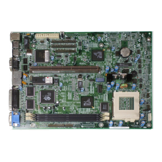
Figure 1-1 shows the board layout and the locations of the important components. 13 14 9 10 5-pin Fan connector RJ45 port (for Hardware Monitoring) PS/2 keyboard port 2-pin Fan connector PS/2 mouse port Power, LED connector COM1 port Voltage regulator with heatsink USB ports Game port Parallel port... -
Page 20: Jumpers And Connectors
Jumpers and Connectors Figure 1-2 shows the jumper and connector locations on the system board. Figure 1-2 Jumper and Connector Locations The shaded pin indicates pin 1. AcerPower Flex4000 Series (V59LA/IDB3-C) User’s Guide... -
Page 21: Chip Select Frequency
The following tables list the jumper settings and their corresponding functions: Table 1-1 Chip Select Frequency JP18 JP19 JP20 66 (default) 83.3 Table 1-2 SW1 Bus Frequency Selection Bus Freq. 60 MHz 66 MHz (default) 75 MHz 83.3 MHz Table 1-3 SW1 CPU Frequency for Pentium CPUs P54C P55C... -
Page 22: System Board Jumper Settings
Video Interrupt 2-3* Disable 3.52V H/W Monitoring 2-3* 3.3V 1-2* 2.8V H/W Monitoring 2.9V 3.2V 2.1V 9-10 1.8V Disable 2-3* Enable JP4 on the motherboard is incorrect. Table 1-4 above has correct information. Default Setting AcerPower Flex4000 Series (V59LA/IDB3-C) User’s Guide... - Page 23 Support Reset Switch JP13 1-2 * Disable Boot Block Enable JP14 Short* P55C Open P54C JP15 1-2* Enable Disable JP16 1-2* No UPS JP17 LED connection LAN Connector JP21 Acer Logo Reserved JP22 Check Password 2-3* Bypass Default setting Index...
-
Page 24: Onboard Connectors
CN14 Wake-on LAN connector CN15 Voltage select connector CN16 Ring-In wake up connector (Not Used) CN17 Front Panel Joystick CN18 COM1 connector CN19 PS/2 Mouse CN20 Floppy disk connector CN21 IDE channel 1 connector AcerPower Flex4000 Series (V59LA/IDB3-C) User’s Guide... -
Page 25: Cn15 Voltage Connector
Table 1-5 Onboard Connectors (continued) Connector Function CN22 PS/2 Keyboard CN23 IDE channel 2 connector CN24 LAN LED (Not Used) CN25 RJ45 (LAN Jack) CN26 Power connector CN27 Audio I/O connector CN28 Standby connector (from power supply) CN29 Fax/Modem connector (Not Used) CN31 IRDA connector (Not Used) CDIN1... -
Page 26: Led/Switch Locations
1.2.1 LED/Switch Locations The figure below shows the pin assignments and orientation for each of the front panel connectors and the LED. AcerPower Flex4000 Series (V59LA/IDB3-C) User’s Guide... -
Page 27: Installing Components On The System Board
Installing Components on the System Board The following sections describe how to install components on the system board, including how to install a Pentium processor and how to upgrade system memory. Before beginning the installation, please take a moment to read the sections below. They contain important ESD precautions and pre- and post-installation instructions. -
Page 28: Pre-Installation Instructions
2. Make sure you have set all the required jumpers. See section 1.2 for the correct jumper settings. 3. Replace any expansion boards or peripherals that you removed earlier. 4. Replace the system cover. 5. Connect the necessary cables and turn on the system. AcerPower Flex4000 Series (V59LA/IDB3-C) User’s Guide... -
Page 29: Installing A Cpu
Installing a CPU 1.4.1 Installation Procedures Observe the ESD precautions when installing components. See section 1.3.1. Notched corner The system board features a zero-insertion force (ZIF) socket for easy CPU installation. Follow these steps to install a CPU: 1. Pull up the socket lever. 2. -
Page 30: Installing Memory
DIMM modules with or without ECC functions. The ECC function enables the system to automatically detect and correct data errors. Table 1-7 lists the possible memory configurations. Table 1-7 Memory Configurations DIMM 1 DIMM 2 Total Memory AcerPower Flex4000 Series (V59LA/IDB3-C) User’s Guide... - Page 31 Table 1-7 Memory Configurations DIMM 1 DIMM 2 Total Memory 8 MB 16 MB 16 MB 24 MB 32 MB 40 MB 64 MB 72 MB 128 MB 136 MB 16 MB 16 MB 16 MB 24 MB 16 MB 16 MB 32 MB 16 MB...
- Page 32 192 MB 128 MB 128 MB 128 MB 136 MB 128 MB 16 MB 144 MB 128 MB 32 MB 160 MB 128 MB 64 MB 192 MB 128 MB 128 MB 256 MB AcerPower Flex4000 Series (V59LA/IDB3-C) User’s Guide...
-
Page 33: Installing A Dimm
1.5.1 Installing a DIMM Follow these steps to install a DIMM: 1. Align pin 1 of the DIMM with pin 1 of the socket. Pin 1 is labeled 1 on both the DIMM and the socket. 2. Gently push the DIMM until the holding clips lock the DIMM into a vertical position. Figure 1-5 Installing a DIMM Be careful when inserting DIMMs. -
Page 34: Removing A Dimm
2. Gently pull the DIMM out of the socket. Figure 1-6 Removing a DIMM 1.5.3 Reconfiguring the System The system automatically detects the amount of memory installed. Run Setup (see section 2.1) to view the new value for total system memory. AcerPower Flex4000 Series (V59LA/IDB3-C) User’s Guide... -
Page 35: Second-Level Cache
Second-level Cache The board comes with 512-KB pipelined-burst SRAM level 2 cache. Refer to the following table for the cache configuration. Table 1-8 Second-level Cache Configuration Cache Data RAM Location Tag RAM Cacheable Size (9 ns) (15 ns - U39) Memory 512 KB 64K x 64 x 1 pcs... -
Page 36: Supported Video Resolutions
46.9 49.5 800 x 600 57.1 56.6 800 x 600 62.5 67.5 1024 x 768 35.5 44.9 43 int. 1024 x 768 48.3 65.0 1024 x 768 56.4 75.0 1024 x 768 58.2 75.0 AcerPower Flex4000 Series (V59LA/IDB3-C) User’s Guide... -
Page 37: Audio Function
Table 1-9 Video Resolutions (continued) Display Refresh Horizontal Pixel Clock Resolution Rate Frequency (KHz) (MHz) 1024 x 768 60.0 78.8 1024 x 768 76.2 1024 x 768 79.0 1152 x 864 45.8 65.0 43 int. 1152 x 864 44.9 65.0 47 int. -
Page 38: Software Error Messages
A system error message indicates a problem with the computer itself. These messages normally appear during the Power-On Self-Test (POST), before the operating system prompt appears. Table 1-10 lists the system error messages in alphabetical order. AcerPower Flex4000 Series (V59LA/IDB3-C) User’s Guide... - Page 39 Table 1-10 System Error Messages Error Message Corrective Action Bad CMOS Battery Replace battery. Contact your dealer. CMOS Checksum Run Setup (see section 2.1). Error Diskette Drive Check and connect the cable to the Controller Error diskette drive or controller. Diskette Drive Error Diskette may be bad.
- Page 40 Ctrl-Alt- Esc for Setup Press Esc to turn off Press to disregard NMI error. Press NMI, any key to any key to reboot the system. reboot Protected Mode Test Contact your dealer. Fail AcerPower Flex4000 Series (V59LA/IDB3-C) User’s Guide...
-
Page 41: Correcting Error Conditions
Table 1-10 System Error Messages (continued) Error Message Corrective Action RAM BIOS Error Contact your dealer. Real Time Clock Run Setup (see section 2.1). Error Shadow RAM Fail Contact your dealer. System Memory Check DIMMs on system board or Address Error contact your dealer. - Page 42 If you are sure that your configuration values are correct and your battery is in good condition, the problem may lie in a damaged or defective chip. Contact an authorized service center for assistance. AcerPower Flex4000 Series (V59LA/IDB3-C) User’s Guide...
-
Page 43: Chapter 2 Bios Utility
BIOS Utility Most systems are already configured by the manufacturer or dealer. There is no need to run Setup when starting the computer unless you get a Run Setup message. The Setup program loads configuration values into the battery-backed nonvolatile memory called CMOS RAM. - Page 44 You must press while the system is booting. This key combination does not work during any other time. AcerPower Flex4000 Series (V59LA/IDB3-C) User’s Guide...
-
Page 45: System Information
The BIOS Utility Main Menu appears: BIOS Utility System Information Basic Configuration System Security Power Management Exit Setup Utility ↵ ↑↓←→ = Move highlight bar, = Select, Esc = Exit The Main Menu screen displays the basic configuration level. This level of configuration allows you to change the basic parameters of your system as in the following: •... - Page 46 The command line at the bottom of the menu tells you how to move from one screen to another and return to the Main menu. Press to move to the next page or to return to the previous page. Press to return to the Main menu. AcerPower Flex4000 Series (V59LA/IDB3-C) User’s Guide...
-
Page 47: Processor
The following screen shows page 2 of the System Information menu. System Information Page 2/2 Serial Port 1 ..... 3F8h, IRQ 4 Serial Port 2 ..... Disabled Parallel Port ....378h, IRQ 7 PS/2 Mouse ......Installed Memory Parity Mode ....Disabled USB Host Controller .... -
Page 48: External Cache
IDE Secondary Channel Master This parameter specifies the current configuration of the IDE device connected to the master port of the secondary IDE channel. For information on how to configure the IDE drives, see section 2.3.4. AcerPower Flex4000 Series (V59LA/IDB3-C) User’s Guide... -
Page 49: Ide Secondary Channel Slave
2.2.10 IDE Secondary Channel Slave This parameter specifies the current configuration of the IDE device connected to the slave port of the secondary IDE channel. For information on how to configure the IDE drives, see section 2.3.4. 2.2.11 Total Memory This parameter specifies the total amount of onboard memory. -
Page 50: Ps/2 Mouse
RAM, and replacing it with parity or ECC RAM. You cannot mix ECC and non-ECC RAM together. 2.2.17 USB Host Controller This parameter specifies whether the onboard USB controller is enabled or disabled. AcerPower Flex4000 Series (V59LA/IDB3-C) User’s Guide... -
Page 51: Product Information
2.2.18 Product Information The Product Information contains the general data about the system, such as the product name, serial number, BIOS version, etc. This information is necessary for troubleshooting (may be required when asking for technical support). The following figure shows how the Product Information screen appears. Product Information Page 1/1 Product Name ...... -
Page 52: Basic System Configuration
As long as the internal battery remains good (approximately seven years) and connected, the clock continues to keep the date and time accurately even when the power is off. AcerPower Flex4000 Series (V59LA/IDB3-C) User’s Guide... - Page 53 Date Highlight the items on the Date parameter and press to set the date following the month-day-year format. Valid values for month, day, and year are: • Day of the Week (Sun-Sat) • Month • • 1980 2099 Year Time Highlight the items on the Time parameter and press to set the time following the hour-minute-second format.
-
Page 54: Diskette Drives
[360 KB, 5.25-inch] • [1.2 MB, 5.25-inch] • [720 KB, 3.5-inch] • [1.44 MB, 3.5-inch] Follow the same procedure to configure floppy drive B. Choose None if you do not have a second floppy drive. AcerPower Flex4000 Series (V59LA/IDB3-C) User’s Guide... -
Page 55: Drive (Non-Standard Feature)
2.3.3 LS-120 Drive (Non-Standard Feature) This parameter allows you not only to enable an LS-120 device if installed in your system, but specify the function of the device. The setting affects how the BIOS will detect the device. Possible settings are: •... -
Page 56: Ide Drives
This parameter lets you configure the hard disk drive connected to the master port of the secondary IDE channel. IDE Secondary Channel Slave This parameter lets you configure the hard disk drive connected to the slave port of the secondary IDE channel. AcerPower Flex4000 Series (V59LA/IDB3-C) User’s Guide... - Page 57 The following screen appears if you select any of the IDE Drive parameters: IDE Primary/Secondary Channel Master/Slave Page 1/1 Type ......[ Auto ] Cylinder ..... [ XXXX ] Head ......[ XXXX ] Sector ....... [ XXXX ] Size ......[ XXXX ] MB Hard Disk Size >...
-
Page 58: Enhanced Ide Features
504 MB. This is made possible through the Logical Block Address (LBA) mode translation. However, this enhanced IDE feature works only under DOS and Windows environments. Other operating systems require this parameter to be set to Disabled AcerPower Flex4000 Series (V59LA/IDB3-C) User’s Guide... -
Page 59: Boot Options
2.3.5 Boot Options This option allows you to specify your preferred setting for bootup. The following screen appears if you select Boot Options from the Basic Configuration menu: Boot Options Page 1/1 Fast Boot ......[Disabled] Silent Boot ......[Disabled] Num Lock After Boot ....[Enabled ] Memory Test ......[Disabled] Boot from LanDesk Service Agent ..[Disabled] Boot Sequence... -
Page 60: Num Lock After Boot
The system then check this drive if it can not boot from the specified drive. • search failed then boot from this drive. The BIOS will display an error message if the drive(s) specified is not bootable. AcerPower Flex4000 Series (V59LA/IDB3-C) User’s Guide... -
Page 61: Boot From Landesk Service Agent
Boot from LANDesk Service Agent When set to Enabled , the system boots from a LANDesk Service Agent network instead of your desktop system. The LANDesk Service Agent is IEEE-standards-based code that intervenes in the boot process. To be able to use this option, your system administrator must prepare a network server with appropriate software in advance. -
Page 62: System Security
The disk drive control features allow you to control the floppy drive or the hard disk drive boot function to prevent loading operating systems or other programs from a certain drive while the other drives are operational. Table 2-1 lists the drive control settings and their corresponding functions. AcerPower Flex4000 Series (V59LA/IDB3-C) User’s Guide... -
Page 63: Setup Password
Table 2-1 Drive Control Settings Floppy Drive Setting Description Normal Floppy drive functions normally Write Protect All Sectors Disables the write function on all sectors Write Protect Boot Sector Disables the write function only on the boot sector Hard Disk Drive Setting Description Normal... - Page 64 10. While rebooting, turn off the system then open the housing. 11. Set JP22 to to enable the password function. The next time you want to enter the BIOS utility, you must key in your Setup password. AcerPower Flex4000 Series (V59LA/IDB3-C) User’s Guide...
- Page 65 Changing or Removing the Setup Password Should you want to change your setup password, do the following: 1. Enter the BIOS utility and select System Security. 2. Highlight the Setup Password parameter. 3. Press to display the password prompt and key in a new password. Press and select None...
-
Page 66: Bypassing The Setup Password
3. Turn on the system and enter the BIOS utility. This time, the system does not require you to type in a password. You can either change the existing Setup password or remove it by selecting . Refer to the None previous section for the procedure. AcerPower Flex4000 Series (V59LA/IDB3-C) User’s Guide... -
Page 67: Power-On Password
2.4.3 Power-on Password The Power-on Password secures your system against unauthorized use. Once you set this password, you have to type it whenever you boot the system. To set this password, enter the BIOS utility, select System Security, then highlight the Power-on Password parameter. Follow the same procedure as in setting the Setup password. -
Page 68: Power Management
This parameter allows you to reduce power consumption. When this parameter is set to Enabled , you can configure the IDE hard disk and system timers. Setting to Disabled deactivates the power-management feature and all the timers. The default is Enabled. AcerPower Flex4000 Series (V59LA/IDB3-C) User’s Guide... -
Page 69: Power Switch < 4 Sec
IDE Hard Disk Standby Timer This parameter allows the hard disk to enter standby mode after inactivity of 1 to 15 minutes, depending on your setting. When you access the hard disk again, allow 3 to 5 seconds (depending on the hard disk) for the disk to return to normal speed. Set this parameter to if your hard disk does not support this function or to disable. -
Page 70: Exit Setup Utility
Select this option if you want to save the current CMOS settings and exit the BIOS utility. 2.6.2 Load Previous Settings and Exit Select this option to cancel the current changes made to the BIOS settings, reload the previous settings and exit the BIOS utility after reload. AcerPower Flex4000 Series (V59LA/IDB3-C) User’s Guide... -
Page 71: Load Default Settings
2.6.3 Load Default Settings This option loads the default settings for the optimized system configuration. Press to return to the Main menu. If your system does not have a floppy drive, loading the default settings will enable a floppy drive when it should not. To correct this condition, refer back to section 2.2 and set “Floppy Drive A”... - Page 72 To avoid damaging the system, do not open the housing for service or upgrades, unless you are a qualified technician. Before attempting the procedures described in this chapter, read the ESD precautions and pre- and post-installation instructions in section 1.3. AcerPower Flex4000 Series (V59LA/IDB3-C) User’s Guide...
-
Page 73: Getting Started
• Manual (optional) Acer Option Kit for installing a diskette drive and/or a CD-ROM drive. The Acer Option Kit contains a custom bezel suited for your Acer Flex4000 chassis. Positioning the Removable Feet Vertical Orientation To set the housing in a vertical upright position, follow these steps: 1. - Page 74 2. There are two clips on each removable foot. Position the feet so that the clips are aligned with the holes on the housing. Push them down gently until they click into place. Curved-edge Curved-edge Make sure that the curved-edge side of the removable feet faces outward. AcerPower Flex4000 Series (V59LA/IDB3-C) User’s Guide...
- Page 75 Horizontal Orientation To set the housing in a horizontal position, follow these steps: 1. Place the housing on the table with the bottom side facing up. Note that there are two strips of holes on each side of the housing. 2.
-
Page 76: Features
3.3.1 Front Panel 1 Floppy disk drive (optional) 5 Power/suspend indicator 2 Floppy disk drive eject button 6 Network active indicator 3 CD-ROM drive (optional) 7 Hard disk activity indicator 4 Power On/Off button AcerPower Flex4000 Series (V59LA/IDB3-C) User’s Guide... -
Page 77: Rear Panel
3.3.2 Rear Panel 1 Mechanical on/off switch 7 PS/2 mouse port 2 Power cord socket 8 PS/2 keyboard port 3 UVGA connector 9 Network jack 4 Parallel port 10 Line out 5 USB ports 11 Line in 6 Serial port 1 12 MIC in Index... -
Page 78: Opening The Housing
If needed use a screwdriver or your fingers to remove the thumb screws on the cover of the housing, as shown below. Slide the cover toward the rear of the housing and gently lift it up until it detaches from the body frame. AcerPower Flex4000 Series (V59LA/IDB3-C) User’s Guide... -
Page 79: Esd Precautions
ESD Precautions Always observe the following electrostatic discharge (ESD) precautions before installing a system component: 1. Do not remove a component from its anti-static packaging until you are ready to install it. 2. Wear a wrist grounding strap before handling electronic components. Wrist grounding straps are available at most electronic component stores. -
Page 80: Component Installation
To remove the metal cover, remove the two screws connecting the metal cover to the riser card. Then insert two fingers into the hole. Gently draw it back as you lift it up. AcerPower Flex4000 Series (V59LA/IDB3-C) User’s Guide... - Page 81 Metal cover Remove the 2 riser mounting screws. 2. To detach the disk drive metal frame, remove the screw that attaches the frame to the housing as shown below. Lift the disk frame gently from the housing. Disk Drive Metal Frame Index...
-
Page 82: Installing A Hard Disk Drive
1. Detach the hard disk drive bay from the disk drive metal frame by removing the screws as shown below. Hard Disk Drive Bay 2. Attach the hard disk drive to the hard disk drive bay with the necessary screws as shown below. AcerPower Flex4000 Series (V59LA/IDB3-C) User’s Guide... -
Page 83: Installing A 3.5-Inch Diskette Drive
3. Reattach the hard disk drive bay to the disk drive metal frame. 3.6.3 Installing a 3.5-inch Diskette Drive To install a 3.5-inch diskette drive: Attach the 3.5-inch diskette drive to the 3.5-inch drive bay with the necessary screws as shown below. 3.5-inch drive Index... -
Page 84: Installing A Cd-Rom Drive
3.6.4 Installing a CD-ROM Drive To install a CD-ROM drive: 1. Attach the CD-ROM drive to the CD-ROM drive bay with the necessary screws as shown below. AcerPower Flex4000 Series (V59LA/IDB3-C) User’s Guide... -
Page 85: Reinstalling The Disk Drive Metal Frame
3.6.5 Reinstalling the Disk Drive Metal Frame 1. Reinstall the drive frame into the housing. Position the disk drive frame as shown below and gently push it in until it fits into place. Secure the frame with a screw. 3. Attach the power supply and drive cables. Make sure that the hard disk drive cable is connected to the primary IDE connector on the system board. -
Page 86: Installing A System Board
1. After removing any internal metal frames, align the board with the pegs on the housing frame. 2. Gently press the board until it is properly seated. 3. Secure the board with the required screws. AcerPower Flex4000 Series (V59LA/IDB3-C) User’s Guide... - Page 87 4. Secure the rear audio board (located at the rear of the housing) with the appropriate screws as shown below. 5. Attach audio cable from audio board to the system board. Index...
-
Page 88: Installing The Power Supply
Connect the power supply cables into the system board power connectors. Install the power supply into the housing frame. To install, simply insert the frame tabs into the appropriate holes on the rear panel. 3. Secure the power supply with the required screws. AcerPower Flex4000 Series (V59LA/IDB3-C) User’s Guide... -
Page 89: Installing Expansion Boards
3.6.8 Installing Expansion Boards Observe the ESD Precautions before installing a system component. 1. Ensure the riser card is installed into the system board as shown below. 2. Study the expansion board installation guide and configure any jumpers as directed. Index... - Page 90 4. Gently insert the board into the expansion slot. Make sure that the board is properly inserted. 5. Secure the board with the screw. Do not neglect this step. The board uses the screw for grounding. Make sure any expansion boards do not interfere with system AcerPower Flex4000 Series (V59LA/IDB3-C) User’s Guide...
- Page 91 components. Index...
-
Page 92: Installing The Cover
Install the metal cover by gently sliding it in while pushing it down. The metal cover should rest between the housing’s frame. Secure the metal cover with the appropriate screws for the riser card. Metal Cover AcerPower Flex4000 Series (V59LA/IDB3-C) User’s Guide... - Page 93 Align the corners of the housing cover with the housing frame and push the cover back until it clicks into place. Secure the housing cover with the appropriate screws. Index...
- Page 94 Acer Manageability Software Your AcerPower system is bundled with Acer desktop manageability software. It is designed to make an AcerPower system more manageable based on support for the following industry standards and specifications: • Desktop Management Interface (DMI) 2.0 •...
-
Page 95: The Acer Resource Cd
The Acer Resource CD The Acer Resource CD contains a collection of powerful tools for your AcerPower system, providing the following useful features and services: Figure 4-1 Acer Resource CD Index... - Page 96 • Acer CPR. The Acer CPR utility is a unique application that allows you to restore your system to its factory state (refer to section 4.5). AcerPower Flex4000 Series (V59LA/IDB3-C) User’s Guide...
-
Page 97: Acer Software Installer
Acer Software Installer Acer Software Installer allows you to choose which applications are to be installed on your AcerPower system. The Acer Software Installer provides a single launching point for you to selectively install some or all the bundled software; you do not need to know any of the path names or other details. -
Page 98: Acer Software Library
CD screen. Click on the Acer Software Installer hyper-link to invoke it. Acer Software Library Acer Software Library, as part of the Acer Resource CD, contains copies of qualified drivers for your AcerPower system. If you need to install new device drivers or re-install old drivers, you can install them from the Acer Software Library. -
Page 99: Acer Online Documentation
In case of emergency such as a hard drive failure, you may find that the only way to recover is to rebuild the hard drive to its original factory state. The Acer CPR utility gives you a simple way to completely reinstall Windows 95 or NT workstation (based on the system you have purchased) and application software that originally came pre-installed on your hard drive. -
Page 100: Acer Resource Cd
Acer’s responsibility for Acer CPR utility is limited to the terms of the Limited Product Warranty with your system. The Acer CPR utility has been programmed to operate only with specific AcerPower systems. IT WILL NOT WORK WITH ANY OTHER COMPUTER SYSTEM. - Page 101 6. Press ESC twice. When prompted, ‘Do you want to save CMOS data?’, select [Yes], then press ENTER. The system will reboot from the CD-ROM. 7. After booting from the CD-ROM, you will see the Acer CPR options displayed. Select Rebuild Drive and follow the onscreen instructions.
-
Page 102: Mcafee ® Virusscan ®
• On-demand scanning provides for user-initiated detection of known boot, file, multi- partite, stealth, encrypted, and polymorphic viruses located within files, drives, and diskettes. AcerPower Flex4000 Series (V59LA/IDB3-C) User’s Guide... -
Page 103: Installing Virusscan
4.6.1 Installing VirusScan To install the McAfee VirusScan utility: 1. Invoke the Acer Software Installer from the Windows desktop, or from the Acer Resource CD. 2. Click McAfee VirusScan. 3. Follow the on-screen prompts to complete the installation. 4.6.2 Updating VirusScan Data Files New viruses (and variants of old ones) are constantly appearing and circulating within the computer community. - Page 104 4. Locate the directories on your hard drive where your VirusScan software is currently loaded. The default directory locations are shown below. Windows 95 x:\Program Files\McAfee\VirusScan Windows NT x:\Win32App\VirusScan NT AcerPower Flex4000 Series (V59LA/IDB3-C) User’s Guide...
- Page 105 5. Copy the new NAMES.DAT, CLEAN.DAT, and SCAN.DAT files to the appropriate directory, overwriting the old data files. There might be VirusScan files in more than one directory. If so, place the updated files in each appropriate directory. Occasionally, the product’s scan engine is also upgraded and you will require a new version of VirusScan in order to use the...
-
Page 106: Intel Landesk ® Client Manager
Transfer files to and from client workstations. • Remotely reboot client workstations. • Remotely power up client systems. The LANDesk Client Manager, as well as Acer’s DMI-compliant instrumentation, are based on the DMI v2.0 standards. AcerPower Flex4000 Series (V59LA/IDB3-C) User’s Guide... -
Page 107: Setting Up Landesk Client Manager
Installing LANDesk Client Manager, Client Version To install LANDesk Client Manager, Client Version, do the following: • Invoke the Acer Software Installer either from your Windows desktop, or Acer Resource CD. • Click Intel LANDesk Client Manager on the Acer Software Installer menu. - Page 108 Click the Windows Setup tab. • Double-click Accessories and uncheck Desktop Management. • Click OK. • From the Add/Remove Programs Properties dialog click OK. Once you have uninstalled Desktop Management, re-run Client Manager SETUP. AcerPower Flex4000 Series (V59LA/IDB3-C) User’s Guide...
-
Page 109: Using Landesk Client Manager
4.7.2 Using LANDesk Client Manager To invoke LANDesk Client Manager: Click Start | Programs | Intel LANDesk Management | Client Manager. The Client Manager user interface has three main parts: • The PC health indicator, which consists of the PC Health meter, PC health description, and suggestions for improving unhealthy workstations. -
Page 110: Landesk Client Manager, Administrator Version
LANDesk Client Manager, Administrator Version A copy of the LANDesk Client Manager, Administrator Version, is bundled on your Acer Resource CD. It is recommended that you install this software only if it is to be used by a system administrator as the management station. -
Page 111: A.1 Introduction
CD-ROM Drive Introduction Your system includes a CD-ROM drive in a 5.25-inch half-height form factor. This drive is ideal for multimedia applications that incorporate graphics, animation, full-motion video, electronic publishing, and information distribution. This CD-ROM drive is designed to be compatible with an industry standard – the Enhanced IDE/ATAPI interface. -
Page 112: A.2 Precautions
• dust or fingerprints on the surface of a disc A.2.2 When Handling a Disc • Always handle a disc by its edges. Do not touch the surface of the disc (especially the underside). AcerPower Flex4000 Series (V59LA/IDB3-C) User’s Guide... -
Page 113: Front Panel
• Never write on a disc or place a label on the surface of the disc. • Never bend a disc. • Do not store a disc in places with high temperature and humidity. Do not place the disc under direct sunlight. •... -
Page 114: Rear Panel
C a b l e S e l e c t S l a v e IDE INTERFACE DC INPUT AUDIO M a s t e r Figure A-2 Rear Panel Your CD-ROM rear panel may be slightly different from the one shown above. AcerPower Flex4000 Series (V59LA/IDB3-C) User’s Guide... -
Page 115: A.4 Operating The Cd-Rom Drive
1. Power supply connector connects the CD-ROM drive to the computer’s power supply 2. Interface connector connects the CD-ROM drive to the 40-pin interface cable 3. Device configuration jumper. The CD-ROM drive is configured as a master drive, so a jumper is installed on “MA”. To change the setting to slave, remove this jumper. 4. -
Page 116: A.4.2 Emergency Eject
If for any reason the tray does not eject automatically, insert and press an eject-bar inside the emergency eject hole to manually eject the tray. A large straightened paper clip can be used as an eject-bar. Be sure to turn off the power before a manual disc eject operation. AcerPower Flex4000 Series (V59LA/IDB3-C) User’s Guide... -
Page 117: B.1 Entering Setup
Advanced BIOS Options The following appendix details the advanced settings available in the system BIOS. These options are preset at the factory and there should be no need to reconfigure them. They are provided for customers who need a higher level of control over certain attributes of their system and who understand the effects of these settings. -
Page 118: B.1.1 Advanced Configuration Level
Main Menu. The parameters on the screens show default values. These values may not be the same as those in your system. The grayed items on the screens have fixed settings and are not AcerPower Flex4000 Series (V59LA/IDB3-C) User’s Guide... - Page 119 user-configurable. Index...
-
Page 120: B.2 Basic Configuration
↑↓ = Move Highlight Bar, ← → = Change Setting, F1 = Help For information on configuring the Date, Time, Floppy Drive, or LS-120 Drive parameters, refer to section 2.3. The following screen appears if you select any of the IDE Drive parameters: AcerPower Flex4000 Series (V59LA/IDB3-C) User’s Guide... - Page 121 IDE Primary/Secondary Channel Master/Slave Page 1/1 Type ......[ Auto ] Cylinder ..... [ XXXX ] Head ......[ XXXX ] Sector ....... [ XXXX ] Size ......[ XXXX ] MB Hard Disk Size > 504MB ..[ Auto ] *Hard Disk Block Mode ...
-
Page 122: B.2.1 Enhanced Ide Features
However, besides enabling these features in the BIOS Setup, both Ultra DMA and Multi-DMA modes require the DMA driver to be loaded. By setting this parameter to Auto , the BIOS automatically sets the appropriate DMA mode for your hard disk. Default is Enabled. AcerPower Flex4000 Series (V59LA/IDB3-C) User’s Guide... -
Page 123: B.3 Advanced Configuration
CD-ROM Drive DMA Mode Set this parameter to Enabled to enable the DMA mode for the CD-ROM drive. This improves the system performance since it allows direct memory access to the CD-ROM. Disabled To deactivate this function, set the parameter to . -
Page 124: B.3.1 Internal Cache
Select to enable the ECC feature. The ECC feature enables the BIOS to detect and correct data errors. Default is Disabled. Disable this parameter if you are not using parity or ECC memory. AcerPower Flex4000 Series (V59LA/IDB3-C) User’s Guide... -
Page 125: B.3.5 C8000H – Dffffh Shadow
B.3.5 C8000h - DFFFFh Shadow The system reserves a portion of random access memory (RAM) for the shadow RAM function. This parameter allows you to shadow the C8000h-DFFFF address range, enabling I/O ROM functions to run directly from the shadow RAM for faster operation. When you set this parameter to Disabled , the functions run normally from ROM. -
Page 126: Ide Controller
Enabled. USB Host Controller This parameter lets you enable or disable the USB controller on board. When enabled, it activates the system USB interface. Disabling this parameter deactivates the USB interface. Default is Enabled. AcerPower Flex4000 Series (V59LA/IDB3-C) User’s Guide... - Page 127 Onboard Serial/Parallel Port Settings The Onboard Serial/Parallel Port Settings menu allows you to configure the onboard serial and parallel ports. Selecting this option from the Onboard Peripheral Configuration menu displays the following screen: Onboard Serial/Parallel Port Settings Page 1/1 *Serial Port 1 ......[Enabled ] *Base Address ....[3F8h] *IRQ ......[ 4 ] *Serial Port 2 ......[Enabled ]...
- Page 128 If you install an add-on card that conflicts with an onboard parallel or serial port, a warning appears on the screen during POST. Either change the address on the add-on card or disable the onboard port. AcerPower Flex4000 Series (V59LA/IDB3-C) User’s Guide...
-
Page 129: Parallel Port Operation Mode Settings
Operation Mode This item allows you to set the operation mode of the parallel port. Table B-1 lists the different operation modes. Default is EPP. Table B-1 Parallel Port Operation Mode Settings Setting Function Standard Parallel Port (SPP) Allows normal speed one-way operation Bi-directional Allows normal speed operation in... -
Page 130: B.3.7 Pnp/Pci System Configuration
PCI IRQ Setting Select Auto to let the BIOS automatically configure the PCI devices installed on your system. Otherwise, select Manual Refer to your PCI device manual for technical information about the PCI card. AcerPower Flex4000 Series (V59LA/IDB3-C) User’s Guide... -
Page 131: Pci Slots
PCI Slots When you set the PCI IRQ Setting parameter to Auto , these parameters specify the auto- assigned interrupt for each of the PCI devices. If you set the PCI IRQ Setting parameter to Manual , you need to specify the interrupt that you want to assign for each PCI device installed in your system. -
Page 132: Plug And Play Os
This clears all resource assignments and allows the BIOS to reassign resources to all installed PnP devices the next time the system boots. After clearing the resource data, the parameter automatically resets to Refer to section 1.9.3 for instructions on installing and configuring ISA cards. AcerPower Flex4000 Series (V59LA/IDB3-C) User’s Guide... -
Page 133: B.4 Power Management
Power Management The Power Management menu allows you to configure the system power management features. The following screen shows the Power Management parameters and their default settings: Power Management Page 1/1 Power Management Mode ....[Enabled ] IDE Hard Disk Standby Timer ..[Off] Minute(s) System Sleep Timer ....[Off] Minute(s) -
Page 134: B.5 Exit Setup Utility
Windows 98 OS will support ACPI features. Exit Setup Utility To exit the BIOS utility and/or save configuration settings, follow the steps in section 2.6. AcerPower Flex4000 Series (V59LA/IDB3-C) User’s Guide... - Page 135 Memory parity mode, 2-7 Aborting a BIOS settings change, 2-28 Memory test, 2-17 Acer manageability software Parallel port, 2-7 Acer online documentation, 4-6 Password setup, 2-20, 2-22, 2-23 Acer Resource CD, 4-2 Power management, 2-25 Acer Software Installer, 4-4 Power management mode, 2-25...
- Page 136 Primary channel slave, 2-5, 2-13 Opening the housing, 3-7 Secondary channel master, 2-6, 2-13 Secondary channel slave, 2-6, 2-13 Installing 3.5-inch diskette drive, 3-12 Parallel port, 2-7 CD-ROM drive, 3-13 Password DIMM, 1-17 Power-on, 2-24 expansion boards, 3-18 AcerPower Flex4000 Series (V59LA/IDB3-C) User’s Guide...
- Page 137 setup, 2-20, 2-22, 2-23 LED/switch locations, 1-10 Positioning the removable feet, 3-2 Reconfiguring the system, 1-18 Positioning the System housing, 3-2 Second-level cache, 1-19 Power management, 2-25 Supported video resolutions, 1-20 Power management mode, 2-25 Video function, 1-19 Power switch < 4 sec, 2-26 System housing, 3-1 System wake-up event, 2-26 Component installation, 3-9...
- Page 138 Serial port 2, 2-6 System security, 2-19 Total memory, 2-6 USB host controller, 2-7 System security, 2-19 Time and date, 2-9 Total memory, 2-6 USB host controller, 2-7 Video function, 1-19 Video resolutions supported, 1-20 AcerPower Flex4000 Series (V59LA/IDB3-C) User’s Guide...
- Page 139 Index...
- Page 141 Introduction...
Need help?
Do you have a question about the AcerPower Flex4000 Series and is the answer not in the manual?
Questions and answers