Table of Contents
Advertisement
Quick Links
Advertisement
Table of Contents

Subscribe to Our Youtube Channel
Related Manuals for Acer Altos 900 Pro


Summary of Contents for Acer Altos 900 Pro
- Page 1 M11A System User’s Guide...
- Page 2 C o p y r i g h t Copyright © 1996 by this company. All rights reserved. No part of this publication may be reproduced, transmitted, transcribed, stored in a retrieval system, or translated into any language or computer language, in any form or by any means, electronic, mechanical, magnetic, optical, chemical, manual or otherwise, without the prior written permission of this company.
- Page 3 IMPORTANT SAFETY INSTRUCTIONS Read these instructions carefully. Save these instructions for future reference. Follow all warnings and instructions marked on the product. Unplug this product from the wall outlet before cleaning. Do not use liquid cleaners or aerosol cleaners. Use a damp cloth for cleaning.
- Page 4 10. If an extension cord is used with this product, make sure that the total ampere rating of the equipment plugged into the extension cord does not exceed the extension cord ampere rating. Also, make sure that the total rating of all products plugged into the wall outlet does not exceed 15 amperes.
- Page 5 14. Replace battery with the same type as the product's battery we recommend. Use of another battery may present a risk of fire or explosion. Refer battery replacement to a qualified serviceman. 15. Warning! Battery may explode if not handled properly. Do not recharge, disassemble or dispose of in fire.
- Page 6 FCC Class B Radio Frequency Interference Statement Note: This equipment has been tested and found to comply with the limits for a Class B digital device, pursuant to Part 15 of FCC Rules. These limits are designed to provide reasonable protection against harmful interference in a residential installation.
- Page 7 A b o u t t h i s M a n u a l Purpose This user’s guide aims to give you the information you need to operate the system properly and tells you how to install internal components. Manual Structure This user’s guide consists of three chapters.
- Page 8 Conventions The following conventions are used in this manual: Represents text input by the user. Text entered by user Denotes messages that appear Screen messages onscreen. , etc. Represent the actual keys that you have to press on the keyboard. NOTE Gives bits and pieces of additional information related to the current...
-
Page 9: Table Of Contents
Table of Contents Chapter 1 System Board Features ..............1-1 Major Components...........1-2 1.2.1 System Board Layout ........1-3 Jumpers and Connectors .........1-4 1.3.1 Jumper and Connector Locations ....1-4 1.3.2 Jumper Settings ........1-5 1.3.3 Connector Functions........1-8 ESD Precautions............ 1-10 Installing a Pentium Pro CPU......... 1-11 1.5.1 Installation with the Sliding Heat Sink .. - Page 10 Error Messages............1-24 1.9.1 Software Error Messages ......1-24 1.9.2 System Error Messages ......1-24 1.9.3 Correcting Error Conditions ..... 1-27 Chapter 2 BIOS Utility Entering Setup............2-2 Basic System Configuration ........2-3 2.2.1 Date and Time .......... 2-4 2.2.2 Diskette Drives..........
- Page 11 2.3.3 Cache Scheme........2-14 2.3.4 ECC/Parity Mode Selection ..... 2-15 2.3.5 Operation of ECC ........2-15 2.3.6 Setting for SNA Cards ......2-16 2.3.7 Memory at 15MB-16MB......2-16 PCI System Configuration........2-17 2.4.1 PCI IRQ Setting........2-17 2.4.2 VGA Palette Snoop ......... 2-19 2.4.3 Onboard SCSI .........
- Page 12 Chapter 3 System Utilities AFlash BIOS Utility ..........3-1 3.1.1 Executing AFlash ........3-2 3.1.2 Quick Way to Execute AFlash....3-3 SCSISelect Configuration Utility....... 3-4 3.2.1 Overview........... 3-4 3.2.2 Utility Options..........3-6 3.2.3 Configuring Multiple SCSI Controllers ..3-20 3.2.4 Disk Drives Over 1 GByte .......
- Page 13 List of Figures System Board Layout ..........1-3 Jumper and Connector Locations ......1-4 USB Bracket Installation...........1-9 Attaching the Sliding Heat Sink to the CPU .... 1-11 Installing a CPU with the Sliding Heat Sink..... 1-12 Installing the Hook-Type Heat Sink and Fan... 1-13 Installing a SIMM ...........
- Page 14 List of Tables Jumper Settings ............1-5 CN13 Settings for CPU Core/Bus Frequency Ratio................ 1-6 CN14 Settings for CPU Core Voltage ....... 1-7 Connector Functions ..........1-8 Memory Configurations .......... 1-16 System Error Messages ......... 1-25 Drive Control Settings ..........2-23 Serial Port 1 Settings ..........
-
Page 15: System Board
C h a p t e r System Board Features This high-performance system board supports the new Intel Pentium Pro CPU running at 150/180/200 MHz. Designed to work with Intel chipsets composed of PCI bridge, memory controller, data bus accelerator, and data buffers, the CPU carries a new generation of power not present in its predecessors. -
Page 16: Major Components
Major Components The system board has the following major components: • One zero-insertion force (ZIF) socket for Intel Pentium Pro CPU • Three memory banks (Bank 1 to Bank 3) composed of six 72-pin SIMM sockets • Three ISA and four PCI expansion slots •... -
Page 17: System Board Layout
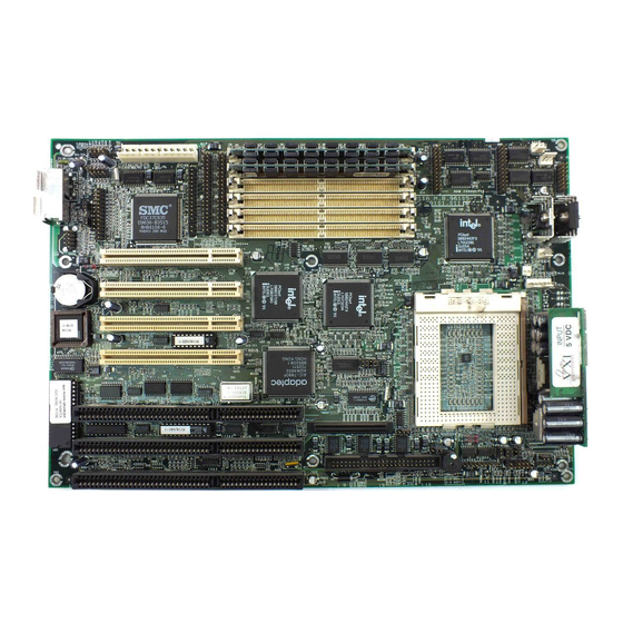
1.2.1 System Board Layout 1 Power connector Buzzer 2 Diskette drive connector Narrow SCSI connector 3 IDE 1 connector Wide SCSI connector 4 IDE 2 connector ISA bus slots 5 SIMM sockets PCI slots 6 RDM connectors BIOS 7 CPU voltage regulators Battery 8 VRM components PS/2 mouse connector... -
Page 18: Jumpers And Connectors
Jumpers and Connectors 1.3.1 Jumper and Connector Locations Figure 1-2 shows the jumper locations on the system board. The blackened pin on a jumper represents pin 1. Figure 1-2 Jumper and Connector Locations The blackened pin of a jumper or connector represents pin 1. -
Page 19: Jumper Settings
1.3.2 Jumper Settings Table 1-1 Jumper Settings Jumper Setting Function BIOS Type Acer BIOS OEM BIOS Password Security Password check 2-3* Password bypass SCSI Selection Open Narrow SCSI Wide SCSI CPU Bus Frequency 60 MHz (150/180 MHz) 2-3* 66 MHz (200 MHz) -
Page 20: Cn13 Settings For Cpu Core/Bus Frequency Ratio
Table 1-2 lists the CPU core over bus frequency ratios depending on CN13 settings. Table 1-2 CN13 Settings for CPU Core/Bus Frequency Ratio CN13 Settings CPU Core / Bus Freq. Ratio 0 = Open 1 = Closed User’s Guide... -
Page 21: Cn14 Settings For Cpu Core Voltage
Table 1-3 lists the CPU core voltages depending on CN14 settings. Table 1-3 CN14 Settings for CPU Core Voltage CN14 Settings CPU Voltage Reserved 0 = Open 1 = Closed DO NOT change the settings of CN14 unless you are qualified to do so. Ask a technician if you need help when configuring these jumpers. -
Page 22: Connector Functions
1.3.3 Connector Functions Table 1-4 lists the different connectors on the system board and their respective functions. Table 1-4 Connector Functions Connector Function COM1 connector COM2 connector Parallel port connector Power connector Diskette drive connector IDE1 connector IDE2 connector CN8, CN9 RDM connectors CN10 Software shutdown power control connector... -
Page 23: Usb Bracket Installation
USB Bracket Installation The system board includes a connector (CN12) for the optional universal serial bus (USB) bracket. The USB bracket has two external special connectors to support additional serial peripherals. The USB bracket is an optional item. Follow these steps to install the USB bracket: Remove the cover of an expansion slot on the housing rear panel. -
Page 24: Esd Precautions
ESD Precautions Always observe following (electrostatic discharge) precautions before installing any system component: Do not remove any system component from its packaging unless you are ready to install it. Wear a wrist grounding strap before handling electronic components. Wrist grounding straps are available at most electronic component stores. -
Page 25: Installing A Pentium Pro Cpu
Installing a Pentium Pro CPU 1.5.1 Installation with the Sliding Heat Sink Follow these installation steps if your CPU board comes with the sliding heat sink: Release the heat sink locks. Attach the heat sink by sliding its rails along the longer sides of the rectangular Pentium Pro CPU. -
Page 26: Installing A Cpu With The Sliding Heat Sink
Lift up the CPU socket lever. Look at the underside of the CPU and note the area where the pins are denser or closely embedded. Gently insert the CPU pins into the socket, matching the denser pins with the denser holes on the socket. -
Page 27: Installation With The Hook-Type Heat Sink
1.5.2 Installation with the Hook-Type Heat Sink Follow these installation steps if your CPU board comes with the hook-type heat sink: Lift up the CPU socket lever. Look at the underside of the CPU and note the area where the pins are denser or closely embedded. - Page 28 Link the rear heat sink hook to the holding tab at the base of the socket, then the front hook to the holding tab on the front. This locks the heat sink and fan to the CPU socket. To remove the heat sink and fan, simply press the upper part of the front heat sink hook inward.
-
Page 29: Memory Upgrade
Memory Upgrade The six 72-pin SIMM sockets onboard support both Extended Data Output (EDO) and fast-page mode SIMMs. You may install 4-MB and 16-MB single-density as well as 8-MB, and 32-MB double-density SIMMs for a total of 192-MB system memory. The SIMM sockets also support 64-MB SIMMs, when available, to achieve 384-MB system memory. -
Page 30: Memory Configurations
1.6.2 Memory Configurations Table 1-5 lists the available memory configurations. Table 1-5 Memory Configurations Bank 1 Bank 2 Bank 3 Total Memory 8 MB 8 MB 16 MB 8 MB 8 MB 4 MB 4 MB 24 MB 8 MB 8 MB 8 MB 8 MB... -
Page 31: Installing A Simm
1.6.3 Installing a SIMM Follow these steps to install a SIMM: Carefully slip a SIMM at a 45° angle into a socket making sure that the curved edge indicating the pin 1 of the SIMM matches pin 1 of the socket. A SIMM fits only in one direction. -
Page 32: Removing A Simm
1.6.4 Removing a SIMM Follow these steps to remove a SIMM: Press the holding clips on both sides of the SIMM outward to release it. Push the SIMM downward to a 45 angle. Pull the SIMM out of the socket. Holding Clip Figure 1-8 Removing a SIMM... -
Page 33: Reconfiguring The System
1.6.5 Reconfiguring the System Reconfigure the system after installing or removing SIMMs. Follow these steps to reconfigure the system: Reboot the system. A memory error message appears, indicating that the total memory does not match the value stored in CMOS. Press during the power-on self-test (POST) routine to run Setup. -
Page 34: Scsi Feature
SCSI Feature The system board features a single-chip SCSI host adapter that adds SCSI I/O capability to the system. The chipset consists of an onboard microcontroller, bus master interface controller, and SCSI controllers. A 50-pin Fast SCSI-II interface with 10 MB/s transfer rate and a 68-pin Wide SCSI interface that transfers at 20 MB/s (Wide SCSI) and 40 MB/s (Ultra SCSI) are also onboard to accommodate various SCSI devices. -
Page 35: Server Management Features (Optional)
Server Management Features (optional) 1.8.1 ASM Pro The ASM Pro is a server management tool based on the Simple Network Management Protocol (SNMP). It detects server problems related to the CPU thermal condition, 5V/3.3V detection, or PCI bus utilization calculation. This feature is designed primarily for server supervisors and management information system (MIS) personnel to help them detect errors or potential trouble spots in their network servers through a... -
Page 36: Remote Diagnostic Management
1.8.2 Remote Diagnostic Management Remote Diagnostic Management (RDM) network management tool that utilizes modems and telephone lines to control a host of servers from a remote station. It monitors and analyzes the server condition, updates the BIOS settings if necessary, or reboots the server in the event of failure and quickly return it to normal operation. -
Page 37: Installing The Rdm Module
Figure 1-9 Installing the RDM Module Insert the cable end with the RDM button into the slot on the housing front panel. Attach the other end of the RDM cable to CN17 (pins 5-6, 11-12) on the system board. Note that the covered pin of the cable connector does not connect to any pin. -
Page 38: Error Messages
Error Messages Do not continue using the computer if you receive an error message of any type. Note the message and take corrective action. This section describes the types of error messages and lists their corresponding corrective measures. There are two general types of error messages: •... - Page 39 Table 1-6 System Error Messages Message Action CMOS Battery Error Replace the battery or contact your dealer. CMOS Checksum Error Run Setup. CPU BIOS Update Code Contact your dealer. Mismatch Diskette Drive Controller Error Check and connect the control or Not Installed cable to the diskette controller.
- Page 40 Table 1-6 System Error Messages (continued) Message Action Memory Error at: Check SIMMs on the system MMMM:SSSS:OOO board. Contact your dealer. (W:XXXX, R:YYYY) where: M: MB, S: Segment, O: Offset, X/Y: write/read pattern Memory Size Mismatch Check the memory size based on the system specifications.
-
Page 41: Correcting Error Conditions
1.9.3 Correcting Error Conditions As a general rule, if an error message says "Press F1 to continue," it is caused by a configuration problem, which can be easily corrected. An equipment malfunction is more likely to cause a fatal error, i.e., an error that causes complete system failure. -
Page 42: Chapter 2 Bios Utility
C h a p t e r BIOS Utility Most systems are already configured by the manufacturer or the dealer. There is no need to run Setup when starting the computer unless you get a Run Setup message. If you repeatedly receive Run Setup messages, the battery may be bad. -
Page 43: Entering Setup
Entering Setup To enter Setup, press the key combination You must press while the system is booting. This key combination does not work during any other time. The BIOS Utility main menu then appears: BIOS Utility Basic System Configuration Advanced System Configuration PCI System Configuration Power Saving Configuration System Security... -
Page 44: Basic System Configuration
Basic System Configuration Select Basic System Configuration to input configuration values such as date, time, and disk types. The following screen shows the Basic System Configuration menu. Basic System Configuration Page 1/2 Date ..... [MM/DD/YY] Time ..... [HH:MM:SS] Diskette Drive A ..[xx-MB xx-inch] Diskette Drive B .. -
Page 45: Date And Time
Press to exit the configuration menu. The following screen shows page 2 of the Basic System Configuration menu. Basic System Configuration Page 2/2 Communication Settings Baud Rate ..... [9600] BPS Parity ......[None] Stop Bits ..... [1] Bits Data Length .... -
Page 46: Diskette Drives
Date Highlight the items on the date parameter and press to set the date following the month-day-year format. Valid values for month, day, and year are: • Month • • Year Time Highlight the items on the time parameter and press to set the time following the hour-minute-second format. -
Page 47: Ide Drives
2.2.3 IDE Drives Move the highlight bar to the IDE Drive 0 parameter to configure the first IDE drive (drive C). Press to display the IDE hard disk types with their respective values. Select the type that corresponds to your drive. Follow the same procedure for the other drives, if any. Choose None if you do not have other drives. -
Page 48: Onboard Ide
Selecting the “User” Option There are cases when you cannot use the option Auto , instead you have to select Choose the option when you have User User installed an hard disk that was previously formatted but does not use the disk native parameters or structure, that is, the disk type may be in the hard disk types list but the number of cylinders, heads, and sectors differ. -
Page 49: System Memory
2.2.5 System Memory The system automatically detects the total amount of onboard memory during the POST and sets the memory parameters accordingly. If you install additional memory, the system automatically adjusts the Total Memory parameter to display the new memory size. 2.2.6 Math Coprocessor The CPU includes a math coprocessor so this parameter shows... -
Page 50: Enhanced Ide Features
2.2.9 Enhanced IDE Features Hard Disk Block Mode This function enhances disk performance depending on the hard disk in use. If you set this parameter to Enabled , it allows data transfer in block (multiple sectors) by increasing the data transfer rate to 256 bytes per cycle. -
Page 51: Large Memory Support Mode
Hard Disk 32-bit Access Enabling this parameter improves system performance by allowing the use of the 32-bit hard disk access. This enhanced IDE feature only works under DOS, Windows 3.x, Windows 95, and Novell NetWare. If your software or hard disk does not support this function, set this parameter to . -
Page 52: Auto Configuration Mode
2.2.13 Auto Configuration Mode When enabled, this parameter automatically sets the system configuration values to their optimized settings. At the same time, it causes the Memory Test parameter to be fixed to Disabled and the shadow RAM regions for system and video BIOS to . -
Page 53: Configuration Table
2.2.16 Configuration Table This parameter allows you to display the configuration table after POST but before booting. The configuration table gives a summary of the hardware devices and settings that BIOS detected during POST. Following is a sample configuration table. CPU/CLK Pentium Pro/xxx MHz Base Memory:... -
Page 54: Advanced System Configuration
Advanced System Configuration The Advanced System Configuration option allows you to configure the advanced system memory functions. Do not change any settings in the Advanced Configuration if you are not a qualified technician to avoid damaging system. The following screen shows page one of the Advanced System Configuration parameters. -
Page 55: Shadow Ram
2.3.1 Shadow RAM The system reserves 384 KB of random access memory (RAM) for the shadow RAM function. This parameter has eight range addresses. When you set these addresses to Enabled , the system BIOS, video BIOS, and I/O ROM functions run directly from the shadow RAM for faster operation. -
Page 56: Ecc/Parity Mode Selection
2.3.4 ECC/Parity Mode Selection This parameter allows you to select , or . The Parity Disabled option allows single-bit error detection and automatic correction. The automatic correction depends on the setting of the parameter Operation of ECC. See section 2.3.5 for details. ECC also detects multiple-bit errors but does not correct them. -
Page 57: Setting For Sna Cards
2.3.6 Setting for SNA Cards System network architecture (SNA) cards are 8-bit IBM-compatible network cards. Should you need to install an SNA card, make sure to set this parameter to Enabled 2.3.7 Memory at 15MB-16MB To prevent memory address conflicts between the system and expansion boards, reserve this memory range for the use of either the system or an expansion board. -
Page 58: Pci System Configuration
PCI System Configuration The PCI System Configuration allows you to specify the settings for your PCI devices. PCI System Configuration Page 1/1 PCI IRQ Setting ... [ Auto INTA INTB INTC INTD * PCI Slot 1.... [--] [--] [--] [--] *PCI Slot 2 ... - Page 59 PCI Slots These parameters allow you to specify the appropriate interrupt for each of the PCI devices. You can assign IRQ3, IRQ4, IRQ5, IRQ7, IRQ9, IRQ10, IRQ11, IRQ12, IRQ14, or IRQ15 to the slots. The items PCI Slot 4 and Onboard SCSI share the same IRQ. Setting an interrupt for the former automatically sets that same interrupt for the latter.
-
Page 60: Vga Palette Snoop
2.4.2 VGA Palette Snoop This parameter permits you to use the palette snooping feature if you installed more than one VGA card in the system. The VGA palette snoop function allows the control palette register (CPR) to manage and update the VGA RAM DAC (Digital Analog Converter, a color data storage) of each VGA card installed in the system. -
Page 61: Power Saving Configuration
Power Saving Configuration The Power Saving Configuration parameters are configurable only if your system supports the power management feature. The following screens show the Power Saving Configuration parameters and their default settings: Power Saving Configuration Page 1/1 Power Management Mode ....[Enabled ] IDE Hard Disk Standby Timer .. -
Page 62: Power Management Mode
2.5.1 Power Management Mode This parameter allows you to reduce power consumption. When this parameter is set to Enabled , you can configure the system timers. Setting to Disabled deactivates the power management feature and all the timers. For system models with RDM module installed, enabling the RDM feature disables the power management parameters. -
Page 63: System Security
System Security The Setup program has a number of security features to prevent unauthorized access to the system and its data. Enter the Setup program and select System Security to display the following screen. System Security Page 1/1 Disk Drive Control Diskette Drive.... -
Page 64: Drive Control Settings
Table 2-1 Drive Control Settings Diskette Drive Setting Description Normal Diskette drive functions normally Write Protect All Sectors Disables the write function on all sectors Write Protect Boot Sector Disables the write function only on the boot sector Disabled Disables all diskette functions Hard Disk Drive Setting Description... -
Page 65: Onboard Communication Ports
2.6.2 Onboard Communication Ports Serial Port 1 Base Address This parameter allows you to set the serial port 1 logical base address. Table 2-2 Serial Port 1 Settings Setting Description 3F8h Serial port 1 with address 3F8h using IRQ4 2F8h Serial port 1 with address 2F8h using IRQ3 3E8h Serial port 1 with address 3E8h using IRQ4... -
Page 66: Parallel Port Settings
only assign 3F8h or 3E8h to serial port 2. Parallel Port Base Address The system has one parallel port. Table 2-4 lists the options for selecting the parallel port address. You also have the option to disable the parallel port. Table 2-4 Parallel Port Settings Setting... -
Page 67: Onboard Ps/2 Mouse (Irq12)
OPERATION MODE This item allows you to set the operation mode of the parallel port. Table 2-5 lists the different operation modes. Table 2-5 Parallel Port Operation Mode Settings Setting Function Standard Parallel Port (SPP) Allows normal speed one-way operation Standard and Bidirectional Allows normal speed operation in a two-way mode... -
Page 68: Setup Password
2.6.4 Setup Password The setup password prevents unauthorized access to the BIOS utility. Setting a Setup Password Make sure that jumper JP5 is set to pins 2-3 (bypass). You cannot enter the BIOS utility if a setup password does not exist and jumper JP5 is set to pins 1-2 (check). - Page 69 Press to exit the System Security screen and return to the main menu. Press to exit the BIOS utility. A dialog box appears asking if you want to save the CMOS data. Select Yes to save the changes and reboot the system. 10.
-
Page 70: Power On Password
Bypassing the Setup Password If you forget your setup password, you can bypass the password security feature by hardware. Follow these steps to bypass the password: Turn off and unplug the system. Open the system housing and set JP5 to pins 2-3 to bypass the password checking. -
Page 71: Load Setup Default Settings
Load Setup Default Settings Use this option to load the default settings for the optimized system configuration. When you load the default settings, some of the parameters are grayed-out with their fixed settings. These grayed parameters are not user-configurable. If you want to change the settings of these items, disable the Fast Boot Mode parameter in the Basic System Configuration menu. -
Page 72: Leaving Setup
Leaving Setup Examine the system configuration values. When you are satisfied that all the values are correct, write them down. Store the recorded values in a safe place. In the future, if the battery loses power or the CMOS chip is damaged, you will know what values to enter when you rerun Setup. -
Page 73: Ide Hard Disk Types
2.10 IDE Hard Disk Types Type Cylinders Heads Sectors Per Track None (indicates SCSI or no hard disk) (reserved) 1024 2-32 User’s Guide... - Page 74 Type Cylinders Heads Sectors Per Track 1023 1001 1024 1013 BIOS Utility 2-33...
- Page 75 Type Cylinders Heads Sectors Per Track 1024 (reserved) 1024 1024 1024 1024 1024 1024 1024 1010 1024 1024 (reserved) 1001 1024 1024 1024 2-34 User’s Guide...
- Page 76 Type Cylinders Heads Sectors Per Track 1011 1016 Auto User BIOS Utility 2-35...
-
Page 77: Chapter 3 System Utilities
C h a p t e r System Utilities This chapter contains information about system utilities that you need when you upgrade your system. These utilities are the AFlash BIOS Utility and SCSISelect Configuration Utility. The AFlash BIOS Utility diskette does not come with the system package. -
Page 78: Executing Aflash
Program flash memory programs Flash memory according to the data loaded in step 1. This function also shows the BIOS checksum and BIOS type to make sure that the operation is correct. AFlash features password security to prevent unauthorized access. 3.1.1 Executing AFlash Follow these steps to execute AFlash:... -
Page 79: Quick Way To Execute Aflash
Select Program Flash Memory to erase the current BIOS, and program Flash ROM. Never turn off the system power while Flash BIOS is programming. This will destroy the BIOS. Reboot the system. 3.1.2 Quick Way to Execute AFlash When you have already copied the AFlash files into your hard disk, you can simply type the following on the DOS prompt (subdirectory where the files are located) to quickly execute the program. -
Page 80: Scsiselect Configuration Utility
SCSISelect Configuration Utility The SCSISelect utility allows you to change SCSI controller settings without opening the system or changing jumpers. 3.2.1 Overview Default Values Table 3-1 lists the settings that you can change using the SCSISelect utility and the default value for each setting. Some settings apply globally to the SCSI controller and all SCSI devices on the bus. -
Page 81: Individual Settings For Scsi Drives
Table 3-2 Individual Settings for SCSI Drives Item Default Initiate Sync Negotiation Maximum Sync Transfer Rate 20 MB/sec. Enable Disconnection Send Start Unit SCSI Command 1 Initiate Wide Negotiation When to Use the SCSISelect Utility Use the SCSISelect utility if you need to do either one of the following: •... -
Page 82: Utility Options
Your screen may show the key sequence as +<Hot Key> instead of +A. The correct sequence is 3.2.2 Utility Options When the SCSISelect utility detects that AIC-7880 SCSI controller in the system, it displays the following Options menu. Figure 3-1 Options Menu Screen Use the keys and press... -
Page 83: Configure/View Host Adapter Settings Screen
Configure/View Host Adapter Settings Menu The Configure/View Host Adapter Settings menu lists three settings under SCSI Bus Interface Definitions and three additional options. Figure 3-2 Configure/View Host Adapter Settings Screen Use the keys to select a parameter. Press to display a pop-up menu with a list of possible settings for the parameter. -
Page 84: Host Adapter Scsi Id Selections
HOST ADAPTER SCSI ID This parameter allows you to change the host controller SCSI ID. Figure 3-3 shows the available IDS for use with the AIC-7880. The default setting is SCSI ID 7, which has the highest priority on the SCSI bus. -
Page 85: Scsi Parity Checking Selections
SCSI PARITY CHECKING Select this option to enable or disable the SCSI parity checking function on the SCSI controller. Figure 3-4 displays the selections. The default setting is Enabled Figure 3-4 SCSI Parity Checking Selections The SCSI controller always checks parity when reading from the SCSI bus to verify the correct transmission of data from the SCSI devices. -
Page 86: Host Adapter Scsi Termination
HOST ADAPTER SCSI TERMINATION This parameter allows you to configure the host controller SCSI termination function. Figure 3-5 shows the possible settings. The default setting is Low OFF/High ON Figure 3-5 Host Adapter SCSI Termination Use the keys then press to make a selection. -
Page 87: Boot Device Configuration
BOOT DEVICE OPTIONS This parameter shows the target ID of your boot device. The default setting is 0 (zero). We recommend that you keep the default setting since most system applications run only in this setting. Figure 3-6 shows the boot device configuration menu. Figure 3-6 Boot Device Configuration System Utilities... -
Page 88: Scsi Device Configuration
SCSI DEVICE CONFIGURATION This parameter allows you to configure details of each SCSI device on the SCSI bus. A screen similar to Figure 4-7 appears. The screen shows a column of information for each SCSI ID, even if some SCSI IDs are not assigned to a device. - Page 89 Initiate Sync Negotiation This option determines whether the SCSI controller initiates synchronous negotiation with the SCSI device. When set to , the SCSI controller initiates synchronous negotiation with the SCSI device. When set to , the SCSI controller does not initiate synchronous negotiation. The SCSI controller, however, always responds to synchronous negotiation if the SCSI device initiates it.
- Page 90 Enable Disconnection This option determines whether the SCSI controller allows a SCSI device to disconnect from the SCSI bus (sometimes called Disconnect/Reconnect). Disconnect/Reconnect allows the SCSI controller to perform other operations on the SCSI bus while the SCSI device is temporarily disconnected. When set to , the SCSI device may disconnect from the SCSI bus.
-
Page 91: Advanced Configuration Options
When set to , the Start Unit Command is sent to the SCSI device at system boot. When set to , each SCSI device powers-up in the normal procedure. The Send Start Unit Command setting is valid only if the host adapter BIOS is enabled. - Page 92 Use the keys to move between options, then press display a pop-up menu with a list of options. Use the keys to select an option, then press Host Adapter BIOS This option enables or disables the SCSI controller BIOS. default setting is Enabled The SCSI controller BIOS must be enabled if you want the system to boot from a SCSI hard disk drive connected to the SCIS controller.
- Page 93 Extended BIOS Translation fro DOS Drives > 1 GByte This option allows you to enable or disable extended translation for SCSI hard disks with a capacity greater then 1 GB. This is valid only if the SCSI controller BIOS is enabled. The default factory setting is Enabled When enabled, this options use the following translation schemes: •...
-
Page 94: Scsi Disk Utilities Screen
Support for Ultra SCSI Speed This option enables wide SCSI data transfers at 40 MB per second. Most hard disk drives or other SCSI devices do not currently support a communication rate this high. If enabled, make sure that the device you installed is capable of running at this rate. - Page 95 Use the keys to move between options, then press display a pop-up menu with a list of values. Use the keys to select a value, then press FORMAT DISK The Format Disk utility performs a low-level format on disk devices. Most SCSI disk devices are preformatted and do not need to be formatted again.
-
Page 96: Configuring Multiple Scsi Controllers
3.2.3 Configuring Multiple SCSI Controllers The following procedure uses AHA- 2940/W/UW SCSI controller as an example. Follow these steps to configure multiple SCSI controllers: Install the boot SCSI controller in the lowest PCI Device number. The Device number is determined by the slot number on the PCI bus. -
Page 97: Disk Drives Over 1 Gbyte
If you are booting from ISA/EISA-based controllers and using AHA-2940 as a secondary device, see your ISA.EISA-based SCSI controller documentation to ensure that the SCSI controller is at the lowest BIOS base address. ISA/EISA-based SCSI controllers with their BIOS enabled boot before the AHA-2940. 3.2.4 Disk Drives Over 1 GByte Extended Translation... - Page 98 When to Use the Extended Translation WITH DOS 5.0 AND ABOVE NetWare 386 (version 3.0 and above) and the version of UNIX do not share the 1024 cylinder limit of DOS and do not require extended translation to support large disk drives and should not be enabled. DRIVES WITH MIXED PARTITIONS Use standard translation (not extended translation) on drive formatted with two or more partitions for different operating systems.
Need help?
Do you have a question about the Altos 900 Pro and is the answer not in the manual?
Questions and answers