Table of Contents
Advertisement
& K D S W H U
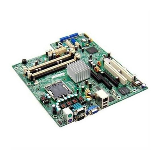
System Board
The V56LA is a high-performance system board with a 64-bit
architecture. It supports the Intel P54C and P55C CPUs running at
100/120/133/150/166/200 MHz.
It
also
supports
6x86/6x86L
Cyrix/IBM and AMD K5/K6 CPUs.
The system board utilizes the
Peripheral Component Interconnect (PCI) local bus architecture that
maximizes
the
system
performance
by
enabling
high-speed
peripherals to match the speed of the microprocessor with its 120 MB
or 132 MB per second transfer rate in burst mode.
A 1-MB or 2-MB SGRAM comes mounted onboard.
Two DRAM
banks composed of four 72-pin sockets come with the board to
support single- and double-density SIMMs for a maximum system
memory of 128 MB.
The SIMM sockets accommodate both the
standard page mode and extended data output (EDO) type SIMMs.
The board supports a 256-KB or 512-KB pipeline burst second-level
cache.
The system board includes a 188-pin connector for the slot board that
contains the PCI and ISA bus slots. The two onboard PCI-enhanced
IDE interfaces with a zero-wait state and 16.6 MB per second transfer
rate support up to four IDE devices. Onboard I/O interfaces comprise
of two UART 16550 serial ports, a parallel port with ECP/EPP feature,
and PS/2 keyboard and mouse ports.
As added enhancements, the board also incorporates a Sound Blaster
Pro-compatible audio subsystem plus plug-and-play (PnP), power
management, and software shutdown features.
System Board
1-1
Advertisement
Table of Contents

Related Manuals for Acer V56LA


Summary of Contents for Acer V56LA
-
Page 1: System Board
& K D S W H U System Board The V56LA is a high-performance system board with a 64-bit architecture. It supports the Intel P54C and P55C CPUs running at 100/120/133/150/166/200 MHz. also supports 6x86/6x86L Cyrix/IBM and AMD K5/K6 CPUs. -
Page 2: Major Components
Major Components The system board has the following major components: A zero-insertion force (ZIF) socket for Intel Pentium and Pentium/MMX, 6x86/6x86L Cyrix/IBM, and AMD K5/K6 Two DRAM banks composed of four 72-pin SIMM sockets that support 4/8/16/32-MB 60/70ns SIMMs 256/512-KB write-back pipeline burst second-level cache 128/256-KB boot block mode Flash ROM for system BIOS, VGA BIOS, and PnP ESCD Two PCI-enhanced IDE interfaces that support up to four IDE... - Page 3 1.1.1 System Board Figure 1-1 shows the locations of the system board major components. RJ-45 connector (optional) Keyboard port Mouse port Serial port 1 Serial port 2 Parallel port Video port Tag SRAM SIMM sockets Figure 1-1 System Board Layout System Board CPU socket Pipeline burst second-level...
- Page 4 1.1.2 Slot Boards The system board comes with a slot board already installed. The slot board carries the PCI and ISA bus slots for system enhancements and future expansion. The slot board may vary in size and layout depending on your system housing.
- Page 5 Figure 1-4 2-PCI/3-ISA Slot Board (for Aspire desktop systems) Figure 1-5 3-PCI/4-ISA Slot Board (for Aspire minitower systems) System Board...
- Page 6 Figure 1-6 3-ISA Slot Board (for AcerBasic system) Refer to the corresponding housing manual for slot board installation instructions. User’s Guide...
-
Page 7: Jumper And Connector Locations
Jumpers and Connectors 1.2.1 Jumper and Connector Locations Figure 1-7 shows the jumper and connector locations on the system board. Figure 1-7 System Board Jumper and Connector Locations The blackened pin of a jumper represents pin 1. System Board... -
Page 8: Jumper Settings
See Table 1-2 for the specific settings of jumpers JP8-JP15 and JP17 when selecting the CPU type and speed. Default setting Function Onboard VGA Disabled Enabled BIOS Type Acer BIOS OEM BIOS Password Security Check password Bypass password Cache Size 256 KB 512 KB... - Page 9 Table 1-2 CPU Type Selection Pentium P-100 P-120 P-133 P-150 P-166 P-200 Pentium ODP/MMX AMD K5 PR120 PR133 PR150 PR166 Cyrix/IBM 6x86 P120+ P150+ P166+ Cyrix/IBM 6x86L P120+ P150+ P166+ System Board Jumper JP13 JP14 JP15 JP17...
-
Page 10: Connector Functions
1.2.3 Connector Functions Table 1-3 lists the different connectors on the system board and their respective functions. Table 1-3 Connector Functions Connector Video port Fax/modem/voice-in connector Audio I/O board connector Line-in for AMC connector Slot board connector ATI media connector CD-in connector CN10 WaveTable connector... -
Page 11: Esd Precautions
Figure 1-8 shows the cables you can connect to the multifunction connector CN17. Power LED Figure 1-8 20-pin Reset/LED Connector (CN17) ESD Precautions Always observe following precautions before installing a system component: Do not remove a component from its antistatic packaging until you are ready to install it. -
Page 12: Memory Upgrade
Memory Upgrade The system board comes with four 72-pin SIMM sockets that support 4-MB and 16-MB single-density SIMMs and 8-MB and 32-MB double- density SIMMs. Table 1-4 lists the possible 64-bit memory configurations. Table 1-4 Memory Configurations (64-bit) Bank 0 SIMM-1 SIMM-2 SIMM-3... - Page 13 The system also supports 32-bit memory configurations. This feature allows you to install only one SIMM in a bank or in a configuration. Table 1-5 shows the 32-bit configurations. Table 1-5 Memory Configurations (32-bit) Bank 0 SIMM-1 SIMM-2 SIMM-3 4 MB 4 MB 4 MB 4 MB...
-
Page 14: Installing A Simm
1.4.1 Installing a SIMM Follow these steps to install a SIMM: Carefully slip a SIMM at a 45 angle into a socket making sure that the curved edge indicating the pin 1 of the SIMM matches pin 1 of the socket. A SIMM fits only in one direction. -
Page 15: Removing A Simm
1.4.2 Removing a SIMM Follow these steps to remove a SIMM: Press the holding clips on both sides of the SIMM outward to release it. Move the SIMM to a 45 angle. Pull the SIMM out of the socket. Figure 1-9 Removing a SIMM Always remove SIMMs from the socket labeled SIMM-4, then SIMM-3, and so on. - Page 16 1.4.3 SIMM Type Selection When selecting SIMMs to install, make sure to take note of the height limitations of the slot board installed in the system. Table 1-6 shows the SIMM height limitations for the different slot boards. Table 1-6 SIMM Height Limitations Slot Board Aspire Desktop and AcerBasic...
-
Page 17: Reconfiguring The System
1.4.4 Reconfiguring the System You must enter Setup after installing or removing SIMMs to reconfigure the system. Follow these steps to reconfigure the system: Turn the system on. A memory error message appears, indicating that the total memory does not match the value stored in CMOS. -
Page 18: Cpu Installation
CPU Installation The system board comes with a zero-insertion force (ZIF) CPU socket for easy installation. Follow these steps to install a Pentium CPU: Lift up the socket lever. Insert the CPU to the socket. Make sure that the notched corner of the CPU matches the pin 1 indicator on the socket. -
Page 19: Video Memory Upgrade
Video Memory Upgrade Larger video memory allows you to display higher resolutions and more colors. The system board comes with a 1-MB video memory onboard upgradable to 2 MB. Second-level Cache Configuration The system board supports 256-KB or 512-KB pipeline burst second- level cache. -
Page 20: Audio Features
Audio Features The system board supports a audio features compatible with Sound Blaster, Sound Blaster Pro, and Windows Sound System. connectors onboard accommodate WaveTable, CD-ROM, and fax-voice modem. You may disable the audio feature in the BIOS Utility. 1.9.1 Installing the Audio-I/O Board The connector CN4 on the system board accommodates the audio-I/O board. - Page 21 1.9.2 Audio-I/O Board Features The audio-I/O board consists of microphone port, line-in port, line-out port, and MIDI/game port. These ports accommodate the external audio devices. Microphone Port Line-in Port Line-out Port MIDI/Game Port Figure 1-12 Audio-I/O Board The internal connectors on the audio-I/O board are useful for system housings with built-in speakers, microphone, amplifier, or auxiliary devices.
- Page 22 1.9.3 WaveTable Daughterboard (Optional) The system board supports a WableTable daughterboard as option. The WaveTable does not come with the basic system. WaveTable daughterboard connectors as the audio-I/O board but comes with enhanced audio features. It bundles chipsets that work together to produce better sound quality.
- Page 23 1.9.4 Audio-I/O Devices Figure 1-14 shows the various devices that you can connect to the audio-I/O board. Joystick MIDI Adapter Speakers Head phones Stereo Amplifier Synthesizer CD Player Microphone Figure 1-14 Audio I/O External Devices System Board 1-23...
- Page 24 1.10 QuickStart Power Saving Feature (for Aspire models only) The system board supports a special power saving feature called QuickStart mode. QuickStart turns off the hard disk, monitor, keyboard, and mouse once you press the power switch for less than four seconds while the system is on.
-
Page 25: Installing Isa Cards
1.11 Installing ISA Cards Both PnP and non-PnP ISA cards require specific IRQs. installing ISA cards, make sure that the IRQs required by these cards are not previously assigned to PCI devices to avoid resource conflicts. Follow these steps when installing ISA cards: 1. -
Page 26: Software Error Messages
1.12 Error Messages Do not continue using the computer if you receive an error message of any type. Note the message and take corrective action. This section explains the different types of error messages and corresponding corrective measures. There are two general types of error messages: Software System 1.12.1... - Page 27 Table 1-9 System Error Messages Message CMOS Battery Error CMOS Checksum Error Display Card Mismatch Diskette Drive Controller Error or Not Installed Diskette Drive Error Diskette Drive A Type Mismatch Diskette Drive B Type Mismatch Equipment Configuration Error Hard disk Controller Error Hard disk 0 Error Hard disk 1 Error Keyboard Error or No...
- Page 28 Table 1-9 System Error Messages (continued) Message Memory Error at: MMMM:SSSS:OOO (W:XXXX, R:YYYY) where: M: MB, S: Segment, O: Offset, X/Y: write/read pattern CPU Clock Mismatch Onboard Serial Port 1 Conflict Onboard Serial Port 2 Conflict Onboard Parallel Port Conflict Pointing Device Error Pointing Device Interface Error...
-
Page 29: Correcting Error Conditions
1.12.3 Correcting Error Conditions As a general rule, if an error message says "Press F1 to continue," it is caused by a configuration problem, which can be easily corrected. An equipment malfunction is more likely to cause a fatal error, i.e., an error that causes complete system failure.
Need help?
Do you have a question about the V56LA and is the answer not in the manual?
Questions and answers