Table of Contents
Advertisement
Quick Links
Advertisement
Table of Contents

Related Manuals for IBM Infoprint 6700 Series


Summary of Contents for IBM Infoprint 6700 Series
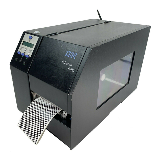
- Page 1 Infoprint 6700 Series Thermal Printer User’s Manual Form Number G550-0449-00...
- Page 3 Infoprint 6700 Series Thermal Printer User’s Manual...
- Page 4 Requests for IBM publications should be made to your IBM representative or to the IBM branch office serving your locality. If you request publications from the address given below, your order will be delayed because publications are not stocked here. Many of the IBM Printing Systems Division publications are available from the web page listed below.
-
Page 5: Notices
Web sites. The materials at those Web sites are not part of the materials for this IBM product and use of those Web sites is at your own risk. IBM may use or distribute any of the information you supply in any way it believes appropriate without incurring any obligation to you. - Page 6 IBM encourages owners of information technology (IT) equipment to responsibly recycle their equipment when it is no longer needed. IBM offers a variety of programs and services to assist equipment owners in recycling their IT products. Information on these product recycling offerings can be found on IBM’s Internet site at...
-
Page 7: Energy Star
IBM Printing Systems Company participates in this program by introducing printers that reduce power consumption when they are not being used. As an... -
Page 8: Trademarks
Trademarks The following terms, denoted by an asterisk (*) in this publication, are trademarks of IBM Corporation in the United States or other countries or both: 6700 ThermaLine The following terms, denoted by a double asterisk (**) in this publication, are... -
Page 9: Communication Statements
Properly shielded and grounded cables and connectors must be used in order to meet FCC emission limits. IBM is not responsible for any radio or television interference caused by using other than recommended cables and connectors or by unauthorized changes or modifications to this equipment. -
Page 10: Industry Canada Compliance Statement
Properly shielded and grounded cables and connectors must be used in order to reduce the potential for causing interference to radio and TV communications and to other electrical or electronic equipment. IBM cannot accept responsibility for any interference caused by using other than recommended cables and connectors. -
Page 11: German Conformity Statement
55024 festgelegt), dann kann es dabei eventuell gestört werden. In solch einem Fall ist der Abstand bzw. die Abschirmung zu der industriellen Störquelle zu öergrvßern. Anmerkung: Um die Einhaltung des EMVG sicherzustellen sind die Geräte, wie in den IBM Handbüchern angegeben, zu installieren und zu betreiben. China Declaration: This is a Class A product. - Page 12 Taiwannese IMPORTANT: This is a Class A product. In a domestic environment this product may cause radio interference in which case the user will be required to take adequate measures. Korea CAUTION: This product is equipped with a 3-wire power cord and plug for the user’s safety.
-
Page 13: Software License Agreement
Lithium Battery CAUTION The controller board contains a lithium battery sealed inside the real- time clock chip. Do not disassemble the chip to replace the battery. Do not dispose of the chip by incineration. Failure to comply may cause the battery to explode. - Page 14 3. No Warranty THE EMBEDDED SOFTWARE IS PROVIDED UNDER THIS LICENSE ON AN "AS IS" BASIS, WITHOUT WARRANTY OF ANY KIND, EITHER EXPRESSED OR IMPLIED, INCLUDING, WITHOUT LIMITATION, WARRANTIES THAT THE EMBEDDED SOFTWARE IS FREE OF DEFECTS, MERCHANTABLE, FIT FOR A PARTICULAR PURPOSE OR NON-INFRINGING.
- Page 15 6. U.S. Government Users The Embedded Software is a "commercial item," as that term is defined in 48 C.F.R. 2.101 (Oct. 1995), consisting of "commercial computer software" and "commercial computer software documentation," as such terms are used in 48 C.F.R. 12.212 (Sept. 1995). Consistent with 48 C.F.R. 12.212 and 48 C.F.R.
-
Page 16: Product Registration Information
Take advantage of special offers • Registration is quick, easy and on-line • Quick links to other IBM on-line sites: new promotions, drivers, software, and more! Register your new IBM printer today: www.ibm.com/printers/register N’attendez pas! Enregistrez votre nouvelle imprimante ou votre dispositif multifunction sur www.ibm.com/printers/register... - Page 17 www.ibm.com/printers/register...
-
Page 19: Table Of Contents
1 Introduction ............25 Requesting IBM Service ..............25 Warnings And Special Information ............26 Manual Conventions ................26 The Infoprint 6700 Series Label Printer ..........27 Standard Features ................ 27 Optional Features................28 Thermal Printer Technology ..............30 The Printing Process ..............30 Dynamic Print Control .............. - Page 20 Table of Contents Using The Optional Internal Rewinder..........60 Batch Rewind Mode ..............60 Label Peel-Off ................66 Removing The Media Guide ............69 Printing Adjustments................70 Printhead Pressure Adjustment ............ 70 Printhead Pressure Block Adjustments ......... 71 Positioning The Media Sensors ............ 72 Sensing Different Media Types .............
- Page 21 Table of Contents Overview ..................163 COAX SETUP..................167 TWINAX SETUP................170 SPC COAX SETUP ................173 SPC TWINAX SETUP ............... 174 IPDS ....................175 TN3270 SETUP ................. 179 TN5250 SETUP ................. 182 IGP/PGL SETUP ................184 IGP/VGL SETUP ................187 P-SERIES SETUP ................
- Page 22 Table of Contents DATE ....................291 Downloading Optional Font Files To Flash Memory ....291 Downloading TrueType Fonts ............. 293 4 Interfaces ............297 Overview.................... 297 Auto Switching ................... 297 Centronics Parallel Interface.............. 298 Centronics Parallel Interface Signals .......... 299 IEEE 1284 Parallel Interface..............
- Page 23 Table of Contents Physical ..................343 Acoustic Specifications ............... 343 Maximum Page Length ............... 343 B Printer Options ..........345 Hardware Options................345 Interface Options ................. 346 Ordering Supplies And Accessories ..........347 Ribbons ..................349 Accessories ................. 349 C ASCII Control Codes......... 351 D Heavy-Duty Media Cutter Installation ....
- Page 24 Table of Contents...
-
Page 25: Introduction
If you are unable to resolve the problem, you may want to request service from your IBM service team. To request service on your IBM 6700 Series Thermal Printer in the U.S. or Canada, call 1-800-IBM-SERV. -
Page 26: Warnings And Special Information
Chapter Warnings And Special Information Warnings And Special Information For your safety and to protect valuable equipment, read and comply with all information highlighted under special headings: DANGER Conditions that could harm you and damage the equipment. DANGER Achten Sie auf folgendes, um keine Personen in Gefahr zu bringen bzw. das Gerät zu beschädigen. -
Page 27: The Infoprint 6700 Series Label Printer
5504-R80 Standard Features ® • Your thermal printer has the standard LinePrinter Plus (LP+) emulation which provides direct compatibility with IBM Infoprint 6700 series printers. ® ® In addition, the printer has co-resident IGP /PGL emulations which provide printer system commands for text, barcodes, graphics, lines, and boxes. -
Page 28: Optional Features
32MB DRAM memory (fixed). • 8MB Flash memory (SIMM). ® • Auto Label Mapping for compatibility with programs written for IBM Line Matrix printers. • Ventless system for operation in environments with airborne particulate matter without compromising performance. • ZGL, TGL, IGL, and STGL Interpreters: PPI/ZGL (Zebra), PPI/TGL... - Page 29 • TN5250/TN3270: The TN5250/TN3270 feature enables your printer to communicate with an IBM host through a Ethernet using the 5250/3270 datastream. This feature allows you to use an application generated for the Twinax/Coax emulation to be printed through the Ethernet. (TN5250/ 3270 is not supported in SL/RFID models).
-
Page 30: Thermal Printer Technology
Chapter Thermal Printer Technology Thermal Printer Technology Quiet and fast, with excellent print quality, your multifunction thermal printer uses an inline thermal printhead. The thermal printer operates differently from a line matrix or laser printer, because the thermal printer uses a printhead with heating elements and special paper or ribbon. -
Page 31: Thermal Consumables
Most of these media options can be die-cut for easy label applications. The wide selection of media sizes and face stocks have been tested with IBM ribbons for print quality and usage. -
Page 32: Setting Up The Printer
Chapter Setting Up The Printer Setting Up The Printer Unpacking The Printer The printer is shipped in a carton and protective bag. The top lid of the carton has instructions for removing the internal packing material. Keep all packing material in case repacking is required. ATTENTION Avoid touching the electrical connectors to prevent electrostatic discharge damage while setting up the printer. - Page 33 Unpacking The Printer Foam 4. Remove the foam pad between the pivoting deck and the frame. Pivoting Deck Platen Deck Lock Lever Printhead Foam Pad 5. Open the pivoting deck by rotating the blue deck lock lever fully clockwise. 6. Remove the foam pad from between the printhead and the platen (rubber roller).
-
Page 34: Installation
Chapter Setting Up The Printer Installation The following sections will guide you through the printer installation process. 1. Place the printer on a flat level surface that allows easy access to all sides of the printer. ATTENTION Never operate the printer while it is resting on its side or upside down. 2. - Page 35 Installation 5. Attach Interface: a. Parallel Interface Attach a suitable parallel printer cable from the computer to the Centronics/IEEE 1284 interface connector at the back of the printer. Snap the bail locks to the Centronics connector to secure the interface cable to the printer. b.
- Page 36 Chapter Setting Up The Printer NOTE: The software turns on the amber status LED at power-up. If a hardware problem is detected at power-up the amber LED will blink continuously. The hardware turns on the green LED at power-up. If a problem is detected with the software stored in the printer’s flash memory both the amber and green LEDs will alternately blink continuously.
- Page 37 Installation If your printer is equipped with the optional Wireless and Optional GPIO it will appear as illustrated below. Wireless And GPIO Interface Panel Wireless Antenna Wireless Interface c. Coax Connection Attach a suitable coaxial cable from the computer to the coax connector located in the I/O plate in the back of the printer.
- Page 38 Chapter Setting Up The Printer...
-
Page 39: Operation
Operation Controls And Indicators Power Switch The power switch is located on the bottom back panel of the printer. To apply power, place the switch in the | (ON) position. When you first power on the printer, a series of initialization messages will appear on the Liquid Crystal Display (LCD) on the control panel. - Page 40 Chapter Controls And Indicators Status and Display Indicators...
- Page 41 Control Panel Control Panel Keys...
- Page 42 Chapter Controls And Indicators Control Panel Keys (cont.)
-
Page 43: Powering On The Printer
Powering On The Printer Powering On The Printer When you power on the printer, it executes a self-test. During the self-test, the LCD momentarily displays the DPI resolution (203 or 300 DPI) of the installed printhead. The default power-on state is online. Once the printer has successfully initialized, the ONLINE status indicator light illuminates, and the LCD indicates the communication interface selected and the type of emulation installed. -
Page 44: Loading Media And Ribbon
Chapter Loading Media And Ribbon • Peel-Off. When the optional internal rewinder is installed, the printer prints and peels die-cut labels from the liner without user assistance. The label liner is wound on the rewinder. The printer waits for you to take away the label before printing the next one (on-demand printing). -
Page 45: Loading Roll Media
Loading Roll Media Loading Roll Media Media Cover Media Hanger Media Hanger Guide Pivoting Deck Media Width Guide Media Damper Deck Lock Lever 1. Open the media cover. 2. Slide the blue media hanger guide outward to the end of the media hanger, and flip it up horizontally. - Page 46 Chapter Loading Media And Ribbon Media Roll Media Hanger Media Hanger Guide 5. Slide a roll of media onto and towards the back of the media hanger. The media feeds from the top of the roll and towards the front of the printer. 6.
- Page 47 Loading Roll Media Media and Ribbon Loading Instruction Media Printhead Media Damper Platen (Rubber Drive Roller) 7. Thread the media under the media damper and then between the platen (rubber drive roller) and the printhead. You can also refer to the arrows on the printer frame or to the label inside the media cover for media loading instructions.
- Page 48 Chapter Loading Media And Ribbon Lower Media Sensor Media Guard Fixed Guide Media Width Guide Media Sensor Handle Media Damper 8. Verify that the left (inside) edge of the media is against the fixed guide on the bottom of the media damper. 9.
- Page 49 Loading Roll Media Upper Sensor Visible Red Beam Lower Sensor Upper Sensor Handle Media Guard Opening 11. Slide the upper sensor directly over the lower sensor. Media (left edge) Guide Notch 12. Align the left (inside) edge of the media with the guide notch located on the front edge of the tear bar.
- Page 50 Chapter Loading Media And Ribbon Pivoting Deck Deck Lock Lever 13. Close the pivoting deck and rotate the deck lock lever fully counterclockwise. This locks the pivoting deck and printhead assembly into the printing position. IMPORTANT Ensure the pivoting deck is down and locked before attempting to advance media or print.
- Page 51 Loading Roll Media For direct thermal operation (no ribbon required): • If you have not run an Auto Calibrate, do so now. See “Running Auto Calibrate” on page 78. • If you have already run an Auto Calibrate, complete the following steps: a.
-
Page 52: Loading Fanfold Media
Chapter Loading Media And Ribbon Loading Fanfold Media Fanfold Media Cover Tension Fanfold Media Media Hanger Pivoting Guide Deck Media Hanger Bottom Panel Opening Deck Lock Lever 1. Open the media cover. 2. Slide the media hanger guide outward to the end of the media hanger and rotate it upward to a horizontal position to remove any roll media. - Page 53 Loading Fanfold Media Media Sensor Media Guard Fixed Guide Media Width Guide Media Sensor Handle Media Damper 8. Slide the media width guide outward to the end of the media damper. 9. Thread the media under the media damper and then between the platen (rubber drive roller) and the printhead.
- Page 54 Chapter Loading Media And Ribbon Media (left edge) Guide Notch 12. Align the left (inside) edge of the media with the guide notch located on the front edge of the tear bar.
- Page 55 Loading Fanfold Media Pivoting Deck Deck Lock Lever 13. Close the pivoting deck and rotate the deck lock lever fully counterclockwise. This locks the pivoting deck and printhead assembly into the printing position. IMPORTANT Ensure the pivoting deck is down and locked before attempting to advance media or print.
- Page 56 Chapter Loading Media And Ribbon For direct thermal operation (no ribbon required): • If you have not run an Auto Calibrate, do so now. See “Running Auto Calibrate” on page 78. • If you have already run an Auto Calibrate, complete the following steps: a.
-
Page 57: Loading Ribbon
Loading Ribbon Loading Ribbon Skip this section for 4 inch DT models or when using direct thermal printing. Ribbon Take-Up Core Ribbon Take-up Spindle Pivoting Deck Ribbon Supply Spindle Ribbon Roll Deck Lock Lever 1. Install the ribbon take-up core on the ribbon take-up spindle. NOTE: The first ribbon take-up core comes with the printer. - Page 58 Chapter Loading Media And Ribbon Ribbon Printhead Media Rear Ribbon Guide Roller 4. Thread the end of the ribbon under the rear ribbon guide roller, then between the platen and the printhead. You can also refer to the arrows on the printer frame or to the upper-right corner of the label inside the media cover for ribbon loading instructions.
- Page 59 Loading Ribbon Media Cover Media and Ribbon Loading Instructions Ribbon Take-up Core Ribbon Take-up Spindle IMPORTANT Do not attach the ribbon to the ribbon take-up spindle without a fiberboard take-up core installed. 5. Attach the ribbon to the ribbon take-up core on the ribbon take-up spindle using the adhesive on the ribbon leader.
-
Page 60: Using The Optional Internal Rewinder
Chapter Using The Optional Internal Rewinder 9. If you have not run an Auto Calibrate with this media and ribbon, do so now. See “Running Auto Calibrate” on page 78. 10. Press the FEED key once to verify that the media and ribbon advance. 11. - Page 61 Batch Rewind Mode Installing The Media Guide The media guide must be installed when using Batch Rewind mode. Front Door Media Guide Hook Groove To install the media guide: 1. Open the front door by pulling it upwards, then forward. 2.
- Page 62 Chapter Using The Optional Internal Rewinder Loading Media Rewinder Release Lever Rewinder 1. To load media, refer to “Loading Roll Media” on page 45 and complete steps 1 through 10.
- Page 63 Batch Rewind Mode Media Media Guide Rewinder Release Lever Slot 2. Thread the media over the front of the media guide and through the opening under the front door toward the internal rewinder. IMPORTANT If you do not complete the following step, it will be extremely difficult to remove the printed labels from the rewinder.
- Page 64 Chapter Using The Optional Internal Rewinder Media Cover Deck Lock Lever 6. Press down on both sides of the pivoting deck and rotate the deck lock lever counterclockwise against its stop to place the printhead assembly into the printing position. 7.
- Page 65 Batch Rewind Mode Removing Printed Media from the Rewinder Release Lever Rewinder Printhead 1. Open the media cover. 2. Press the FEED key to advance the last printed label past the printhead, and tear the liner from behind the last printed label. 3.
-
Page 66: Label Peel-Off
Chapter Using The Optional Internal Rewinder Label Peel-Off You can set up the printer to automatically peel die-cut labels off their liner (backing) and dispense them one at a time while rewinding the liner. You can install the media guide to prevent long labels from accidentally adhering to the front door assembly, but it is normally not needed when using labels less than two inches long (see “Installing The Media Guide”... - Page 67 Label Peel-Off Back Flange Raised Ridge Rewinder Release Lever Slot Liner IMPORTANT If you do not complete the following step, it will be difficult to remove the liner from the rewinder. 6. Turn the release lever on the rewinder counterclockwise and lock it in place.
- Page 68 Chapter Using The Optional Internal Rewinder Media Cover Deck Lock Lever 12. Press down on both sides of the pivoting deck and rotate the deck lock lever fully counterclockwise. 13. Press the FEED key. The label advances to the peel-off position, and “Remove Label”...
-
Page 69: Removing The Media Guide
Removing The Media Guide Removing Label Liner from the Rewinder 1. Open the media cover. 2. Open the front door. 3. Tear the liner at the tear bar. 4. Manually rewind the remaining liner onto the rewinder by turning the rewinder counterclockwise. -
Page 70: Printing Adjustments
Chapter Printing Adjustments Printing Adjustments Printhead Pressure Adjustment Printhead Pressure Adjustment Dial Active Pressure Setting Sometimes you will need to adjust printhead pressure because of variations in media thickness and width. The printhead pressure adjustment dial is shown above. The value shown at the bottom of the dial is the active setting. In general, adjust printhead pressure to the lowest value which produces the desired print quality. -
Page 71: Printhead Pressure Block Adjustments
Printhead Pressure Block Adjustments Printhead Pressure Block Adjustments Right Pressure Block Right Pressure Block Pointer Left Pressure Block Lead Screw Knob Pressure Block Adjustment Scale Left Pressure Block Handle Printhead pressure block adjustments are used to obtain a uniform print density across the width of the installed media under a variety of media and ribbon conditions. -
Page 72: Positioning The Media Sensors
Chapter Printing Adjustments 3. Press the ↵ key to start the Grey test pattern. The pattern will start and continue to print. 4. Press ↵ again to stop printing. 5. Check the test pattern. If necessary reposition the pressure blocks to obtain a uniform print density across the media width. - Page 73 Positioning The Media Sensors Sensing Media with Horizontal Black Marks (Mark) or Media with No Label Length Indicators (Disable) Visible Red Beam from Lower Sensor Lower Sensor Black Mark (underside of media) Sensor Handle Media Guard Opening Sensing Media with Horizontal Black Marks Position the lower media sensor for detecting horizontal black marks located on the underside of media, and position the upper sensor above the lower sensor to provide a consistent background.
- Page 74 Chapter Printing Adjustments Sensing Media with Gaps, Notches, or Holes (Gap) Upper Sensor Visible Red Beam from Lower Sensor Media Guard Opening Position the lower media sensor for detecting gaps, notches, or holes in media with a white background. Place the upper sensor above the lower sensor to provide a consistent background.
- Page 75 Positioning The Media Sensors Sensing Media with Dark Background Labels with Gaps (Advanced Gap) Upper Sensor Visible Red Beam Lower Sensor Upper Sensor Handle Media Guard Opening NOTE: Ribbon is not displayed in this illustration. The upper and lower sensors are designed to function with or without ribbon installed. The upper sensor and lower sensor are used together to detect liner gaps between die cut labels that have a black or dark background on white or clear liner.
- Page 76 Chapter Printing Adjustments Sensing Dark Background Media with Notches or Holes (Advanced Notch) Upper Sensor Upper Sensor Handle Visible Red Beam Lower Sensor Black line on underside of media Media Guard Opening NOTE: Ribbon is not displayed in this illustration. The upper and lower sensors are designed to function with or without ribbon installed.
-
Page 77: Sensing Different Media Types
Sensing Different Media Types Sensing Different Media Types The printer’s media sensors can detect the different types of label length indicators on a large variety of media types. This is accomplished by selecting the correct sensor option: Gap, Mark, Advanced Gap, Advanced Notch, or Disable under Gap/Mark Sensor in the CALIBRATE CTRL menu. -
Page 78: Running Auto Calibrate
Chapter Printing Adjustments Calibrating The Media Sensors Due to manufacturing differences in media and ribbon, the media sensors may have difficulty differentiating between the label and the liner or the label and the black mark. When this occurs, the printer may intermittently skip a label or display a fault message such as “GAP NOT DETECTED/See Manual”... - Page 79 Running Auto Calibrate 1. Press the PAUSE key until “OFFLINE” appears on the LCD. 2. Press ↓ and ↵ together until “ENTER SWITCH UNLOCKED” displays. 3. Press the TEST PRINT key until “Printer Tests/Auto Calibrate” displays. ↵ 4. Press . Media advances until it can accurately detect the label length indicators and then stops at the Top-of-Form position.
-
Page 80: Running Media Profile
Chapter Printing Adjustments Running Media Profile The Media Profile printout shows the relationship of the Paper Out Threshold and the Gap/Mark Threshold values, illustrates if and when each label length indicator is detected, and shows the difference between the label length indicators and the label. -
Page 81: Running Manual Calibrate
Running Manual Calibrate Paper Out(144) Gap Mark(105) Figure 1. Media Profile Printout Running Manual Calibrate Manual Calibrate should be performed only when the values derived from Auto Calibrate fail to improve the media sensors’ ability to sense label length indicators on the installed media. You must first enable “Admin User” in the PRINTER CONTROL menu before accessing or initializing Manual Calibrate in the CALIBRATE CTRL menu. -
Page 82: Cleaning
Chapter Cleaning 6. Press until “CALIBRATE CTRL” displays. ↵ 7. Press ↓ until “Manual Calibrate/Run Calibrate” displays, then press the 8. Follow the instructions displayed on the LCD. Example: “REMOVE RBN&MEDIA/Press Enter” indicates that you must open the pivoting deck and remove the ribbon and media from under the printhead, close and ↵... -
Page 83: General Cleaning
General Cleaning General Cleaning Periodically clean all rollers, guides, and assemblies. Use low pressure air to remove dust in the printer. Use isopropyl alcohol and a cotton swab to clean any areas where media dust, adhesives, etc. have accumulated. Cleaning The Printhead, Platen Roller And Media Sensors NOTE: You do not need to turn off the printer before cleaning the printhead, platen roller, or media sensors. - Page 84 Chapter Cleaning Printhead Pivoting Heating Deck Elements Peel/Tear Door Lower Media Sensor (visible with red LED) Printhead Cover/ Upper Media Sensor Deck Lock Lever Platen Roller Print Element Upper Sensor...
- Page 85 Cleaning The Printhead, Platen Roller And Media Sensors 1. Rotate the deck lock lever clockwise to open the pivoting deck and remove any media and ribbon (if loaded) to gain access to the printhead assembly heating element area. 2. Gently rub the felt tip of the cleaning pen or a cotton swab with Isopropyl alcohol across the printhead heating elements (light brown area).
- Page 86 Chapter Cleaning...
-
Page 87: Configuring The Printer
Configuring The Printer Overview This chapter provides information about: • Setting, saving, modifying, and printing configurations • Configuration menus • Downloading emulation and operating system software Setting Printer Configuration Parameters Configuration parameters are set from the control panel or are retrieved from the printer’s memory. -
Page 88: Selecting A Menu Option
Chapter Overview NOTE: In menus with numeric ranges of more than 50 numbers, hold down the + or − key for more than 2 seconds to move through the range in increments of 5. To move in increments of 1 again, release your hold on the + or −... -
Page 89: Changing Printer Settings
Changing Printer Settings IMPORTANT This change takes effect for all subsequent data and operations for the printer as soon as the ↵ key is pressed and the asterisk (*) is displayed. The configuration change(s) stay in effect only while the printer is powered on. -
Page 90: Saving A Configuration
Chapter Overview 4. Press the ↵ key to select a value. An asterisk (*) displays next to the selected value or option. 5. If there are more submenu values or options you want to change, use the ,↑, ↓, +, and − keys to access the value and the ↵ key to select it. At any time, you may press the key to return to the Main menu. -
Page 91: Specifying A Power-Up Configuration
Specifying A Power-Up Configuration NOTE: If the configuration number has been previously saved and Protect Configs. = Enabled under CONFIG CONTROL, the following error message displays: CONFIG. EXISTS Delete First If the above occurs, see “Modifying A Saved Configuration” on page 92, step 4. -
Page 92: Modifying A Saved Configuration
Chapter Overview Modifying A Saved Configuration You can change a saved configuration by rewriting over it. For example, you can modify Config. 1, shown below. Suppose you want to keep all the settings but you want to select the parallel Centronics interface instead of the IEEE 1284 interface. -
Page 93: Printing A Configuration
Printing A Configuration Then, the following displays when it is deleted: Delete Config. 5. Save the new configuration as described in the “Saving A Configuration” on page 90. Make sure you select the same number (e.g., Config. 1) when saving the modified configuration. The new configuration writes over the existing one. -
Page 94: Loading A Saved Configuration
Chapter Overview Loading A Saved Configuration To use a different configuration: 1. Press the PAUSE key until OFFLINE displays. 2. Press the JOB SELECT key until the desired configuration displays. 3. Press the ↵ key until the desired configuration displays. 4. - Page 95 Loading A Saved Configuration Figure 3. Sample Configuration Printout...
- Page 96 Chapter Overview Sample Configuration Printout (cont.)
- Page 97 Loading A Saved Configuration Sample Configuration Printout (cont.)
- Page 98 Chapter Overview Sample Configuration Printout (cont.)
- Page 99 Loading A Saved Configuration Sample Configuration Printout (cont.)
- Page 100 Chapter Overview Sample Configuration Printout (cont.)
-
Page 101: Menu Overview
Menu Overview Loading A Saved Configuration Menu Overview QUICK RFID VALIDATOR CONFIG. MEDIA SETUP CONTROL CONTROL CONTROL Set the basic RFID encoder Online data Name, store, and Control various menus needed to setup and status validator setup retrieve up to parameters configure the reporting. -
Page 102: Main Menu
Chapter Main Menu Main Menu QUICK RFID VALIDATOR CONFIG. SETUP CONTROL CONTROL (page 113) (page 122) Print Intensity Refer to the RFID Load Config. Refer to the Online Print Speed Save Config. Labeling Reference Data Validator Print Mode Print Config. Manual . - Page 103 Main Menu Loading A Saved Configuration MEDIA CALIBRATE PRINTER CONTROL CTRL CONTROL (page 125) (page 144) (page 151) Print Intensity Gap/Mark Sensor Print File List Print Speed Auto Calibrate LP+ Emulation Auto Locking Print Mode Media Profile CTHI Emulation Set Lock Key Media Handling Sensed Distance Active IGP Emul...
- Page 104 Chapter Main Menu TWINAX SPC COAX SPC TWINAX COAX 2, 3, 4 2, 3, 4 2, 3, 4 1, 3, 4 SETUP SETUP SETUP SETUP (page 170) (page 173) (page 174) (page 167) Primary Sets Primary Sets SPC Type SPC Type Translation Tbl Translation Tbl Logical Buf Size...
- Page 105 Main Menu Loading A Saved Configuration IGP/PGL IPDS 3270 SETUP 5250 SETUP SETUP (page 184) (page 175) (page 179) (page 182) Character Group Default Font Primary Sets Primary Sets Default Code Pag Translation Tbl Translation Tbl Standard Sets Select LPI Code Page Subset Active Char Set Active Char Set...
- Page 106 Chapter Main Menu PPI/ZGL PPI/TGL PPI/IGL IGP/VGL SETUP SETUP SETUP SETUP (page 187) SFCC Refer to the Printer Refer to the Printer Refer to the Printer Power-up ^X Protocol Interpreter Protocol Interpreter Protocol Interpreter ™ ™ ™ Power-up ^F (PPI) ZGL (PPI) TGL (PPI) IGL Power-up ^PY...
- Page 107 Main Menu Loading A Saved Configuration SER MATRIX PPI/STGL P-SERIES P-SERIES XQ 1, 3 SETUP SETUP SETUP SETUP (page 195) (page 190) (page 193) Refer to the Printer Select CPI Select CPI Select CPI Select LPI Select LPI Select LPI Protocol Interpreter ™...
- Page 108 Chapter Main Menu PROPRINTER EPSON FX DIAGNOSTICS 1, 2, 3 1, 2, 3 SETUP SETUP (page 197) (page 199) (page 248) Select CPI Select CPI Printer Tests Select LPI Select LPI Test Count Typeface Typeface Software Build Character Group Character Group Feature File Character Set Character Set...
- Page 109 Main Menu Loading A Saved Configuration USB PORT PARALLEL SERIAL C/T PORT PORT (page 265) PORT (page 256) (page 264) (page 252) Port Type Port Type Port Type Buffer Size in K Data Bit 8 Baud Rate Device Address Timeout PI Ignored Word Length Timeout...
- Page 110 Chapter Main Menu ETHERNET ETHERNET WLAN ETHERNET ADDRESS PORT ADDRESS PARAMS (page 272) (page 266) (page 267) (page 269) IP Address SEG1: NetBIOS Protocol IP Address SEG1: Timeout IP Address SEG2: ASCII Data Port IP Address SEG2: IP Address SEG3: IPDS Data Port IP Address SEG3: IP Address SEG4:...
- Page 111 Main Menu Loading A Saved Configuration KERBEROS WLAN WLAN LEAP PARAMS PARAMS (page 286) (page 275) (page 283) Kerberos Enable Auth Method Signal Strength WEP Key 3 BYTE1: Kerb. Pwd(01-15) Leap User (01-15) Operation Mode WEP Key 3 BYTE2: Kerb. Pwd(16-30) Leap User (16-30) SSID Name(01-15) WEP Key 3 BYTE3:...
- Page 112 Chapter Main Menu BATTERY DATE CONTROL (page 291) (page 288) Battery Monitor Time/Date Time To Go Percent Charge Current Draw Voltage Amp-Hour Used Time To Go Alert High Volt Alert Low Volt Alert NOTES: Does not appear if the CTHI option is installed. Available only when Battery Monitor is set to Enable (in the BATTERY CONTROL menu).
-
Page 113: Quick Setup
QUICK SETUP Loading A Saved Configuration QUICK SETUP QUICK SETUP Print Intensity -15 to 15 Print Speed 6 ips* 1-10 ips Print Mode Transfer* Direct Media Handling Tear-Off Strip* Tear-Off Peel-Off Continuous Paper Feed Shift 0.00 inches* -0.50 to X inches Label Length 2, 4 4 or 6 inches*... -
Page 114: Quick Setup Submenus
Chapter QUICK SETUP QUICK SETUP (cont. from previous page) Save Config. Power-Up Config. Factory* Disable* Enable QUICK SETUP Submenus Print Intensity This option specifies the level of thermal energy from the printhead to be used for the type of media and ribbon installed. Large numbers imply more heat (thermal energy) to be applied for each dot. - Page 115 QUICK SETUP Submenus Media Handling This option specifies how the printer will handle the media (labels or tag stock). • Tear-Off Strip. Printer prints on the media and sends it out the front until the print buffer is empty, then positions the trailing edge of the last label over the tear bar for removal.
- Page 116 Chapter QUICK SETUP • Physical Label Length is the actual measurable length of the label. The following list of different media types explains how the physical label lengths are determined: • Die-cut labels – measurable length of the removable label (leading edge to trailing edge).
- Page 117 QUICK SETUP Submenus Maximum Label Length range is dependent on the Label Width value selected, printhead installed (203 or 300 DPI). See Appendix A for specifications. NOTE: See “Set Label Length” on page 141. Label Width This option specifies the physical width of the image to be printed. The value can be specified in inches or millimeters depending on the setting of the Units submenu under the MEDIA CONTROL menu.
- Page 118 Chapter QUICK SETUP 4 inches FEED 6 inches Leading Edge • Landscape. Landscape refers to horizontal orientation, where the width of a page is greater than its height. The top edge of the image is the left edge of the media. The following illustration is an example, with the operator viewing the front of the printer.
- Page 119 QUICK SETUP Submenus Trailing Edge 4 inches The top edge of FEED the image is parallel to the trailing edge of the 6 inches media. Leading Edge • Inv. Landscape. Inverse Landscape refers to horizontal orientation, where the width of a page is greater than its height. The top edge of the image is the right edge of the media (the left edge of the image is the trailing edge of the media).
- Page 120 Chapter QUICK SETUP • Gap. Select when using media with a liner space between die-cut labels or when using tag stock with notches or holes as label length indicators on white background media. The Top-of-Form position is the leading edge of the die cut label (trailing edge of the gap, notch, or hole). •...
- Page 121 QUICK SETUP Submenus Validator Funct. This menu appears only if a validator is installed. • Enable. The printer will command the validator to begin scanning and errors will be reported. The counters will be incremented while the validator is enabled. •...
-
Page 122: Config. Control
Chapter CONFIG. CONTROL CONFIG. CONTROL CONFIG. CONTROL Load Config. Factory* Save Config. Print Config. Current* Factory Power-Up Delete Config. Power-Up Config. Factory* Protect Configs. Disable* Enable Name Config 1 Name Config 2 Name Config 3 Name Config 4 Name Config 5 Name Config 6 Name Config 7 * = Factory Default... -
Page 123: Config. Control Submenus
CONFIG. CONTROL Submenus CONFIG. CONTROL Submenus Load Config. The printer can store up to eight configurations in memory. This parameter allows you to select and load a specific configuration. The factory default is Factory. Save Config. This option allows you to save up to eight unique configurations to meet different print job requirements. - Page 124 Chapter CONFIG. CONTROL Name Config (1-8) You may specify a 15-character name which can be used to refer to a configuration. The name you enter for a configuration will be used in the Load Config., Save Config., Print Config., Delete Config., and Power-Up Config. menus.
-
Page 125: Media Control
MEDIA CONTROL CONFIG. CONTROL Submenus MEDIA CONTROL MEDIA CONTROL Print Intensity -15 to 15 Print Speed 6 ips* 1-10 ips Print Mode Transfer* Direct Media Handling Tear-Off Strip* Tear-Off Peel-Off Continuous Paper Feed Shift -0.50 to X inches 0.00 inches* Label Length 2, 4 4 or 6 inches*... - Page 126 Chapter MEDIA CONTROL MEDIA CONTROL (cont. from previous page) Print Direction Head First* Foot First Tear-Strip Time 1.0 seconds* .1 to 60.0 seconds Pre-Peel Mode Disable* Enable Pre-Peel Adjust 1.00 inches* 0.00 to 2.00 inches Lbl Missing Flt Enable* Disable Clip Page Enable* Disable...
-
Page 127: Media Control Submenus
MEDIA CONTROL Submenus MEDIA CONTROL (cont. from previous page) Peel-Off Mode Fast* Standard Continuous Mode Standard* Tear-Off Tear Strip Full TOF Detect Fault 3 Labels* 9 Labels 1 Label Ticket Save Mode Disable* Enable TOF Adjust Mode Disable* Enable TOF Adjust 0.00 to 0.40 Inches Notes: * = Factory Default... - Page 128 Chapter MEDIA CONTROL Print Speed This option specifies the speed in inches per second (ips) at which the media passes through the printer while printing. The range is 1 through 10 ips (in increments of 1 ips). The factory default is 6 ips. NOTE: The maximum print speed varies based on maximum printer width and dot per inch (dpi) resolution of the printhead installed (203 or 300 dpi).
- Page 129 MEDIA CONTROL Submenus Paper Feed Shift This option represents the distance to advance (+ shift) or pull back (– shift) the stop position of a label when Tear-Off Strip, Tear-Off, Peel-Off, or Cut media handling option is enabled. The allowable range is -0.50 inches to the current Label Length value setting, up to a maximum of 12.80 inches, in .01 inch increments.
- Page 130 Chapter MEDIA CONTROL When the Logical Label Length is greater than the Physical Label Length and Clip Page = Disable, the printer will continue to print the image onto the next physical label and ignore the gap or mark based on the label length value set in the MEDIA CONTROL menu.
- Page 131 MEDIA CONTROL Submenus Hor Image Shift This option specifies the amount to shift an image horizontally left (-) or right (+) for precise positioning on the label. The actual width of the image is not affected by this parameter. The allowable range is -1.00 through +1.00 inches in .01 inch increments.
- Page 132 Chapter MEDIA CONTROL 4 inches FEED 6 inches Leading Edge • Inv. Portrait. Inverse Portrait refers to vertical page orientation, where the height of a page is greater than its width. The top edge of the image is parallel to the trailing edge of the media. The following illustration is an example, with the operator viewing the front of the printer.
- Page 133 The IGP/Auto Label Mapping feature allows backward compatibility of programs written for 6700 printers using the IBM IGP graphics language. It allows the printer to print two-up (or other multi-up) labels. Instead of printing multiple labels across the printer, it prints the leftmost label and the rightmost label, so the printout will be twice as long but half as wide.
- Page 134 Chapter MEDIA CONTROL Printer Operation: The printer will print the first (leftmost) 4” label first. Once the first label has been completed, the printer will print the second 4” label. These labels will appear vertically adjacent on the form. Thermal Printer Output Line-Matrix Printer Output Label 1 Label 1...
- Page 135 MEDIA CONTROL Submenus Solution #2: The user sets Auto Label Width to 2”, configures the Num Auto Labels to 3, and enables the Auto Label Mapping feature. Printer Operation for Solution #2: The printer will print the first 2” label by itself, the second 2”...
- Page 136 Chapter MEDIA CONTROL Example 4: Blank Label Case Problem: A file exists with two horizontally adjacent 4” labels. The user now wants to use this file with a printer that has a 4” physical width. The user decides to set the Num Labels to 3 and the Label Width to 4” despite the fact that these values are not optimum.
- Page 137 MEDIA CONTROL Submenus Slew Speed The speed at which the printer moves media without actually printing on it. • Automatic. Always the same as the print speed (see “Print Speed” on page 114). • Manual. Allows you to set the slew speed. The maximum speed depends on your printer model (see Table 18 on page 337).
- Page 138 Chapter MEDIA CONTROL Table 5. Foot First Print Direction Result in Active IGP/ZGL Orientation Option Option Emulation Foot First Portrait Portrait Foot First Landscape Inv. Landscape Foot First Inv. Portrait Inv. Portrait Foot First Inv. Landscape Landscape The factory default is Head First when IGP/PGL or IGP/VGL is enabled. The factory default is Foot First when PPI/ZGL is enabled.
- Page 139 MEDIA CONTROL Submenus Lbl Missing Flt Allows the Label Taken Sensor to first detect the presence of a label at the tear bar for Peel and Tear Off Media Handling Mode only. • Enable. The printer generates a fault condition if a missing label is encountered.
- Page 140 Chapter MEDIA CONTROL When Clip Page is set to Disable, the printer ignores any pre-printed dark marks or multiple gaps on a label that could mistakenly be detected as the next top-of-form position based on the specified Label Length value. The Label Length option is in the MEDIA CONTROL menu.
- Page 141 MEDIA CONTROL Submenus Ribbon Low When eanbled and the amount of ribbon remaining on the supply spindle is approximately 75 to 50 meters or less, the Online status indicator flashes and “Ribbon Low” displays on the second line of the LCD. A Ribbon Low warning message will not prevent printing.
- Page 142 Chapter MEDIA CONTROL Peel-Off Mode When Peel-Off Media Handling mode (see page 128) is enabled, this feature allows selection of two different media motions for automatic label peel-off. • Fast. Reverse and forward media motion distance in Peel-Off mode is reduced, providing faster throughput.
- Page 143 MEDIA CONTROL Submenus Ticket Save Mode This option determines the action of the media for Continuous (std), Tear-Off, Tear-Off Strip and Cut Media Handling Modes after the printer is first powered up or after the printhead has been opened and then closed. When enabled, this option eliminates wasting label(s) or ticket stock when the printer advances media to search for the next TOF position.
-
Page 144: Calibrate Ctrl
Chapter CALIBRATE CTRL CALIBRATE CTRL CALIBRATE CTRL Gap/Mark Sensor Disable* Mark Advanced Gap Advanced Notch Auto Calibrate Run Calibrate Media Profile Print Profile Sensed Distance 0.00 inches Gap/Mark Thresh 171* 000 to 255 Paper Out Thresh 136* 000 to 255 Paper Out Sensor Reflective* Transmissive... -
Page 145: Calibrate Ctrl Submenus
CALIBRATE CTRL Submenus CALIBRATE CTRL Submenus Gap/Mark Sensor The available options specify the sensor type needed for detecting the Top-of- Form position on media with label length indicators (gaps, notches, holes, or black marks). • Disable. Select when using media with no label length indicators (no gaps, notches, holes, or black marks), or when you want the printer to ignore all existing label length indicators on the installed media. - Page 146 Chapter CALIBRATE CTRL Auto Calibrate is completed successfully when the Sensed Distance displayed correctly matches that of the installed media. When Gap is selected, the Sensed Distance should match the length from the trailing edge of one gap to the trailing edge of the next gap (one label + one gap). When Mark is selected, the Sensed Distance should match the length from the leading edge of one black mark to the leading edge of the next black mark.
- Page 147 CALIBRATE CTRL Submenus Threshold Range This option allows the user to select the optimal threshold range for the label stock in use. The printer defaults to using a threshold range of 50% of the positive going pulse (see Media Profile) that represents each gap, notch or mark detected after doing an Auto or Manual Calibrate.
- Page 148 Chapter CALIBRATE CTRL Manual Calibrate is completed successfully when the displayed Sensed Distance correctly matches that of the installed media. When Gap is selected, the Sensed Distance should match the length from the trailing edge of one gap to the trailing edge of the next gap (or one label + one gap). When Mark is selected, the Sensed Distance should match the length from the leading edge of one black mark to the leading edge of the next black mark.
- Page 149 CALIBRATE CTRL Submenus The options for Gap Windowing are Enable and Disable: • Enable. When the leading edge of a gap is detected, the printer ignores the first 90% of the gap length value specified in the Gap Length menu option.
- Page 150 Chapter CALIBRATE CTRL Min Calib Delta Minimum Calibrate Delta changes the minimum threshold value the sensor(s) require to detect the difference between the label and a gap, notch, hole or black mark. This allows bolder gaps (such as notches or holes) to be used as the TOF while intermediate gaps (liner) can be ignored.
-
Page 151: Printer Control
PRINTER CONTROL CALIBRATE CTRL Submenus PRINTER CONTROL PRINTER CONTROL Enable Disable* P-Series* P-Series XQ Serial Matrix Proprinter XL Epson FX LP+ Emulation page 190 page 193 page 195 page 197 page 199 CTHI Emulation Simp Prot Conv Standard* Active IGP Emul IGP/PGL* PPI/ZGL PPI/TGL... - Page 152 Chapter PRINTER CONTROL PRINTER CONTROL (cont. from previous page) Save Char to Fls Del Char frm RAM Ld Char at PwrUp Disable* Enable Del Set frm Flsh Ld Set from Flsh Save Set to Flsh Del Set from RAM Ld Set at PwrUp Disable* Enable Overwrite Files...
-
Page 153: Printer Control Submenus
PRINTER CONTROL Submenus PRINTER CONTROL (cont. from previous page) Max Cached Char 01 KBytes* 01 to 20 KBytes Standard Chars. 340* 0 to 512 Bold Chars. 448* 0 to 512 Extra Bold Char. 504* 0 to 512 OCR-A Chars. 384* 0 to 512 OCR-B Chars. - Page 154 AS/400* • 327x Control Units The SPC will support the same models for Twinax as the IBM 6700 printer. The printer emulations supported by the SPC are Twinax 5225 and Coax 3287. The SPC also provides a range of interfaces available in your thermal printer: Centronics, serial, coax, and twinax.
- Page 155 PRINTER CONTROL Submenus Host Interface This option allows you to send print jobs through any interface with auto- switching selected as host interface. It also allows a particular interface from the menu to be selected. The options are Auto Switching, Centronics, Serial, IEEE 1284, Twinax, Coax, Ethernet and USB.
- Page 156 Chapter PRINTER CONTROL Ld Char from Fls This option loads downloaded character(s) from flash memory. Save Char to Fls This option saves downloaded character(s) to flash memory. Del Char frm RAM This option deletes downloaded character(s) from RAM. Ld Char at PwrUp This option loads downloaded character(s) from flash memory at Power Up.
- Page 157 PRINTER CONTROL Submenus Power-up State • Online. The printer powers up in the online state. • Offline. The printer powers up in the offline state. This selection must be saved as a power-up configuration to be used. The factory default is Online. Ptx Setup SFCC Allows you to choose the hex value of the ASCII character you wish to use as the SFCC for the PTX SETUP command.
- Page 158 • Default. Use for optimum performance. • Laser. Forces the output to correspond with the IBM laser line of printers. • P5000. Forces the output to correspond with the 6500 line of line matrix printers.
- Page 159 PRINTER CONTROL Submenus Admin User • Disable. • Enable. When enabled, this function permits access to submenu items which would not normally be changed by a typical user. The factory default is Disable. Auto Locking Disable. The ↵ (ENTER) key must be locked manually. •...
- Page 160 Chapter PRINTER CONTROL Glob Mem Adjust This menu allows you to adjust the ratio of global memory allocated to label size versus PGL forms, fonts, and logos. For example, when using short labels, you can allocate more memory to forms, fonts, and logos by increasing the Glob Mem Adjust value.
- Page 161 PRINTER CONTROL Submenus Max Cached Char The Maximum Cached Characters option specifies the size of the largest character that can be stored in the font cache. To calculate the memory requirement, use this equation: average horizontal resolution vertical resolution character height character width (inches) x (inches)
- Page 162 Chapter PRINTER CONTROL OCR-A Chars. Character weight adjustment of resident OCR-A characters. The range is 0-512, and the factory default is 384. OCR-B Chars. Character weight adjustment of resident OCR-B characters. The range is 0-512, and the factory default is 304. Tall Characters Increases the point height of resident Intellifont characters.
-
Page 163: Emulations
Manual. IMPORTANT BEFORE you reconfigure an emulation, print a configuration sheet to see all current settings. Standard C/T Interface With a standard coax interface, the printer emulates the following IBM coax printer models: • 3287 Models 1 and 2 •... -
Page 164: Simple Protocol Converter
The PGL emulation is the software based Printronix Graphics Language (PGL) for the IBM thermal printer family. It is based upon, and compatible with, the IGP-100/200/400 board. It includes the following features: On-Line Form and Label Generation makes it easy to create forms or labels with a “preprinted”... - Page 165 EMULATIONS Overview Alphanumeric data can appear as prepositioned “fixed” information (entered when the form is created), be overlayed onto the form (positioned in a specific location after the form is created), or may be dynamically merged with the form. Selectable Bar Codes provide you with the appropriate bar code for your application using standard wide-to-narrow ratios.
- Page 166 Chapter EMULATIONS Variable Bar Codes allow the bar code for your application to print with standard or user-defined ratios in vertical or horizontal orientations. Available bar codes are: Codabar, Code 39, Code 93, Code 128 with Subsets A, B, and C, and Code EAN/UCC 128, EAN 8, EAN 13, Interleaved 2 of 5, MSI, UPC-A, UPC-E, POSTNET, PostBar, Royal Mail, and UPC Shipping.
-
Page 167: Coax Setup
COAX SETUP Overview COAX SETUP 1, 2, 3 COAX SETUP Primary Sets See page 169 Translation Tbl (page 242) (page 232) (page 232) Buffer Reprint (page 206) Buffer Print Disable* Enable (page 206) Coax Type 4234* 3287 (page 212) Active Char Set Secondary Set* Primary Set (page 202) - Page 168 Chapter COAX SETUP COAX SETUP (cont. from prev. page) Last Char = FF (page 229) Null Suppression Off* (page 231) FF Validity Off* (page 220) Auto Skip At End Off* (page 204) FF After Job Off* (page 219) CR, EM, & NL (page 213) Translate Table Default*...
- Page 169 COAX SETUP Overview Coax Setup - Primary Sets and Secondary Sets COAX SETUP Primary Sets (from page 167) 0037 English US* 0880 Cyril. Old 0037 Eng Nether 0423 Greek Old 0285 English UK 875 Gr New Euro 0273 Austr/Germ 0871 Icelandic 0274 Belg.
-
Page 170: Twinax Setup
Chapter TWINAX SETUP TWINAX SETUP 1, 2, 3 TWINAX SETUP Primary Sets (page 172) Translation Tbl (page 243) Buffer Print Disable* Enable (page 206) Twinax Type IPDS 256 Bytes* IPDS 1024 Bytes 5225 4234 (page 243) Active Char Set Secondary Set* Primary Set (page 202) Secondary Sets... - Page 171 TWINAX SETUP Overview 1, 2, 3 TWINAX SETUP (cont. from prev. page) Graphic Chek Cod 40 to FE (page 222) LAC Option Enable* Disable (page 228) LAC Approx. (page 228) Set Text Orientn Control By Host* Left to Right Right to Left (page 239) Host Override Disable*...
- Page 172 Chapter TWINAX SETUP Twinax Setup - Primary Sets and Secondary Sets TWINAX SETUP Primary Sets (from page 170) 0037 English US* 0871 Icelandic 0037 Eng Nether 0290 Japan Kata 0500 Swiss Bil 0870 Latin 2 0500 Belg. New 0838 Thai 0273 Austr/Germ 1026 Turkish 0274 Belg.
-
Page 173: Spc Coax Setup
SPC COAX SETUP Overview SPC COAX SETUP SPC COAX 1, 2, 3 SETUP SPC Type PTX NI* Avatar Comp (page 241) Logical Buf Size 1920* 2560 3440 3564 (page 230) Intervention Req Send To Host* Do Not Send (page 228) Buffer Print Disable* Enable... -
Page 174: Spc Twinax Setup
SPC TWINAX SETUP SPC TWINAX 1, 2, 3 SETUP SPC Type MODE PTX NI* MODE 219 MODE P5000 MODE IBM (page 241) SFCC Char Set 1 <%>* Set 2 ^^$ Set 3 _%_ User Defined (page 239) User Defined St1... -
Page 175: Ipds
IPDS SETUP Overview IPDS IPDS Default Font See page 176 Default Code Pag See page 176 Code Page Subset Version 0* Version 1 (page 212) Emulation 4028 IPDS* 3816 IPDS (page 216) Early Print Comp Off* (page 216) Host Form Length Disable* Enable (page 225) - Page 176 Chapter IPDS IPDS Setup - Default Font and Default Code Pag IPDS SETUP Default Font (from page 175) Courier 10* Times Roman 8 Prestige 10 Times Roman 10 Courier it 10 Times Roman 12 OCRA Times Roman B10 APL 12 Times Roman B12 Courier 12 Times Roman B14...
- Page 177 IPDS SETUP Overview IPDS Setup - Print IPDS Fonts This feature allows you to print a list of all resident fonts currently available in the active IPDS emulation (4028 or 3816). 5504 Figure 4. IPDS Fonts - 4028 Emulation Sample Printout...
- Page 178 Chapter IPDS IPDS Setup - Print IPDS Fonts (cont.) 5504 Figure 5. IPDS Fonts - 3816 Emulation Sample Printout...
-
Page 179: Tn3270 Setup
TN3270 SETUP Overview TN3270 SETUP 3270 SETUP Primary Sets (page 181) Translation Tbl (page 243) Active Char Set Secondary Set* Primary Set (page 202) Secondary Sets (page 181) Early Print Cmpl Disable* Enable (page 216) Alt. Set 80-9F Printable* Control Code (page 203) Intervention Req Send To Host*... - Page 180 Chapter TN3270 SETUP 3270 SETUP (cont. from page 179) FF After Job Off* (page 219) CR , EM, & NL (page 213) Host Override Disable* Enable (page 225) Format Control Disable* Enable (page 221) Lead-in Chars Set 1 <%>* Set 2 ¬¬$ Set 3 _%_ User Defined (page 229)
- Page 181 TN5250 SETUP Overview TN3270 Setup - Primary and Secondary Sets Primary Sets (from page 179) 0037 English US* 0880 Cyril. Old 0037 Eng Nether 0423 Greek Old 0285 English UK 875 Gr New Euro 0273 Austr/Germ 0871 Icelandic 0274 Belg. Old 0290 Japan Kata 0275 Brazilian 0870 Latin 2...
-
Page 182: Tn5250 Setup
Chapter TN5250 SETUP TN5250 SETUP 5250 SETUP Notes: * = Factory Default Italicized items are available only when you Primary Sets enable Admin User (in the PRINTER (page 183) CONTROL menu). This menu appears only if the TN5250 option and the correct security key is Translation Tbl (page 243) installed. - Page 183 IGP/PGL SETUP TN5250 SETUP Overview TN5250 Setup - Primary and Secondary Sets 5250 SETUP Primary Sets (from page 183) 0037 English US* 0871 Icelandic 0037 Eng Nether 0290 Japan Kata 0500 Swiss Bil 0870 Latin 2 0500 Belg. New 0838 Thai 0273 Austr/Germ 1026 Turkish 0274 Belg.
-
Page 184: Igp/Pgl Setup
Chapter IGP/PGL SETUP IGP/PGL SETUP IGP/PGL SETUP Character Group Standard Sets* Arabic Sets Cyrillic Sets European Sets (page 208) Greek Sets Hebrew Sets Turkish Sets UTF-8 Standard Sets 0) ASCII* 1) German 2) Swedish 3) Danish 4) Norwegian 5) Finnish (page 208) 6) English 7) Dutch... - Page 185 IGP/PGL SETUP Overview IGP/PGL SETUP (cont. from prev. page) PI Slew Range (page 232) CR Edit Disable* Enable (page 213) Skip Cmd Prefix Enable* Disable (page 240) Ignore Text Disable* Enable (page 227) Power on IGP/PGL Enable* Disable (page 233) Ext Execute Copy Disable* Enable...
- Page 186 Chapter IGP/PGL SETUP IGP/PGL SETUP (cont. from prev. page) PGL Normal LP+ Menu* PGL Menu (page 232) UPC Descenders Always* Never Only With PDF (page 244) I-2/5 Selection Leading Zero* Trailing Space X2 DPD Modulo 7 CD (page 226) User-Def Ratio Enable* Disable (page 245)
-
Page 187: Igp/Vgl Setup
IGP/VGL SETUP Overview IGP/VGL SETUP IGP/VGL SETUP SFCC 17 to 255 (page 239) Power-up ^X Disable* Enable (page 233) Power-up ^F Disable* Enable (page 233) Power-up ^PY Disable* Enable (page 233) 6 to 10 (page 230) Btm Margin Ctl LP+ Menu* VGL Text Length (page 205) Text Length... - Page 188 Chapter IGP/VGL SETUP IGP/VGL SETUP (cont. from prev. page) UPC Descenders Enable* Disable (page 244) Select SO Char 0 to 255 (page 238) Rot. Char Size Adjusted* Not Adjusted (page 237) Ignore Spaces Disable* Enable (page 227) Ignore ^Lxx Cmd. Disable* Enable (page 227)
- Page 189 IGP/VGL SETUP Overview IGP/VGL SETUP (cont. from prev. page) Ignore Ch#1 0 to 255 (page 226) Ignore Ch#2 0 to 255 (page 226) Data Bit 8 Enable* Disable (page 214) Cmd Resolution Low Resolution* High Resolution (page 212) ^Dnn Dot Slew Low Resolution* High Resolution (page 201)
-
Page 190: P-Series Setup
Character Group Standard Sets* Arabic Sets Cyrillic Sets European Sets (page 210) Greek Sets Hebrew Sets Turkish Sets UTF-8 Character Set* IBM PC* Multinational ECMA Latin 1 DEC Mult. CP 858 EURO (page 210) Primary Subset* ASCII (USA)* French German English... - Page 191 PSeries SETUP Overview P-SERIES SETUP (cont. from prev. page) Top Margin 0* linespaces 0 to 451 linespaces (page 242) Bottom Margin 0* linespaces 0 to 451 linespaces (page 205) Print Char. Set (page 234) Define CR code CR = CR* CR = CR + LF (page 214) Auto LF...
- Page 192 Chapter P-SERIES SETUP P-SERIES SETUP (cont. from prev. page) Text Position Bottom of Line* Top of Line (page 242) Host Command Enable* Ignore All Ignore CPI Ignore LPI (page 224) Reset Cmd CFG Ld Disable* Power up config Current config Factory config (page 236) 1, 2...
-
Page 193: P-Ser Xq Setup
P-SER XQ SETUP Overview P-SER XQ SETUP P-SER XQ SETUP Select CPI 10.0 CPI* 12.0 CPI 13.3 CPI 15.0 CPI 17.1 CPI 20.0 CPI (page 237) Select LPI 6.0 LPI* 8.0 LPI 10.3 LPI (page 238) Typeface Letter Gothic* Courier OCR-A OCR-B (page 244) - Page 194 Chapter P-SER XQ SETUP P-SER XQ SETUP (cont. from prev. page) Control Code 06 8.0 LPI* 10.3 LPI 6.0 LPI Notes: (page 212) * = Factory Default Compressed Print All three Form Length Char 01 SOH* Char 03 ETX Char 09 HT (page 212) submenus work in conjunction.
-
Page 195: Ser Matrix Setup
Character Group Standard Sets* Arabic Sets Cyrillic Sets European Sets (page 210) Greek Sets Hebrew Sets Turkish Sets UTF-8 Character Set* IBM PC* Multinational ECMA Latin 1 DEC Mult. CP 858 EURO (page 210) Primary Subset* ASCII (USA)* French German English... - Page 196 Chapter SER MATRIX SETUP SER MATRIX SETUP (cont. from prev. page) Define CR code CR = CR* CR = CR + LF (page 214) Auto LF Enable* Disable (page 203) Define LF code LF = LF* LF = CR + LF Notes: (page 215) * = Factory Default...
-
Page 197: Proprinter Setup
PROPRINTER SETUP Overview PROPRINTER SETUP PROPRINTER SETUP Select CPI 10.0 CPI* 12.0 CPI 13.3 CPI 15.0 CPI 17.1 CPI 20.0 CPI (page 237) Select LPI 6.0 LPI* 8.0 LPI 10.3 LPI (page 238) Typeface Letter Gothic* Courier OCR-A OCR-B (page 244) Character Group Standard Sets* Arabic Sets... - Page 198 Chapter PROPRINTER SETUP PROPRINTER SETUP (cont. from prev. page) Notes: Define CR code CR = CR* CR = CR + LF * = Factory Default (page 214) All three Form Length submenus work in conjunction. When you Auto LF Enable* Disable change the default in one (page 203)
-
Page 199: Epson Fx Setup
Greek Sets Hebrew Sets Turkish Sets UTF-8 Character Set* Epson Set* OCR-A OCR-B Multinational (page 207) Code Page 850 CP 858 EURO IBM PC Epson Set* ASCII (USA)* French German English Danish I Swedish (page 207) Italian Spanish I Japanese... - Page 200 Chapter EPSON FX SETUP EPSON FX SETUP (cont. from prev. page) Bottom Margin 0* linespaces 0 to 451 linespaces (page 205) Print Char. Set (page 234) Notes: Define CR code * = Factory Default CR = CR* CR = CR + LF (page 214) When the CTHI option is installed, the factory default is Printable.
-
Page 201: Emulation Submenus
Emulation Submenus Overview Emulation Submenus NOTE: The following descriptions are grouped together for all emulations and are listed in alphabetical order. ^Dnn Dot Slew (From page 188.) • Low Resolution. Sets the dot slew command dot values to be interpreted as 60 dpi P-Series dots. - Page 202 Chapter Emulation Submenus Absorb After ^PY (From page 187.) • Absorb Motion. The paper motion line terminator immediately following the graphics ^PY command will be ignored. • Absorb All. The system ignores all the data following ^PY until a host generated terminator is detected and ignored.
-
Page 203: Append Rotated
Emulation Submenus Overview Alt. Set 80-9F (Coax, Twinax, TN3270, TN5250) (From page 167, page 170, page 179, page 182.) • Printable. Prints data in the range of hex 80 through hex 9F. • Control Code. Interprets data in the range of hex 80 through hex 9F as a control code. -
Page 204: Auto Uppercase
Chapter Emulation Submenus Auto Skip at End (From page 168, page 179.) Specifies whether to perform an automatic form feed at the end of a print buffer. If form feed is the last character in the print order, the form feed function is supplied by the Auto Skip At End option. •... -
Page 205: Barcode Errors
Emulation Submenus Overview Barcode Errors (From page 188.) • Enable. An error message will print when invalid bar code data is encountered. • Disable. VGL will not print an error for illegal bar code data; the bar code will be skipped. NOTE: When Barcode Errors is disabled, the VGL emulation will try to make the best use of invalid data by either truncating extra digits or adding zeros to the end of bar code data to meet minimum data length... - Page 206 Chapter Emulation Submenus Buffer Print (From page 167, page 170, page 173, page 174.) • Disable. The printer will print normally. • Enable. The printer prints the EBCDIC data and control codes received from the host as hex values. NOTE: Use of this parameter may alter print attributes set by the host computer.
- Page 207 Aptec CP715 Ukrainian Code Page 865 Greek 437 CP 786 Bulgarian Code Page 860 Greek 8859-7 IBM CP864 Win. CP 1251 Latin 1 8859-1 Win. CP 1253 IBM CP1046 Latin 5 8859-9 Greek 813 EURO Arabic Lam One Latin 9 8859-15...
- Page 208 Code Page 865 Greek 437 8) French CP 786 Bulgarian Code Page 860 Greek 8859-7 9) Spanish IBM CP864 Win. CP 1251 Latin 1 8859-1 Win. CP 1253 10) Italian IBM CP1046 Latin 5 8859-9 Greek 813 EURO 11) Turkish...
- Page 209 Code Page 865 Greek 437 8) French CP 786 Bulgarian Code Page 860 Greek 8859-7 9) Spanish IBM CP864 Win. CP 1251 Latin 1 8859-1 Win. CP 1253 10) Italian IBM CP1046 Latin 5 8859-9 Greek 813 Euro 11) Turkish...
- Page 210 Aptec CP715 Ukrainian Code Page 865 Greek 437 CP 786 Bulgarian Code Page 860 Greek 8859-7 IBM CP864 Win. CP 1251 Latin 1 8859-1 Win. CP 1253 IBM CP1046 Latin 5 8859-9 Greek 813 EURO Arabic Lam One Latin 9 8859-15...
- Page 211 Aptec CP715 Ukrainian Code Page 865 Greek 437 CP 786 Bulgarian Code Page 860 Greek 8859-7 IBM CP 864 Win. CP 1251 Latin 1 8859-1 Win. CP 1253 IBM CP 1046 Latin 5 8859-9 Greek 813 EURO Arabic Lam One...
- Page 212 Chapter Emulation Submenus Character Set (P-Series, Serial Matrix, Proprinter, Epson FX) (From page 190, page 195, page 197, page 199.) This item allows selection of the character set to be used by the printer. Cmd Resolution (From page 188.) • Low Resolution.
-
Page 213: Copy Count
Emulation Submenus Overview Copy Count (From page 187.) Determines the number of identical copies of each physical page that will be printed. The range is 1-999, and the factory default is 1. CR at MPP+1 (From page 167, page 179.) MPP is Maximum Print Position, which is also known as line length. - Page 214 Chapter Emulation Submenus Data Bit 8 (From page 188.) • Enable. The PI line is not passed directly from host to printer; all 8 bits are used for data bits, and characters in the hex 80-FF range can be accessed. •...
- Page 215 Emulation Submenus Overview • CR = CR. Does not insert an extra line feed after each carriage return. • CR = CR + LF. Inserts an extra line feed after each carriage return. The next print position will be print position 1 of the next line. The factory default is CR = CR.
- Page 216 Chapter Emulation Submenus Early Print Cmpl (Coax, TN3270) (From page 167, page 179.) Early Print Complete capability allows the printer to send print (order) complete status to the host before the printer is actually done printing all data. This option is valid only when the printer is in DSC/DSE mode.
-
Page 217: Error Report
Emulation Submenus Overview Error Markers (From page 188.) • Enable. Prints the following error markers for those elements that print beyond the page boundaries: >> for elements that begin off the right side of the page; << for elements that begin at the indicated position but end off the page; ♦... - Page 218 Chapter Emulation Submenus ESC d command (From page 196.) This item is for backward compatibility. • Even dot plot. This option interprets the ESC d command as even dot plot. • Double high. This option interprets the ESC d command as double high. Select this option for backward compatibility.
-
Page 219: Ext Execute Copy
Emulation Submenus Overview Expanded Fonts (IPDS) (From page 175.) This option specifies which algorithm is used for expanding a character string in Write Graphics. • Compatible. A resizing and smoothing algorithm will be performed on the bitmapped font. • Scalable. A substitution will be done to a scalable outline font. Using Scalable will increase performance and quality, however, the substitution will only be done for Latin 1 characters of resident bitmapped fonts, and the type is limited to Courier and Gothic. - Page 220 Chapter Emulation Submenus FF valid at TOF (From page 191, page 198.) The FF valid at TOF option determines whether the printer will perform a Form Feed when the host sends a Form Feed command, if the printer is at the top of form. •...
-
Page 221: Forms Handling
Emulation Submenus Overview Form Width (char.) (From page 192, page 194, page 196, page 198, page 200.) The forms width can be specified as a function of the current CPI (characters per inch). The forms width set should not exceed the actual paper width. The factory default is the maximum printing width divided by the selected number of characters per inch. - Page 222 Chapter Emulation Submenus Gothic Typeface (From page 194.) Controls which host command sets high speed printing. • Char 02 STX • Char 03 ETX • Char 09 HT The factory default is Char 02 STX. Graphic Chek Cod (From page 170, page 182.) Specifies the replacement character to print in place of any unprintable character that is received from the host.
- Page 223 Emulation Submenus Overview After the printer enters hexdump mode, all characters it prints (including any in the printer's input buffer) are printed in two forms: as a two-symbol hexadecimal code and as the character's printable symbol (if it has one). A non-printable code is printed as a period [.] symbol.
- Page 224 Chapter Emulation Submenus Horizontal DPI (From page 190, page 193, page 195, page 197, page 199.) This feature enables the thermal printer to print images as close as possible to the same size as those originally programmed for a line matrix or laser printer by selecting a horizontal resolution that matches that of the printer that the file was originally generated for.
-
Page 225: Host Override
Emulation Submenus Overview Host Form Length (IPDS) (From page 175.) Enables or disables changing the form length by the host. • Disable. The host is unable to change the form length. • Enable. The host may change the form length. The factory default is Disable. - Page 226 Chapter Emulation Submenus I-2/5 Selection (From page 185.) This option is added to be compatible with a special IGP-X00 customization. Usually, if Interleaved 2/5 bar codes have an odd number of digits, a leading zero is inserted in front of the data. However, this special IGP-X00 customization gives you the option of adding a space character at the end of the bar code instead.
-
Page 227: Ignore Mode
Emulation Submenus Overview Ignore Dots (From page 187.) • Disable. The VGL expects position values to be specified in tenth inches and dot rows. • Enable. Causes the VGL to expect position values to be specified in only 1/10ths of an inch. If the dot position is also given, it is treated as text. The factory default is Disable. - Page 228 Chapter Emulation Submenus IGP100 Compatibl. (From page 185.) This parameter forces the output to correspond with IGP-100 printer output in cases where there are differences. The options are Disable (the factory default) and Enable. Intervention Req (From page 167, page 173, page 179.) •...
-
Page 229: Left Margin
Emulation Submenus Overview Last Char = FF (From page 168, page 179.) Determines the print line position when a Form Feed (FF) command is the last code encountered in the print buffer. • On. Moves to the first print position on the second line of the next form. •... - Page 230 Chapter Emulation Submenus Logical Buf Size (From page 173.) Refers to the size of the printer buffer, which should be set the same as the host screen (buffer) size. If the host screen size is unknown, use 1920. The options are 960, 1920, 2560, 3440, and 3564. The factory default is 1920.
-
Page 231: Offpage Errors
Emulation Submenus Overview Null Handling (From page 173.) This item allows the printer to either treat nulls as blank spaces or ignore them. If nulls are ignored, the print position does not move. • Space (the default). Treats nulls as spaces. •... - Page 232 Chapter Emulation Submenus (From page 167, page 173.) PA1 is only valid when the printer is in the offline state and the coax Systems Network Architecture Character Set (SCS) data stream is active. This function displays the “PA1 ENABLED” message when the ENTER key is pressed, and sends a special operator request to the host when the printer is put back online.
- Page 233 Emulation Submenus Overview Position Aft FF (From page 167, page 179.) Allows you to select the location of the print position after a Form Feed command is sent. • Off (the default). Sets the printer to print at position 2 of the first print line on the next form.
- Page 234 Chapter Emulation Submenus Preparser Cmd (From page 184) Allows users to select which preparser command to use. Once the command is selected, the command will be executed immediately when it is sent to the printer. • Status (the default). Select (STCC) STATUS command. •...
- Page 235 PSeries Dbl High (From page 191.) This menu option allows printing compatibility between the current and older models of IBM printers. • Normal (the default). This is normal Double High printing for current model printers.
- Page 236 Chapter Emulation Submenus Repeat Form Opt (From page 185.) • Enable (the default). Speeds up the processing of repeated forms for PGL, thereby resulting in increased printer throughput. This option provides no speed benefit for forms that are unrelated to one another and should be disabled under those circumstances.
-
Page 237: Scalable Size
Emulation Submenus Overview Rot. Char Size (From page 188.) • Adjusted. Rotated (clockwise/counterclockwise), expanded characters have a different size than an unrotated character with the same size parameters. • Not Adjusted. Rotated, expanded characters will be the same size as unrotated characters with the same size parameters. - Page 238 Chapter Emulation Submenus Select LPI (From page 184, page 190, page 193, page 195, page 197, page 199.) This is the number of lines to be printed per inch. For example, at 6 lpi there is 1/6 inch from the top of one print line to the top of the next print line. The options are 6.0, 8.0, and 10.3 LPI.
-
Page 239: Sfcc D Command
Emulation Submenus Overview Set Text Orientn (Coax, Twinax) (From page 168, page 171.) Specifies the direction in which characters are printed on the page. This allows the printer to print languages which are printed right to left instead of left to right. •... - Page 240 Chapter Emulation Submenus Skip Cmd Prefix (From page 184.) Stands for Skip Command Prefix. This parameter determines if the printer will print any data before a PGL command is received. • Enable (the default). The printer ignores all data before a PGL command. •...
-
Page 241: Text Length
SPC Type (SPC Twinax Setup) (From page 174.) Allows you to select a convertor which mimics a specific type of external protocol convertor: • MODE PTX NI (the default) for IBM non-impact • MODE 219 for Model 219 protocol convertor •... - Page 242 Chapter Emulation Submenus Text Position (From page 192, page 194, page 196, page 198, page 200.) Specifies where the text will be positioned in the line space. • Top of Line. Text is positioned at the top of the line space. •...
-
Page 243: Truncate Alpha
Emulation Submenus Overview Translation Tbl (SPC Twinax) (From page 174.) Prints out a table of the twinax interface's current character set. This operation is valid only when the twinax interface is selected. Translation Tbl (TN5250, Twinax) (From page 170, page 182.) Prints out a table of the twinax interface’s current character set. - Page 244 Chapter Emulation Submenus Typeface (From page 190, page 193, page 195, page 197, page 199.) • Letter Gothic (the default). Letter Gothic is a non-proportional font where all of the characters take up the same amount of space when printed. •...
- Page 245 Emulation Submenus Overview Upr. Case Select (From page 194.) Controls how the printer handles lowercase characters it receives from the host computer. When enabled, all characters are printed in uppercase. • Disable (the default). Prints lowercase characters received from the host computer as lowercase;...
- Page 246 Chapter Emulation Submenus Var Form Adjust (From page 184.) This specifies an amount (in tenths of inches) to add to the length of variable-length forms. Variable-length forms use a semicolon at the end of the CREATE command: ~CREATE;<FORMNAME>;0. Typically, variable-length forms are determined by the elements within the form.
- Page 247 Emulation Submenus Overview Width Limit (From page 188.) When enabled, the system will limit the length and width for expanded characters to a limit shown in Table 7, which shows the maximum width allowed for a specific height in the range of 00 through 40 (0.0 through 4.0 inches).
-
Page 248: Diagnostics
Chapter DIAGNOSTICS DIAGNOSTICS DIAGNOSTICS Printer Tests Auto Calibrate* Checkerboard Grey Grid Current Config Left Test Right Test Combo Test Ethernet Test Barcode Demo ODV/RFID Report Test Count Continuous* 1 Page 2 Pages 5 Pages 10 Pages Software Build XXXXXX Ver. XXX Feature File XXXXXX - XXX Hex Dump Mode... -
Page 249: Diagnostics Submenus
DIAGNOSTICS Submenus DIAGNOSTICS Submenus Printer Tests The printer tests below allow you to check for proper printer operation and print quality: • Auto Calibrate (the default). Senses paperout, perforation, gap, or mark, and calibrates the printer for the currently installed media. •... - Page 250 Chapter DIAGNOSTICS Software Build This is the reference number which includes the program file part number and revision number of the software installed in the printer, e.g., 358186 V1.07G. Feature File Displays the part number only when a feature file has been installed. Hex Dump Mode •...
- Page 251 DIAGNOSTICS Submenus Head On Time Displays the time that power has been applied to the printhead since the last Reset Head Data operation. This value is set to zero at the factory after burn- in testing. Reset Head Data Resets all printhead statistics values (Head Prt Dist and Head On Time) to zero.
-
Page 252: Parallel Port
Chapter PARALLEL PORT PARALLEL PORT PARALLEL PORT Port Type IEEE 1284* Disable Centronics Ethernet Data Bit 8 Enable* Disable PI Ignored Enable* Disable Buffer Size in K 1-16 Auto Trickle Disable* Enable Trickle Time 1/4 sec* 1/2 sec 1 sec 2 sec 4 sec 8 sec... -
Page 253: Parallel Port Submenus
PARALLEL PORT Submenus PARALLEL PORT Submenus Port Type This menu item selects the type of printer parallel port interface to be used with the host. The options are IEEE 1284 (the default), Disable, Centronics, and Ethernet. NOTE: The Ethernet option is available only if Ethernet is installed. When Ethernet is installed, the IEEE 1284 and Centronics options do not display. - Page 254 Chapter PARALLEL PORT Auto Trickle This feature is used to prevent a host computer from “timing out” because the parallel interface is “busy” for too long. • Enable (the default). When the printer’s buffers are almost full, the printer begins to trickle data in from the host (at the rate set in the Trickle Time menu) until the buffers start to empty out.
- Page 255 PARALLEL PORT Submenus Prime Signal • Disable (the default). The parallel port will not perform a warm start (reboot) if the host asserts the Prime Signal. • Enable. The parallel port will perform a warm start (reboot) if the host asserts the Prime Signal.
-
Page 256: Serial Port
Chapter SERIAL PORT SERIAL PORT SERIAL PORT Port Type RS 232* RS 422 Disable Baud Rate 9600 BAUD* 19200 BAUD 38400 BAUD 57600 BAUD 115200 BAUD 600 BAUD 1200 BAUD 2400 BAUD 4800 BAUD Word Length Stop Bits Parity None* Even Mark Sense... -
Page 257: Serial Port Submenus
SERIAL PORT Submenus SERIAL PORT Submenus Port Type This item allows you to select the type of printer serial port interface, RS-232 or RS-422, to be used with its host. The serial port can also be disabled. The factory default is RS 232. Baud Rate Sets the baud rate of the serial interface in the printer. - Page 258 Chapter SERIAL PORT Data Protocol You can select one of the following serial interface protocols to meet the host interface requirements. • XON / XOFF (the default). The printer controls the flow of communication from the host by turning the transmission on and off. In some situations, such as when the buffer is full or the timing of signals is too slow or too fast, the printer will tell the host to stop transmission by sending an XOFF character.
- Page 259 SERIAL PORT Submenus The response characters are described below. Printer State Response Online and Buffer Empty Online and Buffer Full Offline and Buffer Empty Offline and Buffer Full • Series1 2 Char. This protocol behaves exactly the same as the Series 1 Char except there is a two-character response to the host.
- Page 260 Chapter SERIAL PORT Trickle Time When the printer is printing data from a host and a second job is received by the printer from a different host, Trickle Time prevents the second host from timing out while it is waiting for its data to be printed. In order to support this feature, the port has to be able to accept data from the host and store it for future use.
- Page 261 SERIAL PORT Submenus Request to Send This configuration is part of hardware flow control and determines when the Request to Send (RTS) signal is generated. This signal indicates whether or not the printer is ready to receive data. • On-Line and BNF (the default). Asserts the RTS signal when the printer is online and the internal serial buffer is not full.
- Page 262 Chapter SERIAL PORT One Char Enquiry The One Char Enquiry mode uses the Poll Character to detect a request from the host and sends a response back to the host. This option also allows you to turn on and off this feature. Table 8.
- Page 263 SERIAL PORT Submenus Table 10. ENQ Status Byte Printer Status Set when the label has printed. Set when the label is presented. Set while the printer is online. Always set. Set printing in the batch mode. Set during a Ribbon fault. Set during a Paper Out fault.
-
Page 264: C/T Port
Chapter C/T PORT C/T PORT C/T PORT Port Type Twinax* Coax Disable Device Address Address 1* Address 0-6 Timeout 10 sec.* 5-60 sec. Report Status Disable* Enable Notes: * = Factory Default Appears only if the CTHI option is installed. C/T PORT Submenus Port Type This item selects the desired active CTHI interface and appears only when... -
Page 265: Usb Port
USB PORT USB Port Submenu Report Status When a fault condition occurs in the printer, normally only the active port reports the fault to the host. With this item enabled, the port will report any fault even when it is not the current, active port. The options are Disable (the factory default) and Enable. -
Page 266: Ethernet Port
Chapter ETHERNET PORT ETHERNET PORT ETHERNET PORT Timeout 10 sec.* 1-60 sec. Notes: * = Factory Default Appears only if the Ethernet option is installed. ETHERNET PORT Submenu Timeout This item allows you to set the time that the printer, when it has not received data from its host, will begin to service all other host ports looking for data to print. -
Page 267: Ethernet Address
ETHERNET ADDRESS ETHERNET PORT Submenu ETHERNET ADDRESS ETHERNET ADDRESS IP Address 000* 0-255 SEG1: IP Address 000* 0-255 SEG2: IP Address 000* 0-255 SEG3: IP Address 000* 0-255 SEG4: Subnet Mask 000* 0-255 SEG1: Subnet Mask 000* 0-255 SEG2: Subnet Mask 000* 0-255 SEG3:... -
Page 268: Ethernet Address Submenus
Chapter ETHERNET ADDRESS ETHERNET ADDRESS Submenus IP Address This item allows you to set the IP Address for the TCP/IP protocol in four three-digit segments (SEG1 through SEG4). If the IP Address is assigned by Bootp, ARP or DHCP, it is dynamic and read-only. The factory defaults for the SEG1 through SEG4 are 000, 000, 000, and 000. -
Page 269: Ethernet Params
ETHERNET PARAMS ETHERNET ADDRESS Submenus DHCP You can enable/disable the DHCP protocol using this option, but consult your administrator for the appropriate setting. The options are Disable (the factory default) and Enable. ETHERNET PARAMS ETHERNET PARAMS NetBIOS Protocol Enable* Disable ASCII Data Port 9100* 0-65535... -
Page 270: Ethernet Params Submenus
Chapter ETHERNET PARAMS ETHERNET PARAMS Submenus NetBIOS Protocol • Enable (the default). The Ethernet will respond to the NetBIOS protocol. • Disable. The Ethernet does not recognize the NetBIOS protocol. ASCII Data Port This option allows you to set the port number for ASCII print jobs. The data port number needs to match your host system setting. -
Page 271: Job Control
ETHERNET PARAMS Submenus ETHERNET PARAMS Submenus Job Control • Standard (the default). The Ethernet waits for the entire job to be received before it indicates the job is done. • Enhanced. The Ethernet waits for the entire job to be printed before it indicates the job is done. -
Page 272: Wireless Address
Chapter WIRELESS ADDRESS WIRELESS ADDRESS WIRELESS ADDRESS IP Address 000* 0-255 SEG1: IP Address 000* 0-255 SEG2: IP Address 000* 0-255 SEG3: IP Address 000* 0-255 SEG4: Subnet Mask 000* 0-255 SEG1: Subnet Mask 000* 0-255 SEG2: Subnet Mask 000* 0-255 SEG3: Subnet Mask... -
Page 273: Wireless Address Submenus
WIRELESS ADDRESS Submenus WIRELESS ADDRESS Submenus IP Address This item allows you to set the IP Address for the TCP/IP protocol in four three-digit segments (SEG1 through SEG4). If the IP Address is assigned by Bootp, ARP or DHCP, it is dynamic and read-only. The factory defaults for the SEG1 through SEG4 are 000, 000, 000, and 000. - Page 274 Chapter WIRELESS ADDRESS MAC Address This item is the Manufacturer’s Assigned Number, and is unique for the Ethernet and the Wireless option. It is read-only. DHCP You can enable/disable the DHCP protocol using this option, but consult your administrator for the appropriate setting. The options are Disable (the factory default) and Enable.
-
Page 275: Wireless Params
WIRELESS PARAMS WIRELESS ADDRESS Submenus WIRELESS PARAMS WIRELESS PARAMS XX % Signal Strength Infrastructure* Pseudo IBSS Ad Hoc Operation Mode SSID Name(01-15) 101* SSID Name(16-30) SSID Name(31-32) Reset SSID Name Min Xfer Rate Auto-negotiate* 1Mb/sec 2Mb/sec 5.5Mb/sec 11Mb/sec Channel Default* 1-15 Ant. - Page 276 Chapter WIRELESS PARAMS WIRELESS PARAMS (cont. from prev. page) Default WEP Key WEP Key 1 Format Hexadecimal* ASCII WEP Key 1 Width 128 Bits* 40 Bits WEP Key 1 BYTE1: WEP Key 1 BYTE2: WEP Key 1 BYTE3: WEP Key 1 BYTE4: WEP Key 1 BYTE5:...
- Page 277 WIRELESS PARAMS WIRELESS ADDRESS Submenus WIRELESS PARAMS (cont. from prev. page) WEP Key 2 Width 128 Bits* 40 Bits WEP Key 2 BYTE1: WEP Key 2 BYTE2: WEP Key 2 BYTE3: WEP Key 2 BYTE4: WEP Key 2 BYTE5: WEP Key 2 BYTE6: WEP Key 2 BYTE7:...
- Page 278 Chapter WIRELESS PARAMS WIRELESS PARAMS (cont. from prev. page) WEP Key 3 BYTE2: WEP Key 3 BYTE3: WEP Key 3 BYTE4: WEP Key 3 BYTE5: WEP Key 3 BYTE6: WEP Key 3 BYTE7: WEP Key 3 BYTE8: WEP Key 3 BYTE9: WEP Key 3 BYTE10:...
- Page 279 WIRELESS PARAMS WIRELESS ADDRESS Submenus WIRELESS PARAMS (cont. from prev. page) WEP Key 4 BYTE3: WEP Key 4 BYTE4: WEP Key 4 BYTE5: WEP Key 4 BYTE6: WEP Key 4 BYTE7: WEP Key 4 BYTE8: WEP Key 4 BYTE9: WEP Key 4 BYTE10: WEP Key 4 BYTE11:...
-
Page 280: Wireless Params Submenus
Chapter WIRELESS PARAMS WIRELESS PARAMS Submenus Signal Strength This menu displays the strength of the wireless signal. NOTE: This is a display value only and cannot be changed. Operation Mode Allows you to select the way the Wireless option communicates: •... - Page 281 WIRELESS PARAMS Submenus Ant. Diversity The type of antenna used: • Diverse (the default). Select when you want to use the antenna with the best reception. • Primary. Select when you want to use the Primary antenna on the server. •...
- Page 282 Chapter WIRELESS PARAMS Default WEP Key This feature enables you to encrypt (scramble) information for security purposes. With this feature, you can set up to four encryption keys, in either ASCII or hexadecimal format, and in either 40 or 128 bits. (The more bits you choose, the more difficult it will be to decode the information.) NOTE: None of the WEP Key Configuration menus display on the configuration printout.
-
Page 283: Kerberos Params
KERBEROS PARAMS WIRELESS PARAMS Submenus KERBEROS PARAMS KERBEROS PARAMS Kerberos Enable Disable* Enable Kerb. Pwd(01-15) Kerb. Pwd(16-30) Kerb. Pwd(31-40) Reset Kerb. Pwd KDC Port Number 0-65535 Clock Skew Units Seconds* Minutes Clock Skew (SEC) 300* 60-900 Tckt Life Units Seconds* Minutes Hours Days... -
Page 284: Kerberos Params Submenus
Chapter KERBEROS PARAMS KERBEROS PARAMS Submenus Kerberos Enable • Disable (the default). Disables Kerberos authentication in the wireless network interface. • Enable. Enables Kerberos authentication in the wireless network interface. Kerb. Pwd(01–15) First 15 characters of the Kerberos password (maximum number of characters is 40). - Page 285 KERBEROS PARAMS Submenus Tckt Life Units Ticket lifetime unit in Seconds, Minutes, Hours, or Days. The factory default is Seconds. Tckt Life (SEC) Sets the maximum allowable amount of time in Seconds (SEC), Minutes (MIN), Hours (HR), or Days (DAY), as specified by the Tckt Life Units, that a ticket obtained from the Kerberos server is valid before getting a new one.
-
Page 286: Wlan Leap
Chapter WLAN LEAP WLAN LEAP * = Factory Default WLAN 1 = Only if a Symbol radio card is installed. LEAP 2 = Only if a Cisco radio card is installed. Auth Method LEAP User LEAP User LEAP User Reset LEAP LEAP Pwd (01-15) (16-30) - Page 287 WLAN LEAP Submenus Reset LEAP User Resets the LEAP user name to an empty string. LEAP Pwd (01-15) The first 15 characters of the LEAP password (maximum number of characters is 32). LEAP Pwd (16-30) Characters 16 to 30 of the LEAP password (maximum number of characters is 32).
-
Page 288: Battery Control
Chapter BATTERY CONTROL BATTERY CONTROL BATTERY CONTROL Battery Monitor Disable* Enable Time To Go xxx.xx Hours Percent Charge xxx.x % Current Draw +/- xx.xx Amps Voltage xx.xx Volts Amp-Hour Used +/- xx.x Amp-Hours Time To Go Alert 1.0 Hours* .3 - 12.0 Hours High Volt Alert 16.0 Volts* 12.5 - 16.0 Volts... - Page 289 BATTERY CONTROL Submenus Time To Go This displays the Time to Go status on the LCD in hundredths of an hour. NOTE: This menu is available only when you select “Enable” in the Battery Monitor submenu. When the Power Cart charger is connected to an AC outlet, the Time To Go will be 0.00 Hours.
- Page 290 Chapter BATTERY CONTROL High Volt Alert This allows you to set the maximum voltage for determining when a “BATT HIGH VOLT” warning occurs. When the printer receives a status from the battery that is greater than the value of the High Volt menu, the “BATT HIGH VOLT”...
-
Page 291: Date
Optional font files are stored on a 3.5 inch floppy diskette that contains file names comprised of a part number with a .dwn extension. You will insert the diskette in your IBM-compatible computer and use either the parallel or serial port to download the desired font file(s) to the printer’s flash memory. - Page 292 Chapter DATE 7. Insert the optional font diskette into diskette drive A (or B) of the computer. 8. Start a command prompt session. (The Start Menu icon is usually labeled MS-DOS Prompt or Command Prompt.) 9. Make the diskette drive the active drive by typing: A:<Enter>...
-
Page 293: Downloading Truetype Fonts
Printer Control Delete File List and then select Optimize & Reboot. IBM Windows Driver A TrueType Font can be downloaded from a PC through the IBM Windows Driver. 1. Load the IBM Windows driver from the Manuals and Utilities CD provided with your printer on Windows 2000/NT/XP. - Page 294 Chapter DATE Create and Send Download File - Online (PGL only) A TrueType font can be loaded by creating a file that appends a PGL command to the font and then sending that file to the printer. Use the PGL FONTLOAD command: ~FONTLOAD;FontName;FontSize;DISK where...
-
Page 295: Labeling Applications
Downloading TrueType Fonts Using PTX_SETUP PTX_SETUP can be used to load TrueType fonts into the file system. Please see the PTX_SETUP chapter in the PGL Programmer’s Reference Manual for details. Example: !PTX_SETUP FILE_IO-CAPTURE;”arial.ttf”. PTX_END Arial TrueType font binary data NOTE: Do not add any LF/FF at the end of the binary data) !PTX_SETUP FILE_IO-CAPTURE;””. - Page 296 Chapter DATE...
-
Page 297: Interfaces
Interfaces Overview This chapter describes the host interfaces provided with the printer. The printer interface is the point where the data line from the host computer plugs into the printer. The interface processes all communications signals and data to and from the host computer. Plus, with the Auto Switching feature, you can configure the printer to accept several interfaces at the same time. -
Page 298: Centronics Parallel Interface
Chapter Centronics Parallel Interface Centronics Parallel Interface Table 11. Centronics Interface Connector Pin Assignments Input Signals Output Signals Miscellaneous Signal Signal Signal DATA LINE 1 ACKNOWLEDGE CHASSIS GROUND Return Return DATA LINE 2 ONLINE GROUND Return Return DATA LINE 3 FAULT Spares Return... -
Page 299: Centronics Parallel Interface Signals
Centronics Parallel Interface Signals Centronics Parallel Interface Signals Table 12. Centronix Parallel Interface Signals Signals Purpose Data Lines 1 through 8 Provide eight standard or inverted levels from the host that specify character data, plot data, or a control code. Data Line 8 allows access to the extended ASCII character set. -
Page 300: Nibble Mode
Chapter IEEE 1284 Parallel Interface Compatibility Mode can be combined with Nibble and Byte Modes to provide bidirectional communication. Nibble Mode Eight bits equals one byte. When a byte of data is sent to the printer, the eight bits are sent over eight data lines. Some devices cannot send data over their eight data lines. - Page 301 Signals Table 13. IEEE 1284 Signals (continued) Type of Mode Source of Data Compatible Nibble Byte Printer PError AckDataReq AckDataReq Printer Select Xflag Xflag Host nAutoFd Host Busy HostAck Not Defined Logic Grid Chassis Grid Printer Peripheral Logic High Signal Ground (nStrobe) Signal Ground (Data 1) Signal Ground (Data 2) Signal Ground (Data 3)
-
Page 302: Terminating Resistor Configurations
Chapter IEEE 1284 Parallel Interface Host Clock / nWrite. Driven by the host. Data is transferred from the host to the printer. When the printer sends data, two types are available. If it is Nibble Mode, the signal is set high. If it is Byte Mode, the signal is set low. Data 1 through Data 8. -
Page 303: Rs-232 And Optional Rs-422 Serial Interfaces
RS-232 And Optional RS-422 Serial Interfaces RS-232 RS-232 And Optional RS-422 Serial Interfaces NOTE: The RS-232 and RS-422 serial interface circuit characteristics are compatible with the Electronic Industry Association Specifications ® -232-E and EIA-422-B. The RS-232 and RS-422 serial interfaces enable the printer to operate with bit serial devices that are compatible with an RS-232 controller. -
Page 304: Usb
Chapter RS-232 And Optional RS-422 Serial Interfaces Data Terminal Ready (DTR). Control signal from the printer. Subject to configuration. RS-422 NOTE: The RS-422 serial interface connector is optional. Table 15. RS-422 Serial Interface Connector (9 Pin) Assignments Input Signals Output Signals Miscellaneous Signal Signal... -
Page 305: Program Download
Program Download Normally the Host communicates with the printer’s USB port with a Windows Driver. The Windows Driver cannot be used to transfer binary data to the printer, such as the data contained in a Program Download. To do a Program Download through the USB Port perform the following steps: 1. - Page 306 Chapter RS-232 And Optional RS-422 Serial Interfaces...
-
Page 307: Diagnostics And Troubleshooting
Diagnostics And Troubleshooting Printer Tests A sequence of automatic tests is performed during printer power-up. If any faults are detected at that time, a fault message will display. Before setting the printer for online operation, run the Test Print program. The Test Print program has a number of tests which allow you to check for proper printer operation and print quality. -
Page 308: Improving Processing Time
Chapter Troubleshooting Common Situations Improving Processing Time Before looking at solutions for decreasing processing time and increasing throughput, it may help to understand what happens during processing. When the printer receives a format command, it enters the label formatting mode. Label formatting requires time to process the label data into the printer buffers. - Page 309 Interfacing The printer will not function properly with an incorrectly wired cable or the wrong interface cable installed. If the cable is suspect, contact IBM or your authorized service representative. When the printer is first powered up, it will reset itself to the communication default parameters.
-
Page 310: Controlling Print Quality
Chapter Troubleshooting Common Situations Controlling Print Quality Three factors have the greatest effect on print quality: • The amount of heat applied by the printhead (print intensity) • The speed at which media is moving under the printhead (print speed) •... -
Page 311: Determining Printhead Wear
Determining Printhead Wear Determining Printhead Wear The most common signs of a worn printhead are fixed vertical streaks that are always the same size and in the same place on the printout. To determine if vertical streaks are caused by a worn printhead, follow these methods: 1. -
Page 312: Replacing The Printhead
Chapter Replacing The Printhead Replacing The Printhead 1. Set the printer power switch to O (Off). DANGER Always unplug the printer power cord from the printer or power outlet before doing any installation procedure. Failure to remove power could result in injury to you and damage the equipment. When applicable, you will be instructed to apply power. - Page 313 Determining Printhead Wear Printhead Retainer Clip (2) Pivoting Deck Lower Tab (2) Pull-Tab Printhead Assembly Printhead Printhead Controller Cover Cable Assembly Release Release Upper Media Sensor Cable Assembly Power Supply Cable Assembly Figure 9. Replacing the Printhead Assembly ATTENTION To prevent electrostatic damage to electronic components, ground yourself by touching an unpainted part of the printer frame before handling and installing the printhead.
-
Page 314: Restore The Printer To Operation
Chapter Restore The Printer To Operation NOTE: The upper media sensor cable assembly connects in the middle for 4 inch models, on the left side for 6 inch models (Figure 9), and on the right side for 8 inch models. 11. -
Page 315: Solving Other Printer Problems
Solving Other Printer Problems Solving Other Printer Problems Table 16. Printer Problems and Solutions Symptom Solution/Explanation Communications Failures. 1. Check the interface cable. 2. Check the configuration to ensure the correct interface is enabled. 3. Verify the printer is receiving data by viewing the Job In Process indicator on the control panel. - Page 316 Chapter Restore The Printer To Operation Table 16. Printer Problems and Solutions (continued) Symptom Solution/Explanation Power Failures Printer fails to turn on, the 1. Check that the printer AC power cord is correctly attached display is not backlit, and the to the printer and to the AC power outlet.
- Page 317 Solving Other Printer Problems Table 16. Printer Problems and Solutions (continued) Symptom Solution/Explanation Media and ribbon move, but 1. Print the Checkerboard diagnostic test pattern and check no image prints in Thermal that the image appears on the used portion of ribbon. If the Transfer mode.
- Page 318 Chapter Restore The Printer To Operation Table 16. Printer Problems and Solutions (continued) Symptom Solution/Explanation • Start of image is printed 1. Make sure the Label Length value matches the actual an erroneous distance physical length of the label installed and the run on Auto from the top-of-form.
- Page 319 Solving Other Printer Problems Table 16. Printer Problems and Solutions (continued) Symptom Solution/Explanation Smears or voids in printed 1. Clean the printhead. image. 2. Make sure the printhead temperature (Print Intensity) is not too high. Change the Print Intensity value in the QUICK SETUP or MEDIA CONTROL menu.
- Page 320 Chapter Restore The Printer To Operation Table 16. Printer Problems and Solutions (continued) Symptom Solution/Explanation PRINTER OPERATION Advances several labels 1. Check that labels are loaded correctly. (See “Loading when FEED key is pressed. Media And Ribbon” on page 44.) 2.
- Page 321 Solving Other Printer Problems Table 16. Printer Problems and Solutions (continued) Symptom Solution/Explanation RIBBON Printer advances media, but 1. Make sure the ribbon is installed correctly. the ribbon does not advance. 2. A poor ribbon/media combination can cause insufficient friction between the media and ribbon. Verify that the correct ribbon and media are being used.
-
Page 322: Printer Alarms
Chapter Restore The Printer To Operation Printer Alarms The printer has built-in alarms that monitor printer status and media stock conditions. Alarm messages display indicating the present status of the printer and media stock levels. The alarms also indicate if the printer electronics detect an error condition. - Page 323 Fault Messages Table 17. LCD Message Troubleshooting Can User Displayed Message Explanation Solution Correct? 06 HOST REQUEST Status message: in CT Not a printer problem. emulation, the host computer or printer controller requires attention. 08 HOLD PRINT Status message: in CT Press PAUSE to put the printer online.
- Page 324 Chapter Restore The Printer To Operation Table 17. LCD Message Troubleshooting (continued) Can User Displayed Message Explanation Solution Correct? 300 DPI Head Normal power-up message. No action required. Installed The printer is running its initialization routine and indicating DPI resolution of the installed printhead.
- Page 325 Fault Messages Table 17. LCD Message Troubleshooting (continued) Can User Displayed Message Explanation Solution Correct? BUFFER OVERRUN Receive overrun (serial 1. Make a configuration printout. interface). 2. Verify that the printer matches the host serial interface configuration settings for Data Protocol, Baud Rate, Data Bits, Stop Bits, Parity, Data Terminal Ready, and Request to Send.
- Page 326 Chapter Restore The Printer To Operation Table 17. LCD Message Troubleshooting (continued) Can User Displayed Message Explanation Solution Correct? DEACTIVATING Normal message that No action required. HOST SERIAL displays when you set Validator Funct. = Enable in the VALIDATOR menu or Battery Monitor = Enable in the BATTERY CONTROL menu.
- Page 327 Fault Messages Table 17. LCD Message Troubleshooting (continued) Can User Displayed Message Explanation Solution Correct? ERROR: DRAM AT Yes/No The printer found a defective Power off the printer for 15 seconds, ADDRESS XXXXXXXX memory location. then power back on. If the problem persists, contact your authorized customer service representative.
- Page 328 Chapter Restore The Printer To Operation Table 17. LCD Message Troubleshooting (continued) Can User Displayed Message Explanation Solution Correct? ERROR: WRONG Yes/No The printer received the Power off the printer for 15 seconds, CHECKSUM complete program but the then power back on. If the problem checksum did not match.
- Page 329 Fault Messages Table 17. LCD Message Troubleshooting (continued) Can User Displayed Message Explanation Solution Correct? FRAMING ERROR Serial framing error over a Match the serial interface settings of serial interface. the printer to those of the host computer. GAP NOT DETECTED The printer is set for Gap or 1.
- Page 330 Chapter Restore The Printer To Operation Table 17. LCD Message Troubleshooting (continued) Can User Displayed Message Explanation Solution Correct? INSUFFICIENT RAM Yes/No Not enough RAM memory 1. Power off the printer for 15 Reboot/Add RAM available for a printer seconds, then power back on again. function.
- Page 331 Fault Messages Table 17. LCD Message Troubleshooting (continued) Can User Displayed Message Explanation Solution Correct? NON VOLATILE MEMORY Yes/No The printer assigns a certain 1. If the message appears at power- FAILED amount of simulated NVRAM up, call your authorized customer for storage of saved service representative.
- Page 332 Chapter Restore The Printer To Operation Table 17. LCD Message Troubleshooting (continued) Can User Displayed Message Explanation Solution Correct? PAPER OUT The printer does not sense 1. Install media. If a break occurred, Load Paper media: reinstall the media. Press the PAUSE key to clear the fault •...
- Page 333 Fault Messages Table 17. LCD Message Troubleshooting (continued) Can User Displayed Message Explanation Solution Correct? POOR SCANNING Yes/No Data validation failure: 1. Check paper and ribbon to make Inspect head Defects failure; blemishes sure they are clean, unwrinkled, with the bar code are and installed properly.
- Page 334 Chapter Restore The Printer To Operation Table 17. LCD Message Troubleshooting (continued) Can User Displayed Message Explanation Solution Correct? RBN TAKEUP FULL The ribbon takeup spool is 1. Empty the takeup spool. Remove Used Rbn full. 2. If the takeup spool is not full, try re-threading the ribbon.
- Page 335 Fault Messages Table 17. LCD Message Troubleshooting (continued) Can User Displayed Message Explanation Solution Correct? RFID MAX RETRY:Check Failed tag. Error displays in Clear the error. When the error is System OVERSTRIKE mode. Each cleared, the label with the failed tag failed label prints with the moves forward such that the next label OVERSTRIKE pattern;...
- Page 336 Chapter Restore The Printer To Operation Table 17. LCD Message Troubleshooting (continued) Can User Displayed Message Explanation Solution Correct? SOFTWARE ERROR* Yes/No 1. Application software tried 1. Recycle the printer power. If Recycle Power to perform an illegal possible, print a job that has printer function.
-
Page 337: A Specifications
Specifications Print Method Table 18. Printing Specifications 5504-R40 5504-R60 5504-R80 Print Resolution (dpi) .0033 .0033 .0033 Min. Dot Size (sq. in) (.083 mm) (.083 mm) (.083 mm) Bar Code Modulus (mils) Picket Fence 3.3 - 110 3.3 - 110 3.3 - 110 10 - 110 10 - 110 10 - 110... -
Page 338: Media
Appendix A Media Table 19. Media - General Information Type: Roll-fed, die-cut continuous or fanfold labels, tags or tickets; most direct thermal or thermal transfer materials. Supply Roll: 8 inch (203 mm) maximum diameter on 1.5-inch (37.5 mm) to 3-inch (76 mm) diameter cores. Internal Rewinder: Accepts up to a 5-inch diameter roll of label backing. - Page 339 Media I. Tag Specification II. Tag Specification III. Label Specification (Mark Sensing) (Gap Sensing) (Gap Sensing) Black Mark (on underside) Recommended Recommended Cross Perf Cross Perf Location Location Direction of Media Motion Direction of Media Motion Direction of Media Motion Figure 10.
-
Page 340: Ribbon
Appendix A Ribbon Table 21. Ribbon Specifications 5504-R40 5504-R60 5504-R80 Ribbon Width Range 0.75-4.5 in. 2.0-6.8 in. 3.0-8.75 in. 19 -114.3 mm 50.8-172.7 mm 76.2-222.25 mm Max. Ribbon Length (m) Max Ribbon Roll 3.60 in. 3.60 in. 3.60 in. Diameter Indicators And Switches Table 22. -
Page 341: Media Cutter Options
Media Cutter Options Media Cutter Options Cutters are designed to cut tags and label liner. Avoid cutting through the adhesive backed portion of any media. Heavy Duty Cutter The Heavy Duty Cutter is designed to cut tags and label liner. Table 24. -
Page 342: Power
Appendix A Power Table 26. Power Source and Grounding Power Source: 115 or 230 VAC 50/60Hz switching power supply. Grounding: Unit must be connected to a properly grounded receptacle. Table 27. Power Consumption 4 inch printers 6 inch printers 8 inch printers 203 dpi 300 dpi 203 dpi... -
Page 343: Physical
Physical Physical Table 29. Physical Dimensions 5504-R40 5504-R60 5504-R80 Outside Dimensions (in.) 13H x 11.7W x 13H x 13.4W x 13H x 15.4W x 20.5D 20.5D 20.5D Weight (lbs/kg) 36.6 lbs. (16.6 kg) 40 lbs. (18.14 kg) 43 lbs. (19.5 kg) 37.2 lbs. - Page 344 Appendix A...
-
Page 345: B Printer Options
Printer Options Options are offered with the printer to enhance its capabilities and to provide a large degree of application flexibility. A description of the option complement is given below. Field-installable options include installation instructions. Hardware Options Memory Expansion The printer internal Flash memory can be upgraded from a 8MB SIMM to a 16MB SIMM, providing additional memory for forms, logos, and fonts. -
Page 346: Interface Options
IPDS for Use with Twinax Host Interface This option supports the Intelligent Printer Data Stream (IPDS) language to allow direct connection of the printer to an IBM host computer that uses the twinax data interface. The printer may be ordered with this option installed and the required hardware to support it, or it can be field installed by an authorized service representative at a later date. -
Page 347: Ordering Supplies And Accessories
This option supports the IPDS language to allow a LAN connection as well as a direct connection of the printer to an IBM host computer that uses the twinax data interface. This option is applicable to non SL printers. The printer may be ordered with this option installed and the required hardware to support it, or it can be field installed by an authorized service representative. - Page 348 Appendix B Ordering Supplies And Accessories Latin America 972-881-0733 x3234 atriana@pfsweb.com Europe, Middle East and Africa +31-43-350 2756 within the Netherlands, call 043-350 2765 Call toll free: Belgium: 0800 71950 Denmark: 800 15534 Finland: 08001-13110 France: 0800 905 5871 Germany: 0800 18 18 005 Italy: 800 820094 Norway: 800-11389 Spain: 900 983131...
-
Page 349: Ribbons
Ribbons Ribbons The following is a list of Genuine IBM Thermal Transfer ribbons: IBM 4400 TTW (8300) – Wide Spectrum Wax Ribbon Provides superior print quality for coated and uncoated paper and tag stocks. IBM TTR (8700) – Harsh Environment Resin Ribbon Provides the highest heat, chemical, and abrasion resistance for use with high-end synthetic facestocks. - Page 350 Appendix B Ordering Supplies And Accessories...
-
Page 351: C Ascii Control Codes
ASCII Control Codes Char Char Char Char & <... - Page 352 Appendix C Char Char Char Char > NOTE: For the hardware handshake XON/XOFF commands: XON = Ctrl Q (DC1) XOFF = Ctrl S (DC3)
-
Page 353: D Heavy-Duty Media Cutter Installation
Heavy-Duty Media Cutter Installation Prepare The Printer Peel/Tear Assembly Screw (2) Lower Support Assembly Peel/Tear Door Figure 1. Peel/Tear Assembly 1. Set the printer power switch to O (Off). 2. Open the peel/tear door by pulling it upward, then forward. 3. -
Page 354: Installing The Heavy-Duty Cutter
Appendix D Installing The Heavy-Duty Cutter Installing The Heavy-Duty Cutter RJ-11 Receptacle RJ-11 Connector Lower Support Assembly Cutter Assembly Mounting Bracket Metal Tab (2) Magnetic Catch (2) Cutter Assembly Screw (2) Figure 2. Heavy-Duty Cutter Assembly 1. Plug the RJ-11 connector into the RJ-11 receptacle. 2. -
Page 355: Restore The Printer To Operation
Restore The Printer To Operation Restore The Printer To Operation 1. Set the printer power switch to | (ON). 2. Press to place the printer in Menu Mode. 3. Press the ↓ and ↵ keys at the same time until “ENTER SWITCH UNLOCKED”... -
Page 356: Removing The Media Cutter
Appendix D Removing The Media Cutter Removing The Media Cutter 1. Set the printer power to O (OFF). 2. Pull the cutter assembly to the down (open) position. 3. Using the appropriate metric hex key, remove the two screws securing the cutter bracket to the lower support assembly. -
Page 357: E Media Cutter Tray Installation357
Media Cutter Tray Installation Assembling The Media Cutter Tray Slots Cutter Tray Flanges (4) Cutter Tray Base Figure 1. Attaching the Cutter Tray Bin to the Cutter Tray Base 1. Align the flanges of the cutter tray bin with the slots in the cutter tray base. 2. -
Page 358: Installing The Media Cutter Tray
Appendix E Installing The Media Cutter Tray Installing The Media Cutter Tray Figure 2. Placing the Media Tray Cutter in Position 1. Position the output area of the printer adjacent to the edge of the supporting table or stand. 2. Open the media cover and slide the lip of the media cutter tray over the lip of the printer base pan. - Page 359 Figure 3. Installing the Media Cutter Tray 3. Rotate the media cutter tray into position with the tray resting against the table. 4. Close the media cover.
- Page 360 Appendix E Installing The Media Cutter Tray...
-
Page 361: F Glossary
Glossary Baud (rate) Baud Rate is the number of information bits that can be transmitted between the printer and the computer in one second. For example, one baud equals one bit per second in a series of binary signals. Both the printer and the computer must be configured to the same baud rate. - Page 362 Appendix F Default A value, parameter, attribute, or option that is assigned by a program or system when another has not been specified by the user. Diagnostic Pertaining to the detection and isolation of a printer malfunction or mistake. Direct Thermal Media Media coated with special chemicals that act as an accelerator, acceptor dye, and binder.
- Page 363 Host Computer The computer that stores, processes, and sends data to be printed, which communicates directly with the printer. The term “host” is used to indicate the controlling computer, since modern printers are themselves microprocessor-controlled computer systems. Interface The hardware component used to link two devices by common physical interconnection, signal, and functional characteristics.
- Page 364 Appendix F Nonvolatile Memory Nonvolatile memory stores variables that must be preserved when the printer is turned off, such as configuration parameters and printer usage statistics. Nonvolatile memory is preserved because RAM is housed on the controller board, which contains an independent, battery-operated power supply.
- Page 365 Sensed Distance Gap/Mark Sensor = Gap, Advanced Gap, or Advanced Notch: The Sensed Distance value is the physical length of one label plus the length of one gap. Gap/Mark Sensor = Mark: The Sensed Distance value is the physical distance from the leading edge of one black mark to the leading edge of the next.
- Page 366 Appendix F...
- Page 367 Index Symbols Alt. Set 80-9F option (Coax, Twinax, TN3270, TN5250), 203 ^Dnn Dot Slew option, 201 Alt. Set 80-9F option (P-Series, Serial Matrix, Numerics Epson FX), 202 Ambient light Validator failure fault message, 324 06 HOST REQUEST fault message, 323 Amp-Hour Used option, 289 08 HOLD PRINT TIMEOUT fault message, 323 Ant.
- Page 368 Batch Rewind mode, 60 message, 325 BATT HIGH VOLT fault message, 324 Centronics BATT LOW VOLT fault message, 324 acknowledge signal, 299 BATTERY CONTROL busy signal, 299 menu, 288 data lines 1 through 8 signals, 299 submenus, 288 data strobe signal, 299 Battery Monitor option, 288 interface signals, 299 Baud Rate option, 257...
- Page 369 Communication Cut, media handling, 44 Centronics parallel, 298 CUTTER FAULT Check Cutter fault message, 325 Dataproducts Long Lines, 298 IEEE 1284 parallel (bidirectional), 299 Dark background labels with gaps, 75 Compatibility mode, IEEE 1284 interface, 299 Dark background media with notches or holes, 76 Compatibility option, 158 Data Bit 8 option, 214, 253 Compressed Print option, 212...
- Page 370 Direct thermal printing, 30 ERROR NO DRAM DETECTED fault message, DIRECT THERMAL Remove Ribbon fault message, 326 ERROR OCCURRED FLUSHING QUEUES fault Display indicators, 40 message, 328 Display Language option, 155 ERROR PROGRAM NEEDS MORE DRAM fault Display Ribbon option, 140 message, 327 Do FF at TOF option, 215 ERROR PROGRAM NEEDS MORE FLASH fault...
- Page 371 Fault message 06 HOST REQUEST, 323 ERROR PROGRAM NEEDS MORE DRAM, 08 HOLD PRINT TIMEOUT, 323 15 COMM CHECK, 323 ERROR PROGRAM NEEDS MORE FLASH, 203 DPI, 323 ERROR PROGRAM NOT COMPATIBLE, 327 22 INVALID ADDR, 323 27 CU TIMED OUT, 323 ERROR PROGRAM NOT VALID, 327 28 CU NOT ENAB, 323 ERROR SECURITY PAL NOT DETECTED,...
- Page 372 PRINT HEAD UP Close Print Head, 333 FILE SYSTEM FULL Add Flash fault message, 328 PRINTER HOT, 333 FILE SYSTEM FULL Delete Files fault message, PRINTER UNDER REMOTE CONTROL, 333 PWR SUPPLY HOT, 333 FILE SYSTEM FULL Optimize & Reboot fault RBN TAKEUP FULL Remove Used Rbn, 334 message, 328 REACTIVATING HOST SERIAL, 334...
- Page 373 IPDS for use with PrintNet 10/100 Base-T (UTP Ethernet) interface, 346 I-2/5 Selection option, 226 IPDS for use with twinax host interface, 346 IBM Customer Service, 25 IPDS SETUP menu, 175 IBM windows driver, 293 Italic Print option, 228 Idle Response option, 261...
- Page 374 LP+ Emulation option, 153 LPI option, 230 Label Length option, 115, 129 LABEL MISSING Check Paper Path fault message, MAC Address option, 268, 274 Label Peel-Off, 66 Main configuration menu, 102 Label Width option, 117, 130 Manual Calibrate option, 147 Labels, printing test, 307 Manual calibrate, running, 81 LAC Approx.
- Page 375 with dark background labels with gaps, 75 Online Auto-Cal option, 148 with gaps, notches, or holes, 74 Online barcode validator, 29 with horizontal black marks, 73 Online data validator, 345 Media sensor, 72 Online mode, 43 calibrating, 78 Online signal, Centronics parallel interface, 299 Online Status indicator, 39 disable, 77 gap, 77...
- Page 376 Paper Feed Shift option, 115, 129 Powering on the printer, 43 Paper Instruction (PI) signal, Centronics interface, Power-on, 43 Power-up ^F option, 233 PAPER OUT Load Paper fault message, 332 Power-up ^PY option, 233 Paper Out Sensor option, 147 Power-up ^X option, 233 Paper Out Thresh option, 146 Power-Up Config.
- Page 377 set-up, 32 PSeries Dbl High option, 235 the printing process, 30 P-SERIES SETUP menu, 190 PRINTER CONTROL Ptr Media Dist option, 250 menu, 151 Ptr On Time option, 250 submenus, 153 Ptx Setup Parse option, 159 Ptx Setup SFCC option, 157 PRINTER HOT fault message, 333 Printer PI option, 234 Pwr Save Control option, 155...
- Page 378 Right Margin option, 236 Series1 1 Char, 258 Right pressure block, 71 Series1 2 Char, 259 Roll media, 45 Service, IBM, 25 Rot. Char Size option, 237 Set Label Length option, 141 RS-232 serial interface Set Lock Key option, 159...
- Page 379 Signal Strength option, 280 Standard host interfaces, 297 Signals, Centronics parallel interface, 299 Standard Sets option, 241 Simple Protocol Converter, 154, 164 Status and Display Indicators matrix, 40 Skip Cmd Prefix option, 240 Status indicators, 40 Slash 0 option, 240 Stop Bits option, 257 Subnet Mask option, 268, 273 Slashed Zero option, 240...
- Page 380 Top Margin option, 242 User-Def Ratio option, 245 Translate Table option, 242 User-Defined St1 (Start Code 1) option, 245 Translation Tbl option (Coax), 242 User-Defined St2 (Start Code 2) option, 245 Translation Tbl option (SPC Coax), 242 User-Defined Stp (Stop Code) option, 245 Translation Tbl option (SPC Twinax), 243 Using downloaded true type fonts, 295 Translation Tbl option (TN3270, TN5250, Twinax),...
- Page 381 Thank you for your responses. May we contact you? h Yes h No When you send comments to IBM, you grant IBM a nonexclusive right to use or distribute your comments in any way it believes appropriate without incurring any obligation to you. Name...
- Page 382 FIRST-CLASS MAIL PERMIT NO. 40 ARMONK, NEW YORK POSTAGE WILL BE PAID BY ADDRESSEE IBM Corporation IBM Corporation Information Development Information Development IBM Printing Systems IBM Printing Systems Department H7FE Building 004N Depatment 583E Building 003G PO Box 1900 PO Box 1900...
- Page 384 ® Printed in U.S.A 179403-001A *179403-001* G550-0449-00 *07G550044900*...
Need help?
Do you have a question about the Infoprint 6700 Series and is the answer not in the manual?
Questions and answers