Table of Contents
Advertisement
Quick Links
Advertisement
Table of Contents

Related Manuals for Black Horse Model AT.6-TEXAN


Summary of Contents for Black Horse Model AT.6-TEXAN
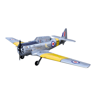
- Page 1 Instruction Manual Book SPECIFICATION 1 Wingspan : 1,830 mm 72.05 in. 1 Length : 1,250 mm 49.21 in. 1 Weight : 3.8 kg 8.36 lbs. Parts listing required (not included): 1 Radio : 06 channels. 1 Servo : 08 servos. 1 Engine : 61 2 stroke;...
- Page 2 AT.6-TEXAN Instruction Manual ITEM CODE: BH75. This instruction manual is designed to help you build a great flying aeroplane. Please read this manual thoroughly before starting assembly of your AT.6 TEXAN. Use the parts listing below to identify all parts.
-
Page 3: Safety Precaution
AT.6-TEXAN Instruction Manual ITEM CODE: BH75. Caution: this model is not a toy! SAFETY PRECAUTION. If you are a beginner to this type of powered + This is not a toy model, please ask an experienced model flyer + Be sure that no other flyers are using your for help and support. - Page 4 AT.6-TEXAN Instruction Manual ITEM CODE: BH75. Temporary pin to keep hinge centered. Assemble then apply drops of thin C/A to center of hinge,on both sides. INSTALLING THE AILERON - FLAP SERVO CONTROL HORN. 1.1 INSTALLING THE AILERON SERVO . 1. Install the rubber grommets and brass eyelets onto the aileron servo.
- Page 5 AT.6-TEXAN Instruction Manual ITEM CODE: BH75. Electric wire 5. Instal servo tray with aileron servo into the wing as same as picture below. 2x10mm. 3. Drill 1,5mm pilot holes through the block of wood for each of the four mounting screws provided with the servo.
- Page 6 AT.6-TEXAN Instruction Manual ITEM CODE: BH75. Install aileron control horn as same as picture below. Aileron control horn Aileron Remove covering Control horn of the aileron Repeat the procedure for the other wing half.
-
Page 7: Installing The Aileron Linkages
AT.6-TEXAN Instruction Manual ITEM CODE: BH75. 1.3.INSTALLING THE AILERON LINKAGES. Installing the aileron linkages as pictures below. M3 lock nut 2x10mm. 2.1 INSTALLING THE FLAP SERVO . 2.2INSTALLING THE FLAP CONTROL HORN. Nilon control clasp. M3 lock nut 3 x 40mm... - Page 8 AT.6-TEXAN Instruction Manual ITEM CODE: BH75. Control horn of the flap Repeat the procedure for the other wing half. 2.3INSTALLING THE FLAP LINKAGES. Installing the flap linkages as pictures below. Bottom of left wing. Aileron Flap...
- Page 9 AT.6-TEXAN Instruction Manual ITEM CODE: BH75. Bottom of right wing. Mark point Repeat the procedure for the other wing half. INSTALLING AIR RETRACTABLE LANDING GEAR. Bottom side AIR RETRACTS SYSTEM INSTALLATION. 3 x 15mm 3 x 15mm...
- Page 10 AT.6-TEXAN Instruction Manual ITEM CODE: BH75. 3 x 15mm Secure Secure 4 x 35mm...
- Page 11 AT.6-TEXAN Instruction Manual ITEM CODE: BH75. Bottom side Air tank Air supply Valve one way Right main gear wing Left main gear wing Top side Control Valve control valve Secure Valve control valve one way 3 way connector...
- Page 12 AT.6-TEXAN Instruction Manual ITEM CODE: BH75.
- Page 13 AT.6-TEXAN Instruction Manual ITEM CODE: BH75. Secure Right side...
-
Page 14: Wing Attachment
AT.6-TEXAN Instruction Manual ITEM CODE: BH75. *** Test fit the aluminium tube dihedral brace into each wing haft. The brace should slide in easily. If not, use 220 grit sand around the edges and ends of the brace until it fits prop- erly. -
Page 15: Installing The Engine Mount
AT.6-TEXAN Instruction Manual ITEM CODE: BH75. INSTALLING THE ENGINE MOUNT. See pictures below: 4 x 30mm 4 x 30mm Drill a hole 3mm diameter Top left side Secure Top side Drill a hole 2mm diameter Bottom side... -
Page 16: Installing The Stopper Assembly
AT.6-TEXAN Instruction Manual ITEM CODE: BH75. FUEL TANK. INSTALLING THE STOPPER ASSEMBLY 1 1) The stopper has been pre-assembled Silicon not included at the factory. Vent tube Fuel pick- up tube 1 2) Using a modeling knife, cut one length... -
Page 17: Installing The Engine
AT.6-TEXAN Instruction Manual ITEM CODE: BH75. Blow through one of the lines to ensure the fuel lines have not become kinked inside the fuel tank compartment. Air should flow through easily. 1 9) To secure the fuel tank in place, ap-... - Page 18 AT.6-TEXAN Instruction Manual ITEM CODE: BH75. Drill a hole 4mm diameter Secure Right side Left side Pushrod wire. COWLING. 1 1) Slide the fiberglass cowl over the en- gine and line up the back edge of the cowl with the marks you made on the fuselage.
- Page 19 AT.6-TEXAN Instruction Manual ITEM CODE: BH75. 1 2) While keeping the back edge of the Left side cowl flush with the marks, align the front of the cowl with the crankshaft of the engine. The front of the cowl should be positioned so the crankshaft is in nearly the middle of the cowl opening.
-
Page 20: Elevator Installation
AT.6-TEXAN Instruction Manual ITEM CODE: BH75. Connector. Throttle pushrod Servo arm. ELEVATOR INSTALLATION. After installing the adjustable metal con- SERVO INSTALLATION. nector apply a small drop of thin C/A to the bottom nut. This will prevent the con- 1. Install the rubber grommets and brass nector from loosening during flight. -
Page 21: Horizontal Stabilizer
AT.6-TEXAN Instruction Manual ITEM CODE: BH75. 1. Draw a center line onto the horizontal HORIZONTAL STABILIZER. stabilizer. Then slide the horizontal into the See pictures below: fuselage. Top side center line 2 Using a modeling knife, cut away the covering from the fuselage for the stabilizer and remove it. - Page 22 AT.6-TEXAN Instruction Manual ITEM CODE: BH75. 1 4. Remove the stabilizer. Using the lines you just drew as a guide, carefully remove the Epoxy glue covering from between them using a modeling knife. When cutting through the covering to remove it, cut with only enough pressure to only cut through the covering it’s self.
-
Page 23: Elevator Control Horn Installation
AT.6-TEXAN Instruction Manual ITEM CODE: BH75. ELEVATOR CONTROL HORN INSTALLATION. Elevator control horn install as same as the way of aileron control horn. Please see pic- tures below. 3 x 40mm. Nilon control clasp. M3 lock nut. Control horn of elevator. - Page 24 AT.6-TEXAN Instruction Manual ITEM CODE: BH75. R e m o v e covering C/A glue E l e v a t o r E l e v a t o r pushrod pushrod Bottom side Secure...
-
Page 25: Vertical Installation
AT.6-TEXAN Instruction Manual ITEM CODE: BH75. VERTICAL INSTALLATION. Rudder servo install as same as method of elevator servo. See picture below: Bend and cut after Secure Elevator servo Elevator pushrod... - Page 26 AT.6-TEXAN Instruction Manual ITEM CODE: BH75. Remove covering 1 1. Put the rudder into the fuselage as same as picture below. 2. Mark the shape of the vertical on the left and right side of the rudder on to the horizon- tal stabilizer using a felt-tip pen.
- Page 27 AT.6-TEXAN Instruction Manual ITEM CODE: BH75. Epoxy glue Cut the covering away from the slot. Temporary pin to keep hinge centered. Epoxy glue Assemble then apply drops of thin C/A to center of hinge,on both sides. 6. Using a modeling knife cut away the covering from the end of fuselage for the rud- der hinge.
-
Page 28: Rudder Control Horn Installa- Tion
AT.6-TEXAN Instruction Manual ITEM CODE: BH75. RUDDER CONTROL HORN INSTALLA- TION. Rudder control horn install as same as the way of aileron control horn. Please see pic- tures below. Remove covering 3mm x 40mm. M3 lock nut. Nilon control clasp... -
Page 29: Rudder Pushrod Installation
AT.6-TEXAN Instruction Manual ITEM CODE: BH75. RUDDER PUSHROD INSTALLATION. Remove covering C/A glue... -
Page 30: Mounting The Tail Wheel Bracket
AT.6-TEXAN Instruction Manual ITEM CODE: BH75. Elevator servo Throttle servo Rudder servo MOUNTING THE TAIL WHEEL BRACKET. 3x12mm 1 1. Set the tail wheel assembly in place on the plywood plate. The pivot point of the tail wheel wire should be even with the rud- der hinge line and the tail wheel bracket should be centered on the plywood plate. -
Page 31: Installing The Switch
AT.6-TEXAN Instruction Manual ITEM CODE: BH75. 1 3. Secure the tail wheel bracket in place using three 3mm x 12mm wood screws. Be careful not to overtighten the screws. 3x12mm INSTALLING THE SWITCH. 1 1) Cut out the switch hole using a modeling INSTALLING THE AIR TANK. - Page 32 AT.6-TEXAN Instruction Manual ITEM CODE: BH75. switch INSTALLING THE RECEIVER AND BATTERY. 1 1. Plug the servo leads and the switch lead into the receiver. You may want to plug an aileron extension into the receiver to make plugging in the aileron servo lead easier when you are installing the wing .
- Page 33 AT.6-TEXAN Instruction Manual ITEM CODE: BH75. See picture wing attach to fuselage. C/A glue Wing bolt. Installing the fuselage hatch as same as pic- ture below. Insert and secure...
- Page 34 AT.6-TEXAN Instruction Manual ITEM CODE: BH75. C/A glue C/A glue C/A glue Mark point...
-
Page 35: Control Throws
AT.6-TEXAN Instruction Manual ITEM CODE: BH75. CONTROL THROWS. BALANCING. 4 1) We highly recommend setting up a 1 1) It is critical that your airplane be bal- plane using the control throws listed. anced correctly. Improper balance will cause your plane to lose control and crash.
Need help?
Do you have a question about the AT.6-TEXAN and is the answer not in the manual?
Questions and answers