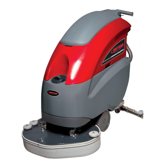
BETCO Stealth ASD26BT Operator And Parts Manual
26” automatic scrubber with traction drive
Hide thumbs
Also See for Stealth ASD26BT:
- Operator and parts manual (54 pages) ,
- Operator and parts manual (56 pages)
Table of Contents
Advertisement
Quick Links
Advertisement
Table of Contents

Subscribe to Our Youtube Channel
Related Manuals for BETCO Stealth ASD26BT


Summary of Contents for BETCO Stealth ASD26BT
- Page 1 E87026-00 E88064-00 STEALTH ASD26BT 26” Automatic Scrubber ™ with Traction Drive Operator and Parts Manual 1001 Brown Avenue • Toledo, Ohio 43607-0127 Customer Service: 888-GO-BETCO • Fax: 800-445-5056 • Technical Service: 877-856-5954 • www.betco.com...
-
Page 2: Table Of Contents
TABLE OF CONTENTS RECEIVING THE MACHINE........3 - 4 GENERAL SAFETY REGULATIONS ......... 5 MACHINE PREPARATION ........6 - 12 OPERATION ............13 - 14 TURNING OFF THE MACHINE ........15 DAILY MAINTENANCE ..........16 -17 WEEKLY MAINTENANCE ..........18 TROUBLESHOOTING ........... 19 BRUSH AND SELECTION USE........19 PARTS DIAGRAMS AND LISTINGS .......20 - 41 ELECTRICAL SYSTEM...........42 - 44 BATTERY CHECK CARD –... -
Page 3: Receiving The Machine
RECEIVING THE MACHINE Immediately check, when receiving the machine, that all the materials indicated on delivery documents have been received and also that the machine has not been damaged in transit. If it has been damaged, this damage must be immediately reported to the shipper and also to our customer’s service department. - Page 4 TECHNICAL DESCRIPTION Measurement Unit Stealth ASD26BT ™ Rated power HP (W) 1.7 (1260) Working width In (mm) 26 (660) Rear squeegee width In (mm) 37.3 (948) Work capacity ft2/h (m2/h) 31,970 (2970) Brush & Pad (diameter) in (mm) 13 (330) Brush RPM Brush pressure lb.
-
Page 5: General Safety Regulations
• Before using the machine make sure that all doors and covers are positioned as shown in this operating and maintenance manual. • When your BETCO machine is ready to be retired, the machine must be disposed of properly. It contain oils and electronic components. The machine was built using totally recyclable materials. -
Page 6: Machine Preparation
MACHINE PREPARATION 1. HANDLING THE PACKED MACHINE The machine is contained in specific packaging. It is not possible to place more than two packages on top of each other. The total weight is 253.5 lbs. (115 kg). The overall dimensions of the package are: A : 49.6 in (1260 mm) B : 28.4 in (720 mm) C : 65.4 in (1660 mm) - Page 7 Weight 97 lb. (44 kg) WARNING: Your charger must be set according to the type of bat- tery you install. Call BETCO customer service to ensure correct charger setting after replacement batteries are installed. • The batteries must be handled using lifting and transportation means suitable for the weight and dimensions.
- Page 8 MACHINE PREPARATION 5. BATTERY MAINTENANCE For maintenance and recharging, follow the instructions provided by the battery manufacturer. 6. BATTERY DISPOSAL When the battery reaches the end of its life, it must be disconnected by certi- fied professional, then lifted (using the handles and suitable lifting device) to remove it from the battery compartment.
- Page 9 MACHINE PREPARATION 9. CONNECTING THE BATTERY CONNECTOR Connect the battery connector (2) to the machine connector (1) 10. BATTERY INDICATOR The battery indicator uses LEDs and has 8 positions (7 yellow - charged batter- ies, and 1 red - run down batteries). WARNING: A few seconds after the red indicator light comes on, the brush motor turns off automatically.
- Page 10 MACHINE PREPARATION 11. INSTRUMENT PANEL COMPONENTS The instrument panel components are identified as follows: A. Paddles to activate brushes / traction (located beneath the grip) B. ON/OFF key switch C. Battery level / hour meter 12. REAR COMPONENTS The rear components are identified as follows: A.
- Page 11 MACHINE PREPARATION 15. ADJUSTING THE SQUEEGEE HEIGHT The height of the squeegee must be adjusted based on wear of the squeegee. To do this, turn the knob (2) counter clockwise to raise the squeegee, and clock- wise to lower it. Note: the right and left wheels must be adjusted to the same level, so the squeegee works parallel to the floor.
-
Page 12: Machine Preparation ........................................6
MACHINE PREPARATION 18. SOLUTION TANK Remove the front inlet cap and check the solution filter is correctly installed. Check the solution filter cover (beneath the tank) is correctly closed. 19. SOLUTION TANK • Fill the tank with clean water in the front fill location (1) or at the rear fill location (2) at a temperature not exceeding 120°F (50°C). -
Page 13: Operation
OPERATION 1. PREPARING TO WORK A. Connect the battery plug (1) to the machine plug B. Turn the key (1) of the main switch to the "ON" position (clockwise). The bat- tery charge level indicator lights will immediately come on. C. - Page 14 OPERATION 2. REVERSE MOVEMENTS To move in the reverse direction, push the switch levers (1) forward. WARNING: When making reverse movements, raise the squeegee. 3. OVERFLOW DEVICE The machine has a float in the filter basket that activates when the recovery tank is full and stops airflow into the vacuum.
-
Page 15: Turning Off The Machine
SHUTTING DOWN THE MACHINE 1. END OF WORK When shutting down the machine and before you perform any type of mainte- nance: A. Turn off the solution control valve using the handle (1) B. Raise the brush deck using the foot lever (2) C. -
Page 16: Daily Maintenance
DAILY MAINTENANCE 1. CLEANING THE RECOVERY TANK A. Raise the vacuum unit (1). B. Remove the drain hose (2) and empty the tank. C. Rinse the inside of the tank with water. D. Close the vacuum unit on the machine and replace the drain hose cap and drain hose. - Page 17 DAILY MAINTENANCE 4. CLEANING THE SQUEEGEE Ensure the squeegee is always clean, to improve drying results. To clean: A. Remove the squeegee vacuum hose from the squeegee shoe adapter. B. Remove the cotter pins that attach the pins of the squeegee shoe. C.
-
Page 18: Weekly Maintenance
WEEKLY MAINTENANCE 1. CLEANING THE SQUEEGEE HOSE Every week, or whenever vacuum seems to be unsatisfactory, check the squee- gee hose for obstructions. To clean: A. Remove the hose from the squeegee shoe adapter on the squeegee shoe. B. Remove the other end from the recovery tank. C. -
Page 19: Troubleshooting
TROUBLESHOOTING GUIDE INSUFFICIENT WATER ON THE PAD 1. Verify that the solution control valve – located beneath the symbol – (1) is turned on. 2. Verify that there is water in the solution tank. THE MACHINE DOES NOT CLEAN WELL 1. -
Page 20: Parts Diagrams And Listings
BRUSH DECK DIAGRAM... - Page 21 BRUSH DECK PARTS LISTING Item# Part # Description Qty. Item# Part # Description Qty. E20476 Tubing 8 ID x 12 OD x 250 L E83935 Wire Tie E20329 Tubing 8 ID x 12 OD x 300 L E86275 Barbed Elbow, 3/8" E20481 Fitting, Hose Barb 1/4"...
- Page 22 BRUSH DRIVE DIAGRAM...
- Page 23 BRUSH DRIVE PARTS LISTING Item# Part # Description Qty. Item# Part # Description Qty. E83547 Hex Bolt M6x16 Zinc E82424 Motor Pulley E85723 Idler Pulley E82772 Hex Bolt M6x20 Zinc E20428 Tensioner Bracket E82738 Brush Motor 24VDC 560W E20491 Tensioner Arm E83524 Bushing E81957...
- Page 24 BRUSH DECK LIFT DIAGRAM...
- Page 25 BRUSH DECK LIFT PARTS LISTING Item# Part # Description Qty. Item# Part # Description Qty. E88011 Hex Bolt, M10 x 30 Zinc E82689 Spring, 15x2x60mm Galv Extension E20219 Brush Deck Lift Arm Weldment E83852 Hex Nut, M6x5 E20220 Brush Deck Lift Arm Linkage E83656 Hex Nut, M8x6.5 Zinc E20062...
- Page 26 SQUEEGEE DIAGRAM 9, 29...
- Page 27 SQUEEGEE PARTS LISTING Item# Part # Description Qty. Item# Part # Description Qty. E82275 Pin, Adjustable Mounting M10 Zinc E82253 Bushing, Brass OD 11.95mm x ID 8.9mm x L 8.45mm 2 E82280 Pin, Fixed Mounting M10 Zinc E83802 Hex Bolt M8x30 Zinc E82707 Set Screw Hex Soc Flat End M6x40 SS E81834...
- Page 28 SQUEEGEE YOKE DIAGRAM 1.25 1.14 1.30 1.32 1.10 1.27 1.15 1.24 1.21 1.17 1.31 1.11 1.13 1.29 1.20 1.22 1.18 1.28 1.22 1.23 1.31 1.16 1.17 1.19 1.33 1.26 1.34 1.26 1.33 1.12...
- Page 29 SQUEEGEE YOKE PARTS LISTING Item# Part # Description Qty. Item# Part # Description Qty. 1.28 E83278 Flat Washer M6.5x24x2 Zinc E20623 Squeegee Yoke ASM E20010 Pivot Pin 1.29 E82774 Lock Washer, M6 Zinc E82389 Tie Rod, M6 Square Head Zinc 1.30 E88238 Flat Washer, M8x17x1.6 SS...
- Page 30 MAIN FRAME DIAGRAM 7.12 7.10 7.13 7.11 7.14...
- Page 31 MAIN FRAME PARTS LISTING Item# Part # Description Qty. Item# Part # Description Qty. E82772 Hex Bolt M6x20 Zinc E20003 Axle Shaft ASM E20478 Axle Shaft E81056 Spring E20482 Spacer E83974 Hex Bolt M6x30 Zinc E20081 Bearing Block E81917 Hex Bolt M8x20 Zinc E83923 Bearing E87285...
- Page 32 TANK ASSEMBLY DIAGRAM 4.11 4.10 19, 24...
- Page 33 TANK ASSEMBLY PARTS LISTING Item# Part # Description Qty. Item# Part # Description Qty. E82269 Barbed Fitting, 3/8 in. E88499 Hose, Vacuum E20004 Tubing 12 ID x 200 L E20185 E88288 Hose, Glass Reinforced 17 OD x 12 ID x 820 L E20201 Soltuion Tank E20228...
- Page 34 VACUUM UNIT DIAGRAM 2.19 2.27 2.11 2.13 2.30 2.26 2.29 2.14 2.23 2.18 2.17 2.15 2.10 2.16 2.24 2.22 2.28 2.12 2.31 2.25 2.32 2.26 2.20.2 2.21 2.20.1 2.20.3 2.20 2.20.4.2...
- Page 35 VACUUM UNIT PARTS LISTING Item# Part # Description Qty. Item# Part # Description Qty. 2.19 E20064 Support Bracket E20265 Plate E20066 Recovery Tank Cover ASM 2.20 E88291 Vacuum Motor 36VDC 550W E20305 Mounting Ring 2.20.1 E83897 Connector, Electrical Housing 30A E20652 Sound Deadening Foam 2.20.2...
- Page 36 SOLUTION CONTROL DIAGRAM...
- Page 37 SOLUTION CONTROL PARTS LISTING Item# Part # Description Qty. Item# Part # Description Qty. E83617 O-Ring, 14x2.5mm Buna-N E20004 Tubing 12 ID x 200 L E20530 Tubing 12 ID x 460 L E20098 Hex Bolt M8x18 Zinc E82693 Hose, 17 OD x 12 ID x L 420 E83838 Screw, Flat Hd M4x15 Zinc E82447...
- Page 38 HANDLEBAR DIAGRAM 2.18 2.11 2.15 2.20 2.17 2.21 2.13 2.16 2.21 2.10 2.14 2.19 2.12...
- Page 39 HANDLEBAR PARTS LISTING Item# Part # Description Qty. Item# Part # Description Qty. E20625 Electrical Control Panel ASM E82351 Key Switch Assembly w/Keys E83173 Contact, Key Switch E83836 Hex Bolt M5x16 Zinc E83316 Key Switch E20288 Soc Hd Cap Screw M8x30 Zinc E83316 Key Switch E20242...
- Page 40 ELECTRICAL COMPONENTS DIAGRAM...
- Page 41 ELECTRICAL COMPONENTS PARTS LISTING Item# Part # Description Qty. Item# Part # Description Qty. E20065 Bracket E20377 Rivet, M2.4x8 AL E20646 Chopper Card E20484 Fuse Block E83170 Fuse, 80 Amp E83628 Contactor 24VDC E83159 Relay 24VDC 20A E20448 Bracket E20097 Hex Bolt M8x40 SS E20129 E20248...
-
Page 42: Electrical System
ELECTRICAL DIAGRAM... - Page 43 ELECTRICAL LISTING Item# Part # Description Item# Part # Description E20619 SB175 Red Electrical Connector E82351 Key Switch E88293 Hour Meter E20619 SB175 Red Electrical Connector E20646 Chopper Card E83972 Fuse 30A fasten E83628 Contactor 24VDC E83159 Relay 24VDC 20A E83628 Contactor 24VDC E20368...
-
Page 44: Electrical Diagram
ELECTRICAL DIAGRAM VACUUM MOTOR ELECTRIC HARNESS INSPECTION 1. Verify the functionality of the variable speed control card. 2. If necessary adjust the variable speed control card as follows: • Lift up at least one of the traction wheels. • Remove the handlebar to gain access to the electric controls. •... -
Page 45: Battery Check Card - Hour Meter
BATTERY CHECK CARD – HOUR METER 1. Verify that when turning on the machine the battery check card has the following starting sequence: • Turning on of the LED which correspond to the set-up (red LED = “0”). • Turning on of all the LEDs (check of the lamps) •... -
Page 46: Brake Adjustment
BRAKE ADJUSTMENT 1. Adjust the brake pads on the wheels to lock the wheels when the brake lever reaches the third ratchet notch. 2. To adjust the pads: • Unscrew the M8 jam nut. • Adjust the pad. • Tighten the M8 jam nut. VACUUM SYSTEM INSPECTION 1. -
Page 47: Brush Adjustment
BRUSH ASSEMBLY ADJUSTMENT 1. Verify that when the foot lever is locked in the brush deck up position the micro switch is activated and the micro switch actuator has 0.5 mm of travel remaining. 2. If necessary adjust the micro switch as follows: •... -
Page 48: Squeegee Adjustment
SQUEEGEE ADJUSTMENT 1. Adjust the inclination adjuster of the squeegee assembly until the squeegee blade has a uniform deflection along its entire length. 2. Adjust the height of the squeegee wheels using the knob such that the squee- gee blade has an inclination between 30 and 45 degrees. 3. -
Page 49: Check List
CHECK LIST Functional check of the machine Check the functionality of switches and warning lamps. Check the functionality of the switch lever. Check the functionality of the brush deck. Check the functionality of the brush motor. Check the functionality of the solenoid valve. Check the functionality of the vacuum motor. -
Page 50: Maintenance Schedule
MAINTENANCE SCHEDULE RECOMMENDED SERVICE INTERVALS Stealth ASD26BT (HOURS) 750 1,000 Machine components Suggested replacement DAILY BATTERIES Check water level and add if necessary DAILY Check cleanless of machine battery tray ELECTRIC Check state of power contactors and fuses Check state of electric cables crossing... -
Page 51: Wear Items
WEAR ITEMS Stealth ASD26BT ™ PART DESCRIPTION NUMBER E81668 Pad Holder E81681 General Purpose 13" Scrub Brush E82850 Medium Duty 13" Brush, .6MM Tuft E82851 Heavy Duty 13" Brush, .9MM Tuft E82852 Tynex 13" Brush, 1.0MM Tuft E86143 Splash Guard E81835 Squeegee Blade, Polyurethane 38 1/4"... -
Page 52: Warranty
Service Distributor. If the original part is returned within the warranty policy period from date of delivery for inspection by Betco and is found to be defective the owner will be credited for the cost of replacement parts plus shipping and handling.
Need help?
Do you have a question about the Stealth ASD26BT and is the answer not in the manual?
Questions and answers