Hunter Stoves HAWK Installation And Servicing Instructions
Hide thumbs
Also See for HAWK:
- User instructions (5 pages) ,
- Installation and servicing instructions (16 pages) ,
- User instructions (6 pages)
Table of Contents
Advertisement
Quick Links
Download this manual
See also:
Instructions for Using
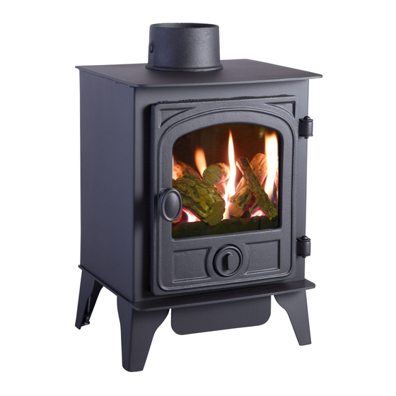
HAWK
GAS STOVE
Installation and Servicing
Instructions
Please leave this instruction booklet with the user after the installation is
complete. Leave the system ready for operation and instruct the user in the
correct use of the appliance and operation of its controls.
Please refer to the appliance data plate for the specific model type.
Revision D 30/08/2012
Advertisement
Table of Contents

Subscribe to Our Youtube Channel
Related Manuals for Hunter Stoves HAWK


Summary of Contents for Hunter Stoves HAWK
- Page 1 HAWK GAS STOVE Installation and Servicing Instructions Please leave this instruction booklet with the user after the installation is complete. Leave the system ready for operation and instruct the user in the correct use of the appliance and operation of its controls.
-
Page 2: Table Of Contents
Contents TECHNICAL DATA...........3 ....................3 TOVE IMENSIONS INSTALLING THE APPLIANCE ....4 ..................4 INSTALLATION NOTES ....................6 RRANGEMENT (GB O ) ..............6 DDITIONAL ENTING ..................7 PENING THE TOVE ..................7 UPPLY ONNECTIONS ..................8 ESTING UPPLY RESSURE INSTALLATION OF THE FIRE-BED INTO THE STOVE ............8 FIRE-BED ARRANGEMENT ............... -
Page 3: Technical Data
TECHNICAL DATA NATURAL GAS Nominal Gas Pressure 20mBar Supply Gas Type/Category G20/I Jet Type/Size 82/260 Heat Input (Gross) Full 4.7kW 3.5kW Gas Flow Rate (m Full 0.42 m Class Efficiency Class Countries of Destination GB & IE Only Stove Dimensions Diagram 1... -
Page 4: Installing The Appliance
INSTALLING THE APPLIANCE Pre-installation notes 1. Check the stove data plate to establish the gas type required. The data plate can be found bolted to the inside of the door. Before installation check that the local distribution conditions, nature of the gas and pressure, and adjustment of the application are compatible. - Page 5 Diagram 2 IMPORTANT NOTE! Adequate clearance must be given between the appliance and the walls so that a satisfactory spillage test can be performed as detailed on page 16. MINIMUM CLEARANCE DISTANCES TO: DIMENSION COMBUSTIBLE NON-COMBUSTIBLE DESCRIPTION MATERIAL MATERIAL Side of stove to wall 150mm 100mm Top of stove to underside of...
-
Page 6: Flue Arrangement
The chimney or flue system that is to be fitted to the Hawk gas stove must comply with the current rules in force. -
Page 7: Opening The Stove Door
Opening the Stove Door NOTE! This appliance must never be used with the door open or removed. Before gaining access to the burner tray, first make sure that the stove is switched off and is cold. Now the cast iron door can be opened, this is secured in place by one fixing bolt. Firstly remove the door handle by turning anticlockwise. -
Page 8: Testing Supply Pressure
HANDLE HOT COALS OR LOGS WITH BARE HANDS AND NEVER PLACE HOT COALS OR LOGS ON OR NEAR COMBUSTIBLE SURFACES. NO RESPONSIBILITY FOR ANY INJURY HOWEVER CAUSED WHILST HANDLING HOT COALS, LOGS OR CERAMICS CAN BE ACCEPTED BY HUNTER STOVES LTD. -
Page 9: Fire-Bed Arrangement
FIRE-BED ARRANGEMENT ITTING THE ERAMIC ATRIX Cut-out in Ceramic Place the ceramic matrix onto the tray top, making sure that the cut-outs in both of the front bottom corners of the ceramic line up with the corresponding matrix positioning brackets on the tray top. -
Page 10: Section A - Fitting The Loose Ceramic Coals
Section A - Fitting the Loose Ceramic Coals HOULD 5 x Small Ceramic Coals 4 x Medium Ceramic Coals 2 x Large Diamond Ceramic Coals The first coals to be placed are the two ‘Diamond’ shaped coals. These should be placed in diamond shaped cut-outs as shown in diagram 9. -
Page 12: Section B - Fitting The Loose Ceramic Logs
Section B - Fitting the Loose Ceramic Logs HOULD 1 x Y-Shaped Ceramic Log 1 x Small Branch Log 1 x 152x38 Single Branch 2 x 75x38 Very Small Branch Log 1 x Twig The first log to be placed is the small branch log. - Page 13 The next to be placed is the single branch log that sits in a groove to the right of the ‘Y’ shaped log behind the third flame port hole in the matrix. The top of the log sits in the cut-out that is located on the top edge of the back of the ceramic matrix, as shown in...
- Page 14 The next log is the second very small branch log that sits on the short arm of the ‘Y’ shaped log. The top of this sits in the cut-out on the rear upright at the back of the matrix. This is shown in diagram 16.
-
Page 15: Fitting The Canopy - (Optional )
ANOPY PTIONAL There is an optional canopy available for the Hunter Hawk gas stove. The canopy can be simply slid into place on the top plate of the stove body (Shown in diagram 18), making sure that the two welded tabs (located either side of the canopy) fit under the top plate. -
Page 16: Test For Spillage
The TTB MUST NOT be removed or ‘bridged out’ for any reason and only genuine Hunter Stoves replacements should be used. Nuisance shut down may occur if the stove is not installed in accordance with the clearance distances set out in page 5. -
Page 17: Servicing Instructions
It must be understood that any recommendations made here are in addition to the standard servicing procedures used by the servicing engineer. 1. A GAS SAFE registered fitter using only original Hunter Stoves parts should carry out servicing. 1. Open the stove door as described on Page 7. -
Page 18: Spares List
SPARES LIST PART DESCRIPTION PART NUMBER TTB Set TTB Switch HG06/200 TTB Leads HG06/201 Natural Gas Burner Injector HGH/028 Control Valve HGH/045 Glass Panel (D Type Door) HCR06/058 Glass Panel (Standard Door) HCR06/039 Glass Clip + Screw HHR08/046 Door Rope Kit (D Type Door) SCPHKDRSK Door Rope Kit (Standard Door) SCPHKRSK...
Need help?
Do you have a question about the HAWK and is the answer not in the manual?
Questions and answers