Table of Contents
Advertisement
Quick Links
Advertisement
Table of Contents

Related Manuals for IEI Technology IOVU-210AR-RK39


Summary of Contents for IEI Technology IOVU-210AR-RK39
- Page 1 IOVU-210AR-RK39 Panel PC MODEL: IOVU-210AR-RK39 10.1" RISC-Based Panel PC with P-CAP Touchscreen, Rockchip RK3399 On-board SoC, Wi-Fi, Bluetooth, Camera, USB, SOS Key, GbE with PoE, Android 7.1, RoHS Compliant User Manual Page i Rev. 1.00 – November 8, 2018...
- Page 2 IOVU-210AR-RK39 Panel PC Revision Date Version Changes November 8, 2018 1.00 Initial release Page ii...
- Page 3 IOVU-210AR-RK39 Panel PC Copyright COPYRIGHT NOTICE The information in this document is subject to change without prior notice in order to improve reliability, design and function and does not represent a commitment on the part of the manufacturer. In no event will the manufacturer be liable for direct, indirect, special, incidental, or consequential damages arising out of the use or inability to use the product or documentation, even if advised of the possibility of such damages.
- Page 4 IOVU-210AR-RK39 Panel PC Manual Conventions WARNING Warnings appear where overlooked details may cause damage to the equipment or result in personal injury. Warnings should be taken seriously. CAUTION Cautionary messages should be heeded to help reduce the chance of losing data or damaging the product.
-
Page 5: Table Of Contents
IOVU-210AR-RK39 Panel PC Table of Contents 1 INTRODUCTION ......................1 1.1 O ........................2 VERVIEW 1.2 F ........................2 EATURES 1.3 F ......................3 RONT ANEL 1.4 R ....................... 4 ANEL 1.5 S .................... 5 YSTEM PECIFICATIONS 1.6 D ....................... 7 IMENSIONS 2 UNPACKING ......................... - Page 6 IOVU-210AR-RK39 Panel PC 3.4.2.1 In-Wall Mounting Box Dimensions ............23 3.5 P ................... 24 OWER ROCEDURE 3.6 A ....................25 VAILABLE RIVERS 3.6.1 Driver Download ..................... 25 3.7 S ................... 27 YSTEM AINTENANCE 4 ANDROID OS ......................28 4.1 H ......................
- Page 7 IOVU-210AR-RK39 Panel PC List of Figures Figure 1-1: IOVU-210AR-RK39 Panel PC ..................2 Figure 1-2: Front Panel ........................3 Figure 1-3: Rear Panel ........................4 Figure 1-4: Dimensions (Unit: mm) ....................7 Figure 3-1: microSD Card Slot ....................14 Figure 3-2: LAN2 Connector ......................16 Figure 3-3: USB Connectors ......................
- Page 8 IOVU-210AR-RK39 Panel PC List of Tables Table 1-1: Technical Specifications ....................6 Table 2-1: Packing List ......................... 10 Table 2-2: Optional Item ....................... 10 Table 3-1: DIO Connector (DIO2, DIO3) Pinouts ................ 13 Table 3-2: DIO Terminal Block (DIO1) Pinouts ................13 Table 3-3: I C Connector (I2C) Pinouts ..................
-
Page 9: Introduction
IOVU-210AR-RK39 Panel PC Chapter Introduction Page 1... -
Page 10: Overview
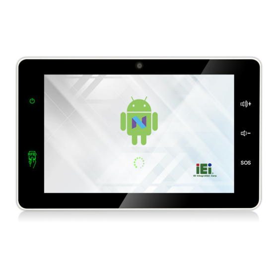
1.1 Overview Figure 1-1: IOVU-210AR-RK39 Panel PC The IOVU-210AR-RK39 is a 10.1" RISC-based panel PC with Android 7.1 OS. At the heart of the system is the Rockchip RK3399 on-board SoC, offering low power in a powerful package. The IOVU-210AR-RK39 provides rich input capabilities utilizing the projected capacitive touchscreen. -
Page 11: Front Panel
Android 7.1 OS pre-installed RoHS compliant 1.3 Front Panel The front panel of the IOVU-210AR-RK39 contains a 10.1" LCD with projected capacitive touchscreen, 5-megapixel camera, an SOS key, two volume keys, a power indicator and an RFID indicator. Figure 1-2: Front Panel The states of the LED indicators located on the front panel are listed below. -
Page 12: Rear Panel
IOVU-210AR-RK39 Panel PC 1.4 Rear Panel The rear panel contains several I/O interfaces as shown below. The detailed information of each connector is listed in Section 3.3. Figure 1-3: Rear Panel NOTE: When both DC-in and PoE are connected to the device, the connection with higher voltage will be the main power source. -
Page 13: System Specifications
IOVU-210AR-RK39 Panel PC 1.5 System Specifications The IOVU-210AR-RK39 technical specifications are listed below. System Rockchip RK3399 on-board SoC (dual-core Cortex-A72 + quad-core Cortex-A53, 64-bit) Memory 2 GB 1866 MHz LPDDR3L on-board memory Storage 16 GB eMMC NAND flash One microSD card slot (rear panel) Audio 2 x Speaker (1.5 W) -
Page 14: Table 1-1: Technical Specifications
IOVU-210AR-RK39 Panel PC Physical Character Construction Material PC+ABS plastic Color White Mounting Wall mounting, in-wall mounting Dimensions (W x H x D) 282.5 mm x 176.4 mm x 26.8 mm Operation Temperature -10°C ~ 50°C (14°F ~ 122°F) with air flow Storage Temperature -20°C ~ 60°C (-4°F ~ 140°F) -
Page 15: Dimensions
IOVU-210AR-RK39 Panel PC 1.6 Dimensions The dimensions of the IOVU-210AR-RK39 are shown below. Figure 1-4: Dimensions (Unit: mm) Page 7... -
Page 16: Unpacking
IOVU-210AR-RK39 Panel PC Chapter Unpacking Page 8... -
Page 17: Packing List
If any of the components listed in the checklist below are missing, do not proceed with the installation. Contact the IEI reseller or vendor the IOVU-210AR-RK39 was purchased from or contact an IEI sales representative directly by sending an email to sales@ieiworld.com. -
Page 18: Optional Item
IOVU-210AR-RK39 Panel PC Quantity Item Image Wall mount bracket M4*6 screw for wall mounting M2.5*4 screw for wall mounting 4-pin terminal block 6-pin terminal block Table 2-1: Packing List 2.2 Optional Item The following is optional component which may be separately purchased:... -
Page 19: Installation
IOVU-210AR-RK39 Panel PC Chapter Installation Page 11... -
Page 20: Anti-Static Precautions
IOVU-210AR-RK39 and severe injury to the user. Electrostatic discharge (ESD) can cause serious damage to electronic components, including the IOVU-210AR-RK39. Dry climates are especially susceptible to ESD. It is therefore critical that whenever the IOVU-210AR-RK39 is accessed internally, or any other electrical component is handled, the following anti-static precautions are strictly adhered to. -
Page 21: External I/O Connectors
3.3 External I/O Connectors This section provides an overview of the external I/O connectors of the IOVU-210AR-RK39. 3.3.1 Digital I/O Connectors The IOVU-210AR-RK39 has two digital I/O connectors in Grove interface. The pinouts are shown below. Description DIO_3V3 DIO_D5/D7... -
Page 22: I 2 C Connectors
IOVU-210AR-RK39 Panel PC 3.3.3 I C Connectors The IOVU-210AR-RK39 has three I C connectors in Grove interface. The pinouts are shown below. Description IOT_3V3 SDA1_3V3 SCL1_3V3 Table 3-3: I C Connector (I2C) Pinouts 3.3.4 microSD Card Slot The system comes with a push-push microSD card slot for installation of a microSD card. -
Page 23: Lan Connectors
IOVU-210AR-RK39 Panel PC 3.3.5 RJ-45 LAN Connectors There are two RJ-45 LAN connectors that allow connection to external network, and the LAN1 connector also supports PoE function. 3.3.5.1 LAN1 Connector with PoE The LAN1 connector enables connection to an external network and supports PoE. The LAN1 connector pinouts are shown below. -
Page 24: Rs-232 Serial Interface
On: Linked Orange 1000 Mbps Flashing: Activity Table 3-6: LAN2 Ethernet Connector LEDs 3.3.6 RS-232 Serial Interface The IOVU-210AR-RK39 has one RS-232 connector in Grove interface. The pinouts are shown below. Description VIO_3V3 RS232_TXD1 RS232_RXD1 Table 3-7: RS-232 Connector (UART2) Pinouts... -
Page 25: Rs-232/422/485 Serial Interface
IOVU-210AR-RK39 Panel PC 3.3.7 RS-232/422/485 Serial Interface The system has a 4-pin RS-232/422/485 terminal block. Its pinouts are shown below. RS-232 RS-422 RS-485 DATA- DATA+ Table 3-8: RS-232/422/485 Terminal Block (UART1) Pinouts 3.3.8 USB Connectors The external USB Series "A" receptacle connectors provide easier and quicker access to external USB devices. -
Page 26: Mounting The System
IOVU-210AR-RK39 Panel PC 3.4 Mounting the System 3.4.1 Wall Mounting To mount the IOVU-210AR-RK39 onto a wall, please follow the steps below. Step 1: Select a location on the wall for the wall-mounting bracket. Carefully mark the locations of the screw holes of the wall mounting bracket on the mounting area. -
Page 27: Figure 3-5: Secure Mounting Screws
IOVU-210AR-RK39 Panel PC Figure 3-5: Secure Mounting Screws Step 4: Align the mounting holes on the rear of the panel PC with the mounting screws. Step 5: Carefully attach the panel PC to the mounting screws and gently pull the panel PC downwards until the panel PC rests securely on screws. -
Page 28: Wall Mount Bracket Dimensions
The dimensions of the wall mount bracket shipped with the system are shown below. Figure 3-7: Wall Mount Bracket Dimensions (Unit: mm) 3.4.2 In-Wall Mounting To mount the IOVU-210AR-RK39 into a wall using the optional in-wall mounting box, please follow the steps below. Step 1: When constructing the building, leave a section from the wall that corresponds to the dimensions of the in-wall mounting box. -
Page 29: Figure 3-8: Drill Holes For Securing In-Wall Mounting Box
IOVU-210AR-RK39 Panel PC Figure 3-8: Drill Holes for Securing In-Wall Mounting Box Step 3: Secure the mounting bracket to the in-wall mounting box by inserting the retention screws into the four pilot holes and tightening them (Figure 3-9 Step 4:... -
Page 30: Figure 3-9: Secure Mounting Screws
IOVU-210AR-RK39 Panel PC Figure 3-9: Secure Mounting Screws Step 6: Align the mounting holes on the rear of the panel PC with the bracket mounting screws. Step 7: Carefully attach the panel PC to the mounting screws and gently pull the panel PC downwards until the panel PC rests securely on screws. -
Page 31: In-Wall Mounting Box Dimensions
IOVU-210AR-RK39 Panel PC 3.4.2.1 In-Wall Mounting Box Dimensions The dimensions of the optional in-wall mounting box are shown below. Figure 3-11: In-Wall Mounting Box Dimensions (Unit: mm) Page 23... -
Page 32: Power-On Procedure
The IOVU-210AR-RK39 supports 9 V ~ 30 V DC power input. To power-on, connect the IOVU-210AR-RK39 power input jack to a power source. Once connected, the system will automatically turn on and the power LED on the front panel will light up in green. -
Page 33: Available Drivers
IOVU-210AR-RK39 Panel PC 3.6 Available Drivers All the drivers for the IOVU-210AR-RK39 are available on IEI Resource Download Center (https://download.ieiworld.com). Type IOVU-210AR-RK39 and press Enter to find all the relevant software, utilities, and documentation. Figure 3-13: IEI Resource Download Center 3.6.1 Driver Download... - Page 34 IOVU-210AR-RK39 Panel PC Step 3: Click the driver file name on the page and you will be prompted with the following window. You can download the entire ISO file ( ), or click the small arrow to find an individual driver and click the file name to download (...
-
Page 35: System Maintenance
IOVU-210AR-RK39 Panel PC 3.7 System Maintenance If the components of the IOVU-210AR-RK39 fail, they must be replaced. Please contact the system reseller or vendor to purchase the replacement parts. NOTE: A user cannot replace a motherboard. If the motherboard fails it must be shipped back to IEI to be replaced. -
Page 36: Android Os
IOVU-210AR-RK39 Panel PC Chapter Android OS Page 28... -
Page 37: Home Screen
IOVU-210AR-RK39 Panel PC The IOVU-210AR-RK39 comes with Android OS pre-installed. This chapter introduces the user interface and basic functions of Android OS installed in the IOVU-210AR-RK39. 4.1 Home Screen Android OS supports multiple home screens allowing users to customize the screen with widgets, apps and shortcuts. -
Page 38: Switching Between Home Screens
IOVU-210AR-RK39 Panel PC 4.1.2 Switching between Home Screens Swipe right or left to switch between home screens. Figure 4-2: Multiple Home Screens 4.1.3 Favorites Tray The Favorites tray at the bottom of each home screen allows users to keep the most important or frequently used shortcuts. -
Page 39: Adding Shortcuts
IOVU-210AR-RK39 Panel PC 4.1.4 Adding Shortcuts To add app or widget shortcuts on the home screen, follow the steps below. Step 1: To add an app shortcut, tap the up arrow on the home screen to access the All Apps page. -
Page 40: Figure 4-4: All Apps/Widgets Page
IOVU-210AR-RK39 Panel PC Step 2: Touch and hold an app icon or a widget, and drag it to the home screen. Figure 4-4: All Apps/WIDGETS Page Page 32... -
Page 41: Arranging The Home Screen
IOVU-210AR-RK39 Panel PC 4.1.5 Arranging the Home Screen The items on the home screen can be moved and deleted. Touch and hold an item on the home screen and drag it where you want. To trash the item on the screen, drag it to the Remove icon. -
Page 42: Navigation Buttons
IOVU-210AR-RK39 Panel PC 4.2 Navigation Buttons The navigation buttons shown in Figure 4-8 can always be found at the bottom of every screen. Figure 4-6: Navigation Buttons Buttons Description Tap to turn the volume down. Tap to return to the previous screen. -
Page 43: Status Bar
IOVU-210AR-RK39 Panel PC 4.3 Status Bar The status bar on the top of the screen (Figure 4-9) displays system status, such as battery level or signal strength. Figure 4-7: Status Bar Swipe down from the status bar to view notification and status details (Figure 4-10). -
Page 44: Figure 4-8: Notification List And System Status
IOVU-210AR-RK39 Panel PC Figure 4-8: Notification List and System Status Page 36... -
Page 45: A Regulatory Compliance
IOVU-210AR-RK39 Panel PC Appendix Regulatory Compliance Page 37... - Page 46 IOVU-210AR-RK39 Panel PC DECLARATION OF CONFORMITY This equipment is in conformity with the following EU directives: EMC Directive 2014/30/EU Low-Voltage Directive 2014/35/EU RoHS II Directive 2011/65/EU If the user modifies and/or install other devices in the equipment, the CE conformity declaration may no longer apply.
- Page 47 IOVU-210AR-RK39 Panel PC Español [Spanish] IEI Integration Corp declara que el equipo cumple con los requisitos esenciales y cualesquiera otras disposiciones aplicables o exigibles de la Directiva 1999/5/CE. Ελληνική [Greek] IEI Integration Corp ΔΗΛΩΝΕΙ ΟΤΙ ΕΞΟΠΛΙΣΜΟΣ ΣΥΜΜΟΡΦΩΝΕΤΑΙ ΠΡΟΣ ΤΙΣ ΟΥΣΙΩΔΕΙΣ ΑΠΑΙΤΗΣΕΙΣ ΚΑΙ ΤΙΣ ΛΟΙΠΕΣ ΣΧΕΤΙΚΕΣ ΔΙΑΤΑΞΕΙΣ ΤΗΣ ΟΔΗΓΙΑΣ...
- Page 48 IOVU-210AR-RK39 Panel PC Româna [Romanian] IEI Integration Corp declară că acest echipament este in conformitate cu cerinţele esenţiale şi cu celelalte prevederi relevante ale Directivei 1999/5/CE. Slovensko [Slovenian] IEI Integration Corp izjavlja, da je ta opreme v skladu z bistvenimi zahtevami in ostalimi relevantnimi določili direktive 1999/5/ES.
- Page 49 IOVU-210AR-RK39 Panel PC FCC WARNING This equipment complies with Part 15 of the FCC Rules. Operation is subject to the following two conditions: This device may not cause harmful interference, and This device must accept any interference received, including interference that may cause undesired operation.
-
Page 50: B Safety Precautions
IOVU-210AR-RK39 Panel PC Appendix Safety Precautions Page 42... -
Page 51: Safety Precautions
Do not apply voltage levels that exceed the specified voltage range. Doing so may cause fire and/or an electrical shock. Electric shocks can occur if the IOVU-210AR-RK39 chassis is opened when the IOVU-210AR-RK39 is running. Do not drop or insert any objects into the ventilation openings of the IOVU-210AR-RK39. -
Page 52: Anti-Static Precautions
Electrostatic discharge (ESD) can cause serious damage to electronic components, including the IOVU-210AR-RK39. Dry climates are especially susceptible to ESD. It is therefore critical that whenever the IOVU-210AR-RK39 is opened and any of the electrical components are handled, the following anti-static precautions are strictly adhered to. -
Page 53: Product Disposal
Please follow the national guidelines for electrical and electronic product disposal. B.2 Maintenance and Cleaning Precautions When maintaining or cleaning the IOVU-210AR-RK39, please follow the guidelines below. B.2.1 Maintenance and Cleaning Prior to cleaning any part or component of the IOVU-210AR-RK39, please read the details below. Page 45... -
Page 54: Cleaning Tools
Some components in the IOVU-210AR-RK39 may only be cleaned using a product specifically designed for the purpose. In such case, the product will be explicitly mentioned in the cleaning tips. Below is a list of items to use when cleaning the IOVU-210AR-RK39. ... -
Page 55: C Hazardous Materials Disclosure
IOVU-210AR-RK39 Panel PC Appendix Hazardous Materials Disclosure Page 47... - Page 56 IOVU-210AR-RK39 Panel PC The details provided in this appendix are to ensure that the product is compliant with the Peoples Republic of China (China) RoHS standards. The table below acknowledges the presences of small quantities of certain materials in the product, and is applicable to China RoHS only.
- Page 57 IOVU-210AR-RK39 Panel PC 此附件旨在确保本产品符合中国 RoHS 标准。以下表格标示此产品中某有毒物质的含量符 合中国 RoHS 标准规定的限量要求。 本产品上会附有”环境友好使用期限”的标签,此期限是估算这些物质”不会有泄漏或突变”的 年限。本产品可能包含有较短的环境友好使用期限的可替换元件,像是电池或灯管,这些元 件将会单独标示出来。 部件名称 有毒有害物质或元素 铅 汞 镉 六价铬 多溴联苯 多溴二苯醚 (Pb) (Hg) (Cd) (CR(VI)) (PBB) (PBDE) 壳体 显示 印刷电路板 金属螺帽 电缆组装 风扇组装 电力供应组装 电池 O: 表示该有毒有害物质在该部件所有物质材料中的含量均在 SJ/T11363-2006 (现由 GB/T 26572-2011 取代) 标准规定的限量要求以下。...
Need help?
Do you have a question about the IOVU-210AR-RK39 and is the answer not in the manual?
Questions and answers