Bromic Heating TUNGSTEN SMART-HEAT User Manual
Wireless on/off control
Hide thumbs
Also See for TUNGSTEN SMART-HEAT:
- Installation, instruction and service manual (27 pages) ,
- User manual (9 pages) ,
- Installation, instruction and service manual (26 pages)
Table of Contents

Related Manuals for Bromic Heating TUNGSTEN SMART-HEAT


Summary of Contents for Bromic Heating TUNGSTEN SMART-HEAT
- Page 1 TUNGSTEN SMART-HEAT™ WIRELESS ON/OFF CONTROL BY BROMIC USER MANUAL IMPORTANT READ THIS MANUAL CAREFULLY. SEE INSIDE COVER FOR IMPORTANT INFORMATION ABOUT THIS MANUAL.KEEP INSTRUCTION WITH APPLIANCE FOR FUTURE Version 1.3 REFERENCE. Doc. T645.01 TVRCL916A02F6...
- Page 2 Note: Bromic Heating reserves the right to make changes to specifications, parts, components and equipment without prior notification. This Installation, operation and service manual may not be reproduced in any form with prior written consent from Bromic Heating. Manufactured by Teleco Automation s.r.l. - Italy - www.telecoautomation.com...
- Page 3 CONTENTS IMPORTANT NOTES & WARNINGS PRODUCT OVERVIEW INSTALLATION & OPERATION TECHNICAL SPECIFICATIONS TROUBLESHOOTING WIRING DIAGRAM www.bromicheating.com...
- Page 4 IMPORTANT NOTES AND WARNINGS WARNING • This appliance must only be used on a 110 - 230 Volt AC Single Phase electricity supply. • Read all instructions before installing or using this heater • This controller is NOT intended to be installed on recreational vehicles and/or boats.
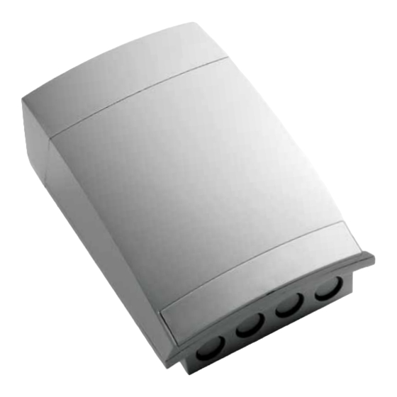
- Page 5 PRODUCT OVERVIEW & INSTALLATION 1 DESCRIPTION The Wireless ON/OFF control is for resistive and infrared heaters. The controller allows the power output of the heater to be turned on/off. The wireless control can be used with 110 - 230VAC supply voltages. 1.1 FEATURES •...
- Page 6 OPERATION 2.2.1 Setting relay function - ON/OFF ON/OFF Function Press the ‘SET’ button twice and hold it down until the ‘ON-OFF’ LED turns on. Wait until the LED turns off to confirm the memorisation of the data. Before starting select the output L1 or L2, using the switch (see picture at page 9). The following memorization/deletion will be applied only to the selected output.
- Page 7 OPERATION 2.2.5 Deleting all remotes Press the P2 button two times and hold the P2 button on the second time until the following sound sequence is heard. The will be one beep and then followed by a quick and intermittent sound. Continuous sound.
- Page 8 WIRING DIAGRAM hours LED minutes LED Box opening seconds LED ON/OFF LED Impulsive LED Switch for output selection Out L1 ↑ Out L2 ↓ Aerial connection N T T1 T2 Power EARTH supply OUT L1 OUT L2 (110/230Vac - 13A) (110/230Vac - 13A) (110/230Vac - 28A) 3000W max.
Need help?
Do you have a question about the TUNGSTEN SMART-HEAT and is the answer not in the manual?
Questions and answers