Bromic Heating TUNGSTEN SMART-HEAT Installation, Instruction And Service Manual
Hide thumbs
Also See for TUNGSTEN SMART-HEAT:
- Installation, instruction and service manual (26 pages) ,
- User manual (9 pages) ,
- Installation, instruction and service manual (26 pages)
Table of Contents
Advertisement
Quick Links
TUNGSTEN SMART-HEAT™
GAS HEATER
BY BROMIC
INSTALLATION, INSTRUCTION AND
SERVICE MANUAL
SUITABLE FOR GAS RADIANT HEATER MODELS:
TUNGSTEN 300 - BURNER AND TUNGSTEN 500 - BURNER
If you smell gas:
1.
Shut off gas to the appliance
2.
Extinguish any open flame
3.
If odor continues, keep away from the
appliance and immediately call your gas
supplier or fire department.
!
WARNING: For Outdoor or Amply
Ventilated area use and for NON
RESIDENTIAL INDOOR APPLICATION
Version 4.4 AUS
DANGER
!
WARNING
!
Do not store or use petrol or other flamable vapor and
liquids in the vicinity of this or any other appliance.
This appliance to be connected only to
reticulated gas & installed in accordance with AS/NZS
5601
!
WARNING: Improper installation,
adjustment, alteration, service or maintenance
can cause property damage, injury or death.
Read the installation, operating and
maintenance instructions thoroughly before
installing or servicing this equipment.
Advertisement
Table of Contents

Subscribe to Our Youtube Channel
Related Manuals for Bromic Heating TUNGSTEN SMART-HEAT


Summary of Contents for Bromic Heating TUNGSTEN SMART-HEAT
- Page 1 TUNGSTEN SMART-HEAT™ GAS HEATER BY BROMIC INSTALLATION, INSTRUCTION AND SERVICE MANUAL SUITABLE FOR GAS RADIANT HEATER MODELS: TUNGSTEN 300 - BURNER AND TUNGSTEN 500 - BURNER DANGER WARNING Do not store or use petrol or other flamable vapor and If you smell gas: liquids in the vicinity of this or any other appliance.
- Page 2 E: info@bromicheating.com W: www.bromic.com.au Note: Bromic Heating reserves the right to make changes to specifications, parts, components and equipment without prior notification. This Installation, operation and service manual may not be reproduced in any form with prior written consent from Bromic Heating. www.bromicheating.com...
-
Page 3: Table Of Contents
CONTENTS IMPORTANT NOTES & WARNINGS PRODUCT OVERVIEW PRODUCT DESCRIPTION SPECIFICATIONS GENERAL INFORMATION PRODUCT FEATURES INSTALLATION REQUIREMENTS GAS REQUIREMENTS INSTALLATION CLEARANCES INSTALLATION INSTRUCTIONS HEATER INSTALLATION INSTRUCTIONS GAS SUPPLY INSTALLATION POWER SUPPLY INSTALLATION LEAKAGE TEST HEAT DEFLECTOR INSTALLATION INSTRUCTIONS CEILING MOUNT POLE INSTALLATION INSTRUCTIONS OPERATING INSTRUCTIONS TURNING THE APPLIANCE ON TURNING THE APPLIANCE OFF... -
Page 4: Important Notes & Warnings
IMPORTANT NOTES AND WARNINGS of excessive abrasion or wear, or if the hose is damaged. WARNING • The replacement hose assembly must be AGA approved. • The hose assembly is not to be located in areas where • THIS APPLIANCE SHALL NOT BE INSTALLED OR USED the hose may be subject to accidental damage. -
Page 5: Product Overview
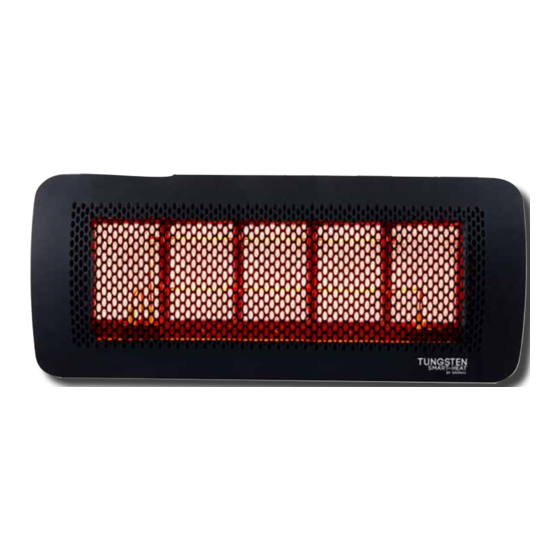
PRODUCT OVERVIEW PRODUCT DESCRIPTION The Tungsten Smart-Heat™ Gas Radiant Heaters are designed to provide effective outdoor heating to both commercial and residential premises whilst offering an appealing design. The heaters incorporate full function electronic controls, allowing them to be operated remotely from a conveniently located switch. -
Page 6: General Information
The approved inlet pressure to the appliance is 2.75KPA • natural ventilation • without stagnant areas Tungsten Smart-Heat Natural Gas Models: • where gas leakage and products of combustion are • Use Natural Gas Only rapidly dispersed by wind and natural convection •... -
Page 7: Installation Clearances
• In areas without sufficient clearances (refer below) Note: When installing with the Tungsten Smart-Heat Gas Note: When Installing with No protective cover, the following Heat Shield (Part No. 2620165 or 2620166) the following installation clearances shall apply: installation clearances Shall Apply: "... -
Page 8: Installation Instructions
Installation should be done by a qualified service person. CAUTION Please see specifications for the weight of the Heater. The installer of the Tungsten Smart-Heat Series Radiant Heaters must comply with all relevant State Occupational Health & Safety Regulations. 1. Mount Wall Bracket/Control Housing To Wall: •... - Page 9 INSTALLATION INSTRUCTIONS CONTINUED... 4. Attach Heater to Wall Bracket/Control Housing 5. Connect the AGA approved flexible connector to the Gas Valve Outlet Fitting • Remove Front Cover from Control Housing • Position heater and hose so that the gas hose and •...
- Page 10 INSTALLATION INSTRUCTIONS CONTINUED... 6. Insert Pivot Bolt • Insert Black Ignitor Cable directly into control box using 2.8mm spade connector, located on the side • Position Arm so that the rear hole’s on the mounting of the controller arm and Control Housing are in alignment •...
- Page 11 INSTALLATION INSTRUCTIONS CONTINUED... • Insert Earth Terminal over Earth Tab, attached to and carefully slide into place. Fix in place using the side of Wall Bracket Housing and marked with the retaining screw. symbol: Connect gas inlet fitting to mains gas supply in For White Rodger accordance with local gas installation code and gas supply installation section of manual.
-
Page 12: Gas Supply Installation
Gas Installation Codes. and flue gasses. Please Note: The inlet connection to the heater control box is a 3/8” SAE Tungsten Smart-Heat Gas do not have their own on/off Male WARNING Ensure that power socket is switched off before plugging in power cord. -
Page 13: Heat Deflector Installation Instructions
INSTALLATION INSTRUCTIONS CONTINUED... NOTE: Tungsten Smart-Heat Heating recommends running power and gas lines, to the heater, inside the pole to reduce visibility and likelihood of damage. HEAT-DEFLECTOR INSTALLATION 1. Assemble Heat Deflector following instructions supplied in the Heat Deflector carton. -
Page 14: Operating Instructions
Note: Avoid inhaling fumes emitted from the heater’s first troubleshooting section of this manual, or contact use. Smoke and odour from the burning of oils used in Tungsten Smart-Heat Heating Pty. Ltd for service manufacturing will appear. Both the smoke and odour will information. -
Page 15: Optimum Mounting Distance
IMPORTANT Replacement parts can be purchased to restore the heater to its original appearance from Tungsten Smart-Heat Heating Pty Do not apply any additional surface coating to the heater under any Ltd. (Refer to parts list in manual). circumstances. Use of additional coating other than those applied during manufacture could result in hazardous reactions such as toxic fumes or fires. -
Page 16: Honeywell Valve
OPERATION DATA - HONEYWELL CONTROL BOX CONTINUED... Directions for use Operation • Automatic controls are safety devices and shall not be At every start, the control unit proceeds to a self-checking opened. The manufacturer’s responsibility and guarantee of its own components. During the pre-purge or waiting are invalid if the control is unduly opened. -
Page 17: Operation Data - Brahma Control Box
Connect and disconnect the unit only after switching off Although the Brahma unit is capable of non volatile lockout, the power supply its configuration in the Tungsten Smart-Heat series heaters limits it to volatile lockout, i.e. the restart from this condition is •... -
Page 18: Dungs Gas Valve
OPERATION DATA - WHITE RODGER VALVE: The White Rodgers Gas Valve is a compact multi-functional TECHNICAL DATA control which incorporates an adjustable direct acting Max Working pressure 50 mbar pressure regulator. It is designed for quiet operation with Installation group Group 2 cushioned solenoid stops and operates on 220/240V. -
Page 19: Wiring Diagram
WIRING DIAGRAM - HONEYWELL CONTROL, HONEYWELL GAS VALVE ELECTRICAL DIAGRAM SEE INSTRUCTION MANUAL FOR DETAILS ON HOW TO CONNECT THE ELECTRICAL COMPONENTS. Ionisation Ionisation Ignition + Brown 230 V Red 230 V Blue Blue HONEYWELL White Black Yellow/Green Note: If any of the original wire as supplied with the heater must be replaced, it must be replaced with 18AWG, 90ºC type UL approved wire or its equivalent. - Page 20 WIRING DIAGRAM ELECTRICAL DIAGRAM SEE INSTRUCTION MANUAL FOR DETAILS ON HOW TO CONNECT THE ELECTRICAL COMPONENTS. Gas Valve Blue Ignition + Ionisation Ionisation Orange Blue Purple Brown Black Brahma Control Box CE11U White Yellow/Green www.bromicheating.com...
- Page 21 REPLACEMENT PARTS White Rodger Honeywell www.bromicheating.com...
-
Page 22: Replacement Parts
HG095 Note: For more information on obtaining spare parts contact the place of purchase or BROMIC HEATING Head Office: 10 Phiney Place, Ingleburn, Sydney, NSW 2565 Australia T: 1300 276 642 (within Australia) or +61 2 9748 3900 (from overseas) F: +61 2 9748 4289 E: info@bromicheating.com W: www.bromic.com.au... -
Page 23: Post-Installation Report
FOR TUNGSTEN SMART-HEAT GAS RADIANT HEATERS AFTER HEATER INSTALLATION PLEASE PHOTOCOPY, COMPLETE, & SEND THIS REPORT BY: FAX TO (02) 9748 4289 or BY MAIL TO Bromic Heating Pty Ltd, 10 Phiney Place, Inglegurn NSW 2565Australia or SCAN AND EMAIL TO info@bromicheating.com Customer Business Name: Please fill in the relevant information or circle the... -
Page 24: Troubleshooting
TROUBLESHOOTING SYMPTOM POSSIBLE CAUSE CORRECTIVE ACTION Heater will not turn on 1. No power 1. Have authorized electrician check 2. No gas power supply 2. Have authorized gas fitter check gas supply Heater turns on, but then cycles on 1. Insufficient flame on ionisation rod and off 2. - Page 25 APPENDIX A www.bromicheating.com...
- Page 26 APPENDIX A CONTINUED... www.bromicheating.com...
- Page 27 APPENDIX A CONTINUED... www.bromicheating.com...
Need help?
Do you have a question about the TUNGSTEN SMART-HEAT and is the answer not in the manual?
Questions and answers