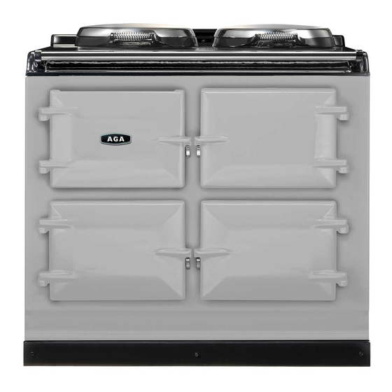
AGA TOTAL CONTROL TC3 Installation Manual
Hide thumbs
Also See for TOTAL CONTROL TC3:
- User manual (48 pages) ,
- User's manual & installation instructions (48 pages) ,
- User instruction (33 pages)
Table of Contents
Advertisement
Quick Links
AGA TOTAL CONTROL
Model No. - TC3
Installation
Guide
REMEMBER: when replacing a part on this appliance, use only spare parts that
you can be assured conform to the safety and performance specification that we
require. Do not use reconditioned or copy parts that have not been clearly
authorised by AGA.
PLEASE READ THESE INSTRUCTIONS BEFORE COMMENCING SITE SURVEY
OR INSTALLING THIS APPLIANCE.
For use in GB and IE
05/12 EINS 516350
Advertisement
Table of Contents

Summary of Contents for AGA TOTAL CONTROL TC3
- Page 1 AGA TOTAL CONTROL Model No. - TC3 Installation Guide REMEMBER: when replacing a part on this appliance, use only spare parts that you can be assured conform to the safety and performance specification that we require. Do not use reconditioned or copy parts that have not been clearly authorised by AGA.
-
Page 2: Table Of Contents
CONTENTS SECTION PAGE HEALTH AND SAFETY INSTALLATION REQUIREMENTS DELIVERY REQUIREMENTS APPLIANCE DIMENSIONS CLEARANCES MAINS CABLE ROUTING VENT PIPE CONNECTION OVEN VENTING SYSTEM POWER SUPPLY WIRING DIAGRAM HANDRAIL CONNECTION AGA TC3 POST INSTALLATION CHECKLIST... -
Page 3: Health And Safety
Any alteration that is not approved by AGA could invalidate the approval of the appliance, operation of the warranty and could also affect your statutory rights. In the interests of safety and effective use, please read the following before using your new AGA appliance. -
Page 4: Appliance Dimensions
10mm beyond the figures quoted above. This allows safe margin to take into account the natural dimensional variations found in major castings. In particular the width across the appliance recess could be critical. APPLIANCE WEIGHT Model: AGA Total Control (TC3) - 370kg... -
Page 5: Clearances
It is essential that the base or hearth on which the cooker stands should be level and be capable of supporting the total weight of the appliance. The base of the built-in AGA plinth must be level and sit above finished floor height for service access. -
Page 6: Mains Cable Routing
MAINS CABLE ROUTING MAINS CABLE FED FROM CONTROL TRAY LEFT OR RIGHT EXIT THROUGH DUCTING DEPENDENT UPON POSITION OF SUPPLY SOCKET Fig. 2 DESN 516103 THE MAINS SUPPLY CONNECT POINT MUST BE WITHIN THE ZONES SHOWN Fig. 2A DESN 516105... -
Page 7: Vent Pipe Connection
VENT PIPE CONNECTION Fig. 3 DESN 516356 A The appliance is shown with the oven venting from the RH side. To gain access remove rear panel (6 screws). It can also be vented from the LH side, by rotating the copper elbow 180° before fitting the vent pipe. -
Page 8: Oven Venting System
OVEN VENTING SYSTEMS See Fig. 3 The pre-site installation visit will determine how the layout of the oven vent pipework should be designed and how it is going to be installed. It is also necessary to check that the pipework design and the pipework resistance are within the parameters possible and exit from one of twopositions, as shown in Fig. -
Page 9: Power Supply
POWER SUPPLY WARNING: THIS APPLIANCE MUST BE EARTHED. THE APPLIANCE IS DESIGNED FOR THE VOLTAGE STATED ON THE RATING PLATE, WHICH IS SITUATED BEHIND THE PLINTH COVER. A 1PH 32 amp 230V or 3PH 400V minimum 16A per phase ~ 50 Hz fused electrical supply is required adjacent to the appliance. -
Page 10: Wiring Diagram
WIRING DIAGRAM Fig. 5... -
Page 11: Handrail Connection
HANDRAIL CONNECTION Fig. 6 DESN 516357 Handrail brackets, endcaps and handrail require assembly. Locate endcaps onto handrail, place brackets over endcaps and then slide complete assembly onto locating studs. Once assembly is correctly located, lock into position with grub screws (located on underside of handrail). -
Page 12: Aga Tc3 Post Installation Checklist
AGA TC3 POST INSTALLATION CHECKLIST SERIAL No. Tick Box Check hotplate lids settings. Check oven door seals, adjust door alignment if necessary. Baking and Simmering Oven rope seals MUST have a gap between the door hinges. The Roasting Oven is fitted with a continuous seal. - Page 16 For further advice or information contact your local AGA Specialist With AGA’s policy of continuous product improvement, the Company reserves the right to change specifications and make modifications to the appliance described and illustrated at any time Manufactured by AGA-Rangemaster...


Need help?
Do you have a question about the TOTAL CONTROL TC3 and is the answer not in the manual?
Questions and answers