Table of Contents
Advertisement
Quick Links
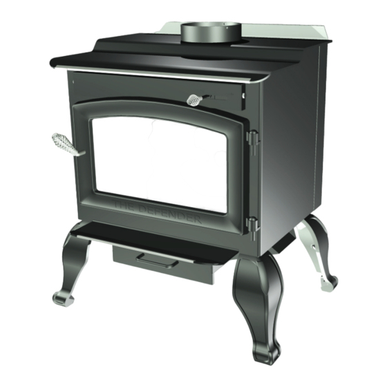
DEFENDER HIGH EFFICIENCY
AIR-TIGHT WOODSTOVE
MODEL TR001B OWNERS MANUAL
U.S. Environmental Protection Agency
Certified to comply with 2015 particulate emissions standards.
Report No. 235-S-01c-2
French version is available for download from the U.S. Stove website: http://www.usstove.com/
La version française est disponible pour téléchargement à partir du site U.S. Stove: http://www.usstove.com
T
TOVE
A
L
RE ER TO MARK
ADD T O AL
O
LT
YOUR
EPA Certifi ed (4.22 gram/hr)
(Save These Instructions)
This unit is not intended to be used as a primary source of heat.
R
A
T
O
L
ROPERTY DAMA
RY,
A
O
TOVE LABEL
ORMAT O
:
TOVE
OT PROPERLY
Y,
TACT LOCAL OR
,
,
LY
:
RUC-
OTE:
,
BE COMPLETED BY A QU
OR
DO NOT
TALLED, A
PAL B
TALLA
Q
Vogelzang
U. S. Stove
227 Industrial Park Road
227 Industrial Park Road
South Pittsburg, Tennessee 37380
South Pittsburg, Tennessee 37380
www.vogelzang.com
www.vogelzang.com
Phone: 800-750-2723
Phone: (800)-750-2723 or (800)-222-6950
o
:
EQ
TALLER!
TALL
A MOB LE HOME
B
OR
Y
r
TALLA
A
MAY
852097C-1902E
Advertisement
Table of Contents

Subscribe to Our Youtube Channel
Related Manuals for Vogelzang International TR001B


Summary of Contents for Vogelzang International TR001B
- Page 1 DEFENDER HIGH EFFICIENCY AIR-TIGHT WOODSTOVE EPA Certifi ed (4.22 gram/hr) MODEL TR001B OWNERS MANUAL (Save These Instructions) U.S. Environmental Protection Agency Certified to comply with 2015 particulate emissions standards. Report No. 235-S-01c-2 French version is available for download from the U.S. Stove website: http://www.usstove.com/ La version française est disponible pour téléchargement à...
-
Page 2: Safety Instructions
Th is manual describes the installation and operation of the Vogelzang, TR001BL wood heater. Th is heater meets the 2015 U.S. Environ- mental Protection Agency's crib wood emission limits for wood heaters sold aft er May 15, 2015. Under specifi c test conditions this heater has been shown to deliver heat at rates ranging from 12,082 to 28,701 Btu/hr. - Page 3 SAFETY INSTRUCTIONS 18. Th e special paints used on your stove may give off some smoke and an odor while they are curing during the fi rst 12 to 15 fi res. Additional smoke and odor may be emitted from the light oils used in construction of the fi re box. Th is should disappear aft er a short period of time and not occur again.
-
Page 4: Tools And Materials Required For Installation
ASSEMBLY INSTRUCTIONS TOOLS AND MATERIALS REQUIRED FOR INSTALLATION TOOLS or equivalent) ing. There are six different sizes brick and two with notches. Note the location of each while removing or refer to fig. 9a, b & c (page 6) for proper location inside firebox. - Page 5 ASSEMBLY INSTRUCTIONS...
-
Page 6: Locating Stove
LOCATING STOVE your local building codes or fire protection C A U T I O N : K E E P F U R N I S H I N G S A N D ordinances. OTHER COMBUSTIBLE MATERIALS AWAY FROM THE STOVE AND OUTSIDE MINIMUM NOTICE: Any wall containing combustible CLEARANCES. -
Page 7: Firebrick Assembly
Fig. 8a – Front View Fig. 8b – Side View Minimum Clearance Minimum Clearance Dimensions Dimensions from Combustible Surfaces from Combustible Surfaces Fig. 8c – Front View Fig. 8d – Side View Minimum Clearance Minimum Clearance Dimensions Dimensions from Combustible Surfaces from Combustible Surfaces FIREBRICK ASSEMBLY Firebrick extends the life of your stove and radiates... -
Page 8: Installation Instructions
LOCATING STOVE A-Size: 9˝x4 ˝x1 ˝ FF-Size: 9˝x4 ˝x1 ˝ M-Size: 9˝x2 ˝x1 ˝ T-Size: 9˝x3 ˝x1 ˝ X-Size: 9˝x4 ˝x1 ˝** Y-Size: 4 ˝x3˝x1 ˝ Z-Size: 3˝x2 ˝x1 ˝ ** X Firebricks are notched for air tube clearance Fig. 9c– Step 3, Back Firebrick Fig. -
Page 9: Chimney Sizing
CHIMNEY SIZING Today’s solid fuel heating appliances are much more efficient than those made in the past. Your heating appliance has been designed to provide the most efficient transfer of heat possible from the least amount of fuel. Controlled combustion is the key to optimum heating performance. -
Page 10: Chimney Connections
CHIMNEY CONNECTIONS IMPORTANT INSTALLATION POINTS Size chimney flue to stove collar. This stove requires a minimum of a 6” diameter flue. Never connect this unit to a chimney serving another appliance. The chimney must meet all minimum height requirements. Never use a chimney to ventilate a cellar or basement. Contact your local building authority for approved methods of installation and any necessary permits and/or inspections. -
Page 11: Fireplace Installation
CHIMNEY CONNECTIONS Do Not use a chimney that is unlined or damaged! If you have any question regarding the condition of the chimney, consult a qualified licensed contractor, qualified engineer, competent mason, certified Chimney Sweep, or a knowledgeable inspector. Consult your insurance company if you cannot find a qualified expert. Many prefabricated fireplaces are of the “zeroclearance fireplace”... - Page 12 CHIMNEY CONNECTIONS 8”/203 mm of liner must remain below the entry NOTE: DO NOT ATTEMPT TO ROUTE THE position. When locating the stove and stovepipe, all CHIMNEY CONNECTOR PIPE THROUGH THE minimum clearances must be observed from com- THROAT OF A FIREPLACE. bustible surfaces including mantels, combustible trim work, ceilings and walls.
- Page 13 CHIMNEY CONNECTOR SYSTEMS & CLEARANCES A. Brick Masonry Minimum 3.5˝/89mm thick brick masonry all framed into combustible wall with a minimum of 12˝/305mm brick separation from clay liner to combustibles. The fireclay liner shall run from outer surface of brick wall to, but not beyond, the inner surface of chimney flue liner and shall be firmly cemented in place.
-
Page 14: Operating Safety Precautions
OPERATING INSTRUCTIONS CAUTION: HOUSE FIRE HAZARDS • DO NOT STORE WOOD ON FLOOR PROTECTOR, UNDERNEATH STOVEPIPE OR ANYWHERE WITHIN MINIMUM CLEARANCES FROM COMBUSTIBLE SURFACES SPECIFIED FOR THIS STOVE. • OVERFIRING MAY CAUSE A HOUSE FIRE. YOU ARE OVERFIRING IF A UNIT OR CHIMNEY CONNECTOR GLOWS RED. -
Page 15: Optimal Fuel Consumption
OPERATING INSTRUCTIONS NOTICE: USE SOLID WOOD MATERIALS ONLY. DO NOT BURN GARBAGE OR FLAMMABLE FLUIDS SUCH AS GASOLINE, NAPHTHA OR ENGINE OIL. DO NOT USE COAL. THIS STOVE IS NOT DESIGNED TO ACCOMMODATE THE AIR FLOW (DRAFT) NECESSARY TO PROPERLY BURN COAL OR COAL PRODUCTS. DO NOT ELEVATE FIRE OR USE GRATES OR ANDIRONS. -
Page 16: Starting A Fire
OPERATING INSTRUCTIONS STARTING A FIRE DO NOT LEAVE STOVE UNATTENDED WITH DOOR OPEN! The top down method of fire building is recommended for this appliance. After making sure that the stove air intake controls are fully open (completely pull-out towards you), Place the largest pieces of wood on the bottom, laid in parallel and close together. Smaller piec- es are placed in a second layer, crossways to the first. -
Page 17: Service Hints
SERVICE HINTS AIR TUBES The air tubes assembled in this unit are designed to provide an accurate mix of secondary air to insure the highest efficiency. Any dam- age or deterioration of these tubes may reduce the efficiency of combustion. The air tubes are held in position by either screws or snap pins. -
Page 18: Chimney Draft
SERVICE HINTS 1. Do not attempt to extend the burn time by using wet wood. Not only does burning wet wood rapidly build up creosote, but it reduces the heat output by up to 25 percent. 2. Burn the stove with the air inlet control wide open for 10-25 minutes every time fresh wood is loaded into the stove. Do not load more than ¼... -
Page 19: Glass Care
SERVICE HINTS 4. Chimney Installation and Maintenance Confirm that all four minimum chimney height requirements listed in the Chimney Connections section of the manual have been met. The physics that link chimney height with draft creation are vital to the proper operation of the stove. Failure to meet each of these minimum requirements will have an adverse affect on draft. - Page 20 SERVICE HINTS WIRING DIAGRAM - MODEL F-6 BLOWER OPTION CAUTION: MOVING PARTS CAN CAUSE DANGER: SHOCK HAZARD. DISCONNECT INJURY. DO NOT OPERATE WITH COVER POWER SOURCE BEFORE INSTALLATION REMOVED. AND WHENEVER SERVICING BLOWER ASSEMBLY. NOTICE: ANY REPLACE- MENT WIRING MUST HAVE E Q U I VA L E N T I N S U L A - TION AND TEMPERATURE RATING (105°C).
- Page 21 When ordering missing or replacement parts, always give the Model Number of the stove, Part Number, and Part Description. Use the illustrations and part lists providedto identify parts. Contact us 1-800-750-2723 at to order parts. Ref. No. Part Description Ref. No. Part Description 1B-01...
- Page 22 When ordering missing or replacement parts, always give the Model Number of the stove, Part Number, and Part When ordering missing or replacement parts, always give the Model Number of the stove, Description. Use the illustrations and part lists providedto identify parts. Part Number, and Part Description.
- Page 23 FLOOR PROTECTOR MATERIAL CALCULATIONS This stove has been tested for and must be installed on a floor protector with the proper Thermal Resistance or R-value as stated in the installation instructions on page 6, “Locating Stove” step 1, of this manual. If the floor protector materials listed in the instructions are not available, materials with an equivalent R-value may be substituted.
- Page 24 This Vogelzang heating appliance is safe when installed properly and will provide you with years of service. However, always exercise good judgement when you are using this stove. You are dealing with FIRE! Fire is inherently dangerous and must be treated with respect. Stay warm and in good health! DO NOT INSTALL THIS STOVE IN A MOBILE HOME, MANUFACTURED HOME, TRAILER OR TENT —...
Need help?
Do you have a question about the TR001B and is the answer not in the manual?
Questions and answers