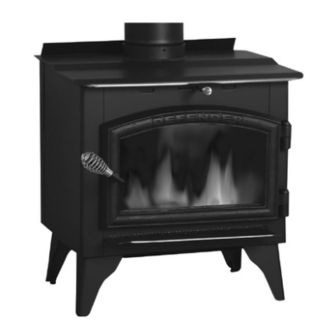
Vogelzang International DEFENDER TR001 Owner's Manual
High efficiency air-tight woodstove
Hide thumbs
Also See for DEFENDER TR001:
- Owner's manual (21 pages) ,
- Owner's manual (20 pages) ,
- Owner's manual (21 pages)
Table of Contents
Advertisement
DEFENDER
AiR-TigHT WOODsTOvE
model TR 001 Owners manual
READ ALL INSTRUCTIONS CAREFULLY
BEFORE STARTING THE INSTALLATION
OR OPERATING THE STOVE. FAILURE TO
FOLLOw INSTRUCTIONS mAY RESULT
IN PROPERTY DAmAGE, BODILY INjURY,
OR EVEN DEATH.
SAFETY INSTRUCTIONS
SAFETY NOTICE: IF THIS STOVE IS NOT PROPERLY INSTALLED A HOUSE/BUILDING FIRE mAY
RESULT. FOR YOUR SAFETY, CONTACT LOCAL BUILDING OR FIRE OFFICIALS ABOUT PERmITS,
RESTRICTIONS, AND INSTALLATION REqUIREmENTS FOR YOUR AREA.
READ ALL INSTRUCTIONS CAREFULLY.
1. The installation of this stove must comply
with your local building code rulings. Please
observe the clearances to combustibles (see
reference figures 1–3). Do not place furni-
ture or other objects within the clearance
area.
2. Verify that the stove is properly installed
before firing the stove for the first time.
After reading these instructions, if you have
any doubt about your ability to complete
your installation properly, you must ob-
tain the services of a professional licensed
installer familiar with all aspects of safe
and correct installation. DO NOT use
temporary or makeshift compromises
during installation.
3. DO NOT store wood, flammable liquids
or other combustible materials too close to
the unit. Refer to certification label on back
of unit and reference figures 1 – 3 in this
manual.
VGZ-026 / 100909.0
HigH EFFiciENcy
™
EPA Certified (4.21grams/hr)
(save this manual for future reference)
DO NOT USE THIS STOVE IN A
mOBILE HOmE, mANUFACTURED HOmE,
TRAILER OR TENT – NO EXCEPTIONS!
This stove meets
Test Standards:
UL 1482-1996 U.S. &
ULC-S627Canada
4. Do not install this stove in a mobile
home, manufactured home, trailer or tent
(NO EXCEPTIONS! per HUD Federal
Standard: 24 CFR Ch.XX).
5. If any parts are missing or defective, please
notify the dealer or manufacturer immediately.
DO NOT OPERATE A STOVE THAT IS
MISSING ANY PARTS!.
6. Do not tamper with combustion air control
beyond normal adjustment capacities.
7. Always connect this stove to a chimney and
vent to the outside. Never vent to another room
or inside a building. DO NOT CONNECT
THIS UNIT TO A CHIMNEY FLUE SERV-
ING ANOTHER APPLIANCE.
8. DO NOT CONNECT a wood burning stove
to an aluminum Type B gas vent. This is not
safe. Use approved masonry or a UL 103 HT
(U.S) / ULC-S629 (Canada) Listed Residen-
tial Type and Building Heating Appliance
Chimney. Use a 6" diameter chimney, that
Vogelzang International Corporation
400 West 17th Street
Holland, Michigan 49423
www.vogelzang.com
Phone: 1-616-396-1911
Fax: 1-616-396-1971
TR001 DEFENDER™ /
continued on next page
Page 1
Advertisement
Table of Contents

Subscribe to Our Youtube Channel
Related Manuals for Vogelzang International DEFENDER TR001


Summary of Contents for Vogelzang International DEFENDER TR001
-
Page 1: Safety Instructions
Type and Building Heating Appliance of unit and reference figures 1 – 3 in this Chimney. Use a 6” diameter chimney, that manual. continued on next page Vogelzang International Corporation 400 West 17th Street Holland, Michigan 49423 www.vogelzang.com Phone: 1-616-396-1911... - Page 2 SAFETY INSTRUCTIONS continued… is high enough to give a good draft. (See is overfired, paint discoloration will occur. specifics in Chimney Connections instruc- 17. This stove has a painted surface which tions). is durable but it will not stand rough handling 9.
-
Page 3: Tools And Materials Required For Installation
ASSEmblY INSTRUCTIONS NOTICE: Vogelzang International Corp. grants no warranty, stated or implied, for the installation or maintenance of your wood stove and assumes no responsibility of any incidental or consequential damages. TOOLS AND mATERIALS REqUIRED FOR INSTALLATION tools Optional Blower Attachment •... - Page 4 lOCATINg STOvE 4. Use 6” round black stove pipe, not dimensions are LARGEST. galvanized stove pipe. Secure pipe sections Failure to follow these minimum clear- with three (3) sheet metal screws in each stove ance requirements may result in an unsafe pipe and/or elbow joint to firmly hold the pipe installation and could cause a fire.
-
Page 5: Firebrick Assembly
lOCATINg STOvE continued… CORNER CLEARANCES 12" 12" Fig. 2 – Top View Minimum Corner Clearances from Combustible Surfaces Fig. 3b – Side View Minimum Clearance Dimensions from Combustible Surfaces FIREBRICk ASSEmBLY Firebrick extends the life of your stove and radiates heat more evenly. Check to see that all firebricks are in their correct positions and have not become misaligned during shipping or assembly. -
Page 6: Connector Pipe Installation
lOCATINg STOvE Fire Brick Dimensions A-Size: 9”x41/2”x11/4” B-Size: 9”x23/4”x11/4” C-Size: 9”x31/4”x11/4” Four (4) A-Size Two (2) A-Size Two (2) B-Size Two (2) C-Size Fig.4b– Step 2, Side Firebrick Installation Fig.4c– Step 3, Back Firebrick Installation CONNECTOR PIPE INSTAllATION 1. The tapered end of the connector stovepipe fits use only corrugated (nonadjustable) elbows. -
Page 7: Chimney Connections
ChImNEY CONNECTIONS mASONRY CHImNEY The stove must be connected to either a ma- sonry or manufactured metal chimney built and Before using an existing masonry chimney, tested to the specifications listed on the previous clean the chimney, inspect the flue liner and make pages. - Page 8 ChImNEY CONNECTIONS continued … mANUFACTURED CHImNEY REFER TO CHIMNEY AND CHIMNEY CONNECTOR MAKER’S INSTRUCTIONS FOR INSTALLATION AND USE. Use only 6” diameter listed chimney UL 103 HT (U.S.) or ULC-S629 (Canada). Chimney made to this listing is High Temperature rated to 2100 degrees Fahrenheit.
-
Page 9: Fireplace Installation
ChImNEY CONNECTIONS continued … is structurally sound, the chimney incorporates a Do not create a hazard in your home by connecting flue liner and make sure it is in good condition. in this manner. FIREPLACE INSTALLATION (A flue liner consists of clay tile that protects the brickwork of a chimney. -
Page 10: Building A Fire
ChImNEY CONNECTIONS continued … expansion of the pipe. Seal this airspace with If you have any questions regarding venting high-temperature caulking or ceramic wool. your stove, contact the manufacturer or contact 6. Secure and seal the damper in the closed posi- the National Fire Protection Association (NFPA) tion using high-temp caulking, ceramic wool, and request a copy of the latest editions of NFPA... -
Page 11: Adding Fuel
OPERATINg INSTRUCTIONS 5. Add large pieces of wood as the fire progresses CAUTION: DO NOT OVERFIRE APPLIANCE. being careful not to overload. (Do not fill fire- YOU ARE OVERFIRING IF THE CHImNEY box beyond firebrick area.) An ideal coal bed of CONNECTORS OR STOVE GLOwS RED. -
Page 12: Service Hints
SERvICE hINTS CHImNEY DRAFT or breaks during operation. Draft is a function of the chimney, not the 5. Never attempt to clean the glass while the unit stove — do not expect the stove to draw. Smoke is hot. If deposits are not very heavy, normal spillage into the house or excess buildup of conden- glass cleaners are adequate using a soft, non- abrasive cleaning pad. -
Page 13: Chimney Maintenance
SERvICE hINTS continued … Door gasket replacement Procedure: CAUTION: A CHImNEY FIRE mAY CAUSE IGNI- 1. Ensure appliance is not in operation and is TION OF wALL STUDS OR RAFTERS wHICH thoroughly cooled. wERE ASSUmED TO BE A SAFE DISTANCE FROm THE CHImNEY. - Page 14 PARTS - TR001 DEFENDER hIgh-EFFICIENCY STOvE When ordering missing or replacement parts, always give the model Number of the stove, Part Number, and Part Description. Use the illustrations and part lists provided to identify parts. 6 (9) 7 (9) 8 (9) 11, 12, 13 1, 24 Part No.
- Page 15 PARTS - TR001 DEFENDER hIgh-EFFICIENCY STOvE When ordering missing or replacement parts, always give the model Number of the stove, Part Number, and Part Description. Use the illustrations and part lists provided to identify parts. Part No. Description qty. Door assembly (complete) ......1 Handle Assembly (complete) ....
- Page 16 FlOOR PROTECTOR mATERIAl CAlCUlATIONS This stove has been tested for and must be installed on a floor protector with the proper Thermal Resistance or R-value as stated in the installation instructions on page 3, “Locating Stove” step 1, of this manual. If the floor protector materials listed in the instructions are not available, materials with an equivalent R-value may be substituted.
- Page 17 ChImNEY CONNECTOR SYSTEmS & ClEARANCES A. Brick masonry Minimum 3.5-inch thick brick masonry all framed into combustible wall with a minimum of 2-inch brick separation from clay liner to combustibles. The fireclay liner shall run from outer surface of brick wall to, but not beyond, the inner surface of chimney flue liner and shall be firmly cemented in place.
- Page 18 “FOR GOD SO LOVED THE wORLD THAT HE GAVE HIS ONLY BEGOTTEN SON, THAT wHOEVER BELIEvES IN HIM SHaLL NoT PERISH BUT HavE ETERNaL LIFE” jOHN 3:16 mADE IN CHINA Vogelzang International Corporation 400 West 17th Street Holland, Michigan 49423 www.vogelzang.com...
Need help?
Do you have a question about the DEFENDER TR001 and is the answer not in the manual?
Questions and answers