Vogelzang International TR009 Owner's Manual
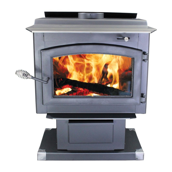
The performer high-efficiency woodstove
Hide thumbs
Also See for TR009:
- Owner's manual (24 pages) ,
- Owner's manual (22 pages) ,
- Owner's manual (24 pages)
Table of Contents
Advertisement
Quick Links
THE PERFORMER
HIGH-EFFICIENCY WOODSTOVE
EPA Certified (3.89 grams/hr.)
Model TR009 Owners Manual
(Save These Instructions)
Le manuel de langue français est disponible á www.usstove.com
French language manual is available at www.usstove.com
U.S. Environmental Protection Agency
Certified to comply with 2015 particulate emissions standards.
U.S. Stove Company
227 Industrial Park Road,
P.O. Box 151
South Pittsburg, TN 37380
Phone 1-800-750-2723
www.Vogelzang.com
852171B-1903E
Advertisement
Table of Contents

Subscribe to Our Youtube Channel
Related Manuals for Vogelzang International TR009


Summary of Contents for Vogelzang International TR009
- Page 1 THE PERFORMER HIGH-EFFICIENCY WOODSTOVE EPA Certified (3.89 grams/hr.) Model TR009 Owners Manual (Save These Instructions) Le manuel de langue français est disponible á www.usstove.com French language manual is available at www.usstove.com U.S. Environmental Protection Agency Certified to comply with 2015 particulate emissions standards.
- Page 2 This manual describes the installation and operation of the Vogelzang, TR009 wood heater. This heater meets the 2015 U.S. Environmental Protection Agency's crib wood emission limits for wood heaters sold after May 15, 2015. Under spe- cific test conditions this heater has been shown to deliver heat at rates ranging from 10,889 to 29,421 Btu/hr.
-
Page 3: Safety Instructions
SAFETY INSTRUCTIONS 18. This stove has a painted surface which is durable but it will not stand rough handling or abuse. When installing your stove, use care in handling. 19. Clean exterior with soap and warm water when stove is not hot. Do not use any acids or scouring soap, as these solvents wear and dull the finish. -
Page 4: Tools And Materials Required For Installation
ASSEMBLY INSTRUCTIONS NOTICE: Vogelzang International Corp. grants no warranty, stated or implied, for the installation or maintenance of your wood stove and assumes no responsibility of any incidental or consequential damages. the side walls of the stove to direct combustion gasses... - Page 5 ASSEMBLY INSTRUCTIONS 8. Align four (4) corner mounting studs with holes in pedestal top (Figure 7). Secure with four (4) hex nuts (E). 9. Tip the stove assembly upright. 10. Set the ash drawer inside the open box formed by the pedestal front and sides. Figure 5 –...
-
Page 6: Locating Stove
LOCATING STOVE 1. The stove must be placed on solid concrete, solid masonry, or when installed on a combustible floor, on an Under- writers Laboratories Listed Type 2 floor protector listed to UL standard UL 1618, such as Hy-C or Imperial Model UL3648BK (US) or UL4049BK (CAN). - Page 7 LOCATING STOVE CAUTION: KEEP FURNISHINGS AND OTHER COMBUSTIBLE MATERIALS AWAY FROM THE STOVE. NOTE: BEFORE FIRING WOODSTOVE SLIDE FIREBRICKS TOWARDS THE REAR SO NO GAPS REMAIN BETWEEN BRICKS. Figure 11a – Front View Figure 11b – Side View Minimum Clearance Dimensions from Combustible Surfaces Figure 11c –...
-
Page 8: Firebrick Assembly
LOCATING STOVE Figure 12 – Top View Minimum Corner Clearances from Combustible Surfaces 12˝/30.5cm (US & CDN) FIREBRICK ASSEMBLY Firebrick extends the life of your stove and radiates heat more evenly. Check to see that all firebricks are in their correct positions and have not become misaligned during shipping or assembly. -
Page 9: Connector Pipe Installation
CONNECTOR PIPE INSTALLATION NOTE: CONNECTOR PIPE IS NOT INCLUDED. TO PURCHASE, VISIT YOUR LOCAL HARDWARE, HOME, OR BUILDING CENTER. SEE “LOCATING STOVE” PAGE 7 FOR ADDITIONAL SPECIFICATIONS. Connector pipe is used to make the connection from the final positioning of your stove to an approved chimney. Connec- tor pipe is NOT included as part of the stove. -
Page 10: Chimney Connections
CHIMNEY CONNECTIONS The stove must be connected to either a lined masonry or CHIMNEY THIMBLE manufactured metal chimney built and tested to the speci- FLUE COLLAR fications listed on the previous pages. Chimneys perform 6˝ ROUND two functions: 24 ga . BLACK 5/8"... -
Page 11: Importance Of Proper Draft
CHIMNEY CONNECTIONS MANUFACTURED CHIMNEY REFER TO CHIMNEY AND CHIMNEY CONNECTOR MAKER’S INSTRUCTIONS FOR INSTALLATION AND USE. Use only 6˝/152mm diameter chimney with UL 103 HT (USA) or ULC-S629 (CDN) listing. Chimney made to this listing is High Temperature rated to 2100°F/1149°C. Use chimney from only one manufacturer. -
Page 12: Fireplace Installation
CHIMNEY CONNECTIONS CAUTION: NOT ALL FIREPLACE CHIMNEYS ARE SUITABLE FOR CONVERSION TO ACCOMMODATE A WOOD STOVE. CHECK WITH A QUALIFIED EXPERT. Many prefabricated fireplaces are of the “zero-clearance remain below the entry position. When locating the fireplace” category. These consist of multi layered metal stove and stovepipe, all minimum clearances must be construction. - Page 13 CHIMNEY CONNECTOR SYSTEMS & CLEARANCES NOTE: IN CANADA, THE INSTALLATION MUST CONFORM TO CAN/CSA-B365 WHEN PASSING THROUGH COM- BUSTIBLE CONSTRUCTION. A. Brick Masonry Minimum 3.5˝/89mm thick brick masonry all framed into combustible wall with a minimum of 12˝/305mm brick separation from clay liner to combustibles. The fireclay liner shall run from outer surface of brick wall to, but not beyond, the inner surface of chimney flue liner and shall be firmly cemented in place.
-
Page 14: Operating Safety Precautions
OPERATING INSTRUCTIONS CAUTION: HOUSE FIRE HAZARDS • DO NOT STORE WOOD ON FLOOR PROTECTOR, UNDERNEATH STOVEPIPE, OR ANYWHERE WITHIN MINIMUM CLEARANCES FROM COMBUSTIBLE SURFACES SPECIFIED FOR THIS STOVE. • OVER FIRING MAY CAUSE A HOUSE FIRE. YOU ARE OVER FIRING IF A UNIT OR CHIMNEY CONNECTOR GLOWS RED. -
Page 15: Optimal Fuel Consumption
OPERATING INSTRUCTIONS NOTICE: USE SOLID WOOD MATERIALS ONLY. DO NOT BURN GARBAGE OR FLAMMABLE FLUIDS SUCH AS GASOLINE, NAPHTHA OR ENGINE OIL. DO NOT USE COAL. THIS STOVE IS NOT DESIGNED TO ACCOMMODATE THE AIR FLOW (DRAFT) NECESSARY TO PROPERLY BURN COAL OR COAL PRODUCTS. DO NOT ELEVATE FIRE OR USE GRATES OR ANDIRONS. -
Page 16: Starting A Fire
OPERATING INSTRUCTIONS STARTING A FIRE DO NOT LEAVE STOVE UNATTENDED WITH DOOR OPEN! The top down method of fire building is recommended for this appliance. After making sure that the stove air intake con- trols are fully open (completely pull-out towards you), Place the largest pieces of wood on the bottom, laid in parallel and close together. -
Page 17: Air Tubes
OPERATING INSTRUCTIONS / SERVICE HINTS • Burn small, intense fires instead of large, slow burning fires when possible • Learn your appliance’s operating characteristics to obtain optimum performance • Burning unseasoned wet wood only hurts your stoves efficiency and leads to accelerated creosote buildup in your chimney AIR TUBES The air tubes assembled in this unit are designed to provide an accurate mix of secondary air to insure the highest ef-... -
Page 18: Service Hints
SERVICE HINTS fire. As a result, creosote residue accumulates on the flue lining. When ignited this creosote makes an extremely hot fire. The chimney connector and chimney should be inspected at least once every two months during the heating season to determine if a creosote buildup has occurred. -
Page 19: Glass Care
SERVICE HINTS stove. Masonry chimneys will take longer to warm than manufactured chimneys on account of their greater structural mass. Chimneys that have a flue diameter larger than the stove outlet take more heat to warm, thus resulting in a faster cooling of the hot gases needed to build or maintain draft. - Page 20 SERVICE HINTS WIRING DIAGRAM - MODEL F-6 BLOWER OPTION CAUTION: MOVING PARTS CAN CAUSE DANGER: SHOCK HAZARD. DISCONNECT INJURY. DO NOT OPERATE WITH COVER POWER SOURCE BEFORE INSTALLATION REMOVED. AND WHENEVER SERVICING BLOWER ASSEMBLY. NOTICE: ANY REPLACE- MENT WIRING MUST HAVE E Q U I VA L E N T I N S U L A - TION AND TEMPERATURE RATING (105°C).
-
Page 21: Repair Parts
REPAIR PARTS... -
Page 22: Parts List
PARTS LIST Ref. No. Part No. Description Qty. 09-01 C-Cast Fiberboard HP-09 Nuts (Pedestal/Stove Attachment) 09-02 Handle, Slide Draft Spring 09-03 Nickle Trim, Top Plate 09-04 Nickle Trim, Hearth 86777 Tube, Air Secondary (Rear) 86778 Tube, Air Secondary (Mid-Rear) 86779 Tube, Air Secondary (Mid-Front) 86780 Tube, Air Secondary (Front) - Page 23 REPAIR PARTS Fire Brick Sides Fire Brick Back Fire Brick Bottom...
- Page 24 NOTES...
- Page 25 NOTES...
- Page 26 NOTES...
- Page 27 FLOOR PROTECTOR MATERIAL CALCULATIONS This stove has been tested for and must be installed on a floor protector with the proper Thermal Resistance or R-value as stated in the installation instructions under “Locating Stove” section, step 1, of this manual. If the floor protector materials listed in the instructions are not available, materials with an equivalent R-value may be substituted.
- Page 28 U. S. Stove Company 227 Industrial Park Road South Pittsburg, Tennessee 37380 www.usstove.com Phone: 800-750-2723...
Need help?
Do you have a question about the TR009 and is the answer not in the manual?
Questions and answers