Table of Contents
Advertisement
Quick Links
Advertisement
Table of Contents

Summary of Contents for MiLAN MIL-S24000T
- Page 1 MIL-S24000T 24-Port 1000BASE-T Gigabit Ethernet Switch USER GUIDE...
- Page 2 In no event shall MiLAN Technology be liable for incidental or consequential damages, costs, or expenses arising out of or in connection with the performance of the product delivered hereunder.
-
Page 3: Table Of Contents
Table of Contents 1. Introduction Gigabit Ethernet Technology Switching Technology Features Package Contents 2. Hardware Description Front Panel Rear Panel LED Indicators 3. Hardware Installation Desktop Installation Rack mounted Installation Power On 4. Technical Specifications General Specifications Physical and Environmental Specifications Performance Specifications Appendix A: Regulatory Information... -
Page 4: Introduction
Switching Technology Another key development pushing the limits of Ethernet technology is in the field of switching technology. A switch bridges Ethernet packets at the MAC address level of the Ethernet protocol transmitting among connected Ethernet or fast Ethernet LAN segments. -
Page 5: Features
Features The MIL-S24000T Gigabit Ethernet Switch was designed for easy installation and high performance in an environment where traffic on the network and the number of users increase continuously. -
Page 6: Package Contents
Package Contents Unpack the contents of the package and verify them against the checklist below. MIL-S24000T Gigabit Ethernet Switch AC Power Cord Rack Mount Ears Four Adhesive Rubber Feet User's Guide Warranty Card If any item is missing or damaged, please contact your local dealer for service. -
Page 7: Hardware Description
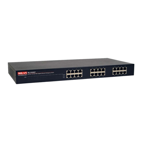
Ethernet ports and the LED Indicators for the unit, which displays the conditions of the Gigabit Ethernet Switch and the status of the network. Figure 2-1. Front Panel view of the MIL-S24000T Gigabit Ethernet Switch Rear Panel The rear panel of the Gigabit Ethernet Switch consists of an AC power connecter and a power switch. -
Page 8: Led Indicators
There are three LED-indicators for each Gigabit Ethernet port and one Power LED for the Unit. Figure 2-3. LED Indicators on the MIL-S24000T Gigabit Ethernet Switch POWER The Power LED indicator is solid green when the Gigabit Ethernet Switch is receiving power. -
Page 9: Hardware Installation
Hardware Installation Desktop Installation Set the switch on a sufficiently large flat space with a power outlet nearby. The surface where you put your switch should be clean, smooth, level, and sturdy. Provide enough clearance around the switch to allow attachment of cables, power cord and air circulation. -
Page 10: Rack Mounted Installation
Rack-mounted Installation The MIL-S24000T comes with a rack-mounted kit and can be mounted in an EIA standard size, 19-inch rack. The Switch can be placed in a wiring closet with other equipment. Perform the following steps to rack mount the switch: A. -
Page 11: Power On
Power On Connect the power cord to the power socket on the rear panel of the Switch. Connect the other end of the cord to an appropriate power outlet. Press the power On/Off switch to the on position and check the power indicator on the front panel... -
Page 12: Technical Specifications
Technical Specifications General Specifications Standards: IEEE 802.3ab 1000BASE-T IEEE 802.3u 100BASE-TX IEEE 802.3 10BASE-T IEEE 802.3x Flow Control Protocol: CSMA/CD Data Transfer Ethernet: Rate: Fast Ethernet: G igabit Ethernet: 2000Mbps (Full-duplex) Topology: Star Network Cables: Ethernet: Fast Ethernet: Gigabit Ethernet: 4-pair UTP Cat. 5, Number of Ports: Twenty-four (24) 1000BASE-T Gigabit Ethernet ports Physical and Environmental Specifications... -
Page 13: Performance Specifications
Performance Specifications Transmission Store-and-forward Method: RAM Buffer: 400K Bytes per device Filtering Address 8K MAC address per device Table: MAC Address Self-learning, auto-aging Learning:... -
Page 14: Ce Mark Warning
Appendix A: Regulatory Information FCC Warning This equipment has been tested and found to comply with the regulations for a Class A digital device, pursuant to Part 15 of the FCC Rules. These limits are designed to provide reasonable protection against harmful interference when the equipment is operated in a commercial environment. - Page 15 condition is not achieved due to uneven mechanical loading. d) Circuit Overloading- Consideration should be given to the connection of the equipment to the supply circuit and the effect that overloading of circuits might have on over current protection and supply wiring.
- Page 16 90000423 Rev A...


Need help?
Do you have a question about the MIL-S24000T and is the answer not in the manual?
Questions and answers