ATEN CE250A User Manual
Hide thumbs
Also See for CE250A:
- User manual (31 pages) ,
- User manual (31 pages) ,
- Quick start manual (2 pages)
Table of Contents
Advertisement
Quick Links
Advertisement
Table of Contents

Subscribe to Our Youtube Channel
Related Manuals for ATEN CE250A


Summary of Contents for ATEN CE250A
- Page 1 KVM Extender CE250A User Manual www.aten.com...
-
Page 2: Emc Information
CE250 User Manual EMC Information FEDERAL COMMUNICATIONS COMMISSION INTERFERENCE STATEMENT: This equipment has been tested and found to comply with the limits for a Class A digital device, pursuant to Part 15 of the FCC Rules. These limits are designed to provide reasonable protection against harmful interference when the equipment is operated in a commercial environment. -
Page 3: Sj/T 11364-2006
CE250 User Manual SJ/T 11364-2006 The following contains information that relates to China. -
Page 4: User Information
86-10-5255-0110 Japan 81-3-5615-5811 Korea 82-2-467-6789 North America 1-888-999-ATEN ext 4988 United Kingdom 44-8-4481-58923 User Notice All information, documentation, and specifications contained in this manual are subject to change without prior notification by the manufacturer. The manufacturer makes no representations or warranties, either expressed or implied, with respect to the contents hereof and specifically disclaims any warranties as to merchantability or fitness for any particular purpose. -
Page 5: Package Contents
© Copyright 2007–2015 ATEN® International Co., Ltd. Manual Part No. PAPE-0222-AT3G Manual Date: 2015-4-30 ATEN and the ATEN logo are registered trademarks of ATEN International Co., Ltd. All rights reserved. All other brand names and trademarks are the registered property of their respective owners. -
Page 6: Table Of Contents
CE250 User Manual Contents EMC Information..........ii RoHS . - Page 7 CE250 User Manual Appendix Safety Instructions......... . . 17 General .
-
Page 8: About This Manual
CE250 User Manual About this Manual This User Manual is provided to help you get the most from your system. It covers all aspects of installation, configuration and operation. An overview of the information found in the manual is provided below. Chapter 1, Introduction, introduces you to the CE250 system. -
Page 9: Conventions
For information about all ATEN products and how they can help you connect without limits, visit ATEN on the Web or contact an ATEN Authorized Reseller. Visit ATEN on the Web for a list of locations and telephone numbers: International http://www.aten.com... - Page 10 CE250 User Manual This Page Intentionally Left Blank...
-
Page 11: Chapter 1 Introduction
Chapter 1 Introduction Overview The CE250 KVM Extender allows access to a computer system from a remote console (keyboard, monitor, and mouse). It is perfect for factory and construction sites, or any type of installation where the console needs to be in a conveniently accessible location, but you want the system equipment to reside in a safe place –... -
Page 12: Features
CE250 **The EDID data for a widescreen is sent from the local video output port. For widescreen modes and displays connect the monitor to the local video output port or use an ATEN EDID emulator. -
Page 13: Requirements
Chapter 1. Introduction Requirements Console A VGA, SVGA, or Multisync monitor capable of the highest resolution that you will be using on any computer in the installation A PS/2 keyboard A PS/2 mouse Note: 1. If you connect a DDC type monitor to the Local Unit, the monitor that connects to the Remote Unit must be able to support the highest video resolution that the DDC monitor can provide. -
Page 14: Operating Systems
CE250 User Manual Operating Systems Supported operating systems are shown in the table, below: Version Windows 2000 and higher Linux RedHat 7.1 and higher SuSE 9.0 and higher Mandriva (Mandrake) 9.0 and higher UNIX 4.3, 5L (5.2, 5.3) FreeBSD 4.2, 4.5 Novell Netware 6.0 and higher... -
Page 15: Components
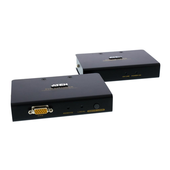
Chapter 1. Introduction Components CE250 (Local Unit) Front View Description Function Grounding The grounding wire (used to ground the unit) attaches here. Terminal KVM Port The KVM cable that links the CE250 to your computer plugs in here. Only KVM cables designed to work with this switch can be used.* Remote LED The Local Unit has two LEDs to indicate the operating status... -
Page 16: Ce250Ar (Remote Unit) Front View
CE250 User Manual CE250 (Remote Unit) Front View Description Function Grounding The grounding wire (used to ground the unit) attaches here. Terminal On Line LED These LEDs indicate the operating status of the Local and Remote units. See CE250AR (Remote Unit), page 16, for Power LED details. -
Page 17: Ce250Al / Ce250Ar Rear View
Chapter 1. Introduction CE250 / CE250 Rear View Description Function Power Jack The cable from the DC Power Adapter plugs into this jack.* Mouse Port The console mice plug into these ports. Keyboard Port The console keyboards plugs into these ports. Link Port The Cat 5 cable that connects the Remote and Local units plugs into this connector. - Page 18 CE250 User Manual This Page Intentionally Left Blank...
-
Page 19: Chapter 2. Hardware Setup
Chapter 2 Hardware Setup 1. Important safety information regarding the placement of this device is provided on page 17. Please review it before proceeding. 2. Make sure that power to all the devices you will be installing has been turned off. You must unplug the power cords of any computers that have the Keyboard Power On function. - Page 20 CE250 User Manual 2. Use the screws you just removed to attach the mounting bracket that came with your package to the unit: 3. Screw the bracket into any convenient location on the rack.
-
Page 21: Installation
Chapter 2. Hardware Setup Installation Grounding To prevent damage to your installation it is important that all devices are properly grounded. 1. Use a grounding wire to ground both units by connecting one end of the wire to the grounding terminal, and the other end of the wire to a suitable grounded object. - Page 22 CE250 User Manual (Continued from previous page.) 4. For increased grounding protection, use STP (shielded twisted pair) cable to connect the local and remote units. There are two methods that can be used: a) In addition to the eight paired wires, STP cable also contains a grounding wire.
-
Page 23: Connecting Up
Chapter 2. Hardware Setup Connecting Up Refer to the installation diagram on the following page (the numbers in the diagram correspond to the numbers of the steps), as you perform these steps: 1. Plug the cables from the local console devices (keyboard, monitor, mouse), into their ports on the rear panel of the Local Unit (CE250 2. - Page 24 CE250 User Manual CE-250AL CE-250AL CE-250AR...
-
Page 25: Chapter 3 Operation
Chapter 3 Operation Operating Modes The CE250 KVM Extender has two operating modes: Local and Remote, as described in the table below: Mode Description Local Only the local console has KVM (keyboard, video, mouse) access. The remote console’s monitor is blank, and the remote console’s keyboard and mouse input is disabled. -
Page 26: Led Display
CE250 User Manual LED Display The CE250 Local and Remote Units have front panel LEDs to indicate their operating status, as shown in the tables, below: CE250 (Local Unit) Operating Mode Local Auto Local Lights to indicate Lights when the local console is active (the Remote that the local LED is out). -
Page 27: Appendix
Appendix Safety Instructions General Read all of these instructions. Save them for future reference. Follow all warnings and instructions marked on the device. This device is for indoor use only. Do not place the device on any unstable surface (cart, stand, table, etc.). If the device falls, serious damage will result. - Page 28 CE250 User Manual extension cord ampere rating. Make sure that the total of all products plugged into the wall outlet does not exceed 15 amperes. To help protect your system from sudden, transient increases and decreases in electrical power, use a surge suppressor, line conditioner, or un-interruptible power supply (UPS).
-
Page 29: Technical Support
Appendix Technical Support International For online technical support – including troubleshooting, documentation, and software updates: http://support.aten.com For telephone support, see Telephone Support, page iii. North America Email Support support@aten-usa.com Online Troubleshooting http://www.aten-usa.com/support Technical Documentation Support Software Updates Telephone Support 1-888-999-ATEN ext 4988 When you contact us, please have the following information ready beforehand: Product model number, serial number, and date of purchase. -
Page 30: Specifications
CE250 User Manual Specifications Function CE250 CE250 Console Selection 1 x Pushbutton Connectors Console Ports 1 x 6-pin Mini-DIN F (Purple) Video 1 x HDB-15 F Mouse 1 x 6-pin Mini-DIN F (Green) KVM Ports 1 x SPHD-15 F Power 1 x DC Jack Unit to Unit 1 x RJ-45... -
Page 31: Tp Wiring Diagram And Pin Assignments
Appendix TP Wiring Diagram and Pin Assignments PAIR 3 Assignment /V OUT B PAIR 2 PAIR 1 PAIR 4 V OUT B /V OUT G 1 2 3 4 5 6 /V OUT R W-O O W-G Bl W-Bl G W-Br Br V OUT R JACK POSITIONS V OUT G... -
Page 32: Limited Warranty
CE250 User Manual Limited Warranty IN NO EVENT SHALL THE DIRECT VENDOR'S LIABILITY EXCEED THE PRICE PAID FOR THE PRODUCT FROM THE DIRECT, INDIRECT, SPECIAL, INCIDENTAL OR CONSEQUENTIAL DAMAGES RESULTING FROM THE USE OF THE PRODUCT, DISK OR ITS DOCUMENTATION. The direct vendor makes no warranty or representation, expressed, implied, or statutory with respect to the contents or use of this documentation, and specially disclaims its quality, performance, merchantability, or fitness for any particular purpose. - Page 33 Index Registration, iv Operating Modes, 15 CE250AL Front View, 5 Rear View, 7 Rack mounting, 9 CE250AR Rear View, 7 Front View, 6 Requirements Rear View, 7 Cables, 3 Components, 5 Operating Systems, 4 CE250AL Front View, 5 OS Support, 4 CE250AR Front View, 6 RoHS, ii Rear View, 7...
Need help?
Do you have a question about the CE250A and is the answer not in the manual?
Questions and answers