ATEN CE250a User Manual
Hide thumbs
Also See for CE250a:
- User manual (31 pages) ,
- Quick start manual (2 pages) ,
- User manual (33 pages)
Table of Contents
Advertisement
Quick Links
Download this manual
See also:
User Manual
Advertisement
Table of Contents

Subscribe to Our Youtube Channel
Related Manuals for ATEN CE250a


Summary of Contents for ATEN CE250a
- Page 1 KVM Extender CE250 User Manual www.aten.com...
-
Page 2: Fcc Information
CE250 User Manual FCC Information This is an FCC Class A product. In a domestic environment this product may cause radio interference in which case the user may be required to take adequate measures. This equipment has been tested and found to comply with the limits for a Class A digital device, pursuant to Part 15 of the FCC Rules. -
Page 3: User Information
Online Registration Be sure to register your product at our online support center: International – http://support.aten.com North America – http://www.aten-usa.com/product_registration Online Support Online technical support is available to ATEN customers through our support center. See Technical Support, page xi, for details. -
Page 4: Safety Instructions
CE250 User Manual Safety Instructions General Read all of these instructions. Save them for future reference. Follow all warnings and instructions marked on the device. Do not place the device on any unstable surface (cart, stand, table, etc.). If the device falls, serious damage will result. Do not use the device near water. - Page 5 CE250 User Manual Position system cables and power cables carefully; Be sure that nothing rests on any cables. When connecting or disconnecting power to hot-pluggable power supplies, observe the following guidelines: Install the power supply before connecting the power cable to the power supply.
-
Page 6: Rack Mounting
CE250 User Manual Rack Mounting Before working on the rack, make sure that the stabilizers are secured to the rack, extended to the floor, and that the full weight of the rack rests on the floor. Install front and side stabilizers on a single rack or front stabilizers for joined multiple racks before working on the rack. -
Page 7: Package Contents
© Copyright 2006 ATEN® International Co., Ltd. Manual Part No. PAPE-0222-1ATG Printing Date: 04/2007 ATEN and the ATEN logo are registered trademarks of ATEN International Co., Ltd. All rights reserved. All other brand names and trademarks are the registered property of their respective owners. -
Page 8: Table Of Contents
CE250 User Manual Contents FCC Information ..........ii SJ/T 11364-2006 . - Page 9 CE250 User Manual Appendix Specifications ..........17 TP Wiring Diagram and Pin Assignments .
-
Page 10: About This Manual
CE250 User Manual About this Manual This User Manual is provided to help you get the most from your c/c system. It covers all aspects of installation, configuration and operation. An overview of the information found in the manual is provided below. Chapter 1, Introduction, introduces you to the CE250 system. -
Page 11: Technical Support
2. Call the ATEN Technical Support Center: 886-2-8692-6959 Email Support Email your questions and concerns to: support@aten.com Online Support 1. Online technical support is available to ATEN custom- ers through our e-Support Center: Technical Support http://support.aten.com Troubleshooting 2. Online troubleshooting that describes the most... -
Page 12: Product Information
For information about all ATEN products and how they can help you connect without limits, visit ATEN on the Web or contact an ATEN Authorized Reseller. Visit ATEN on the Web for a list of locations and telephone numbers International – http://www.aten.com... -
Page 13: Introduction
Chapter 1 Introduction Overview The CE250 KVM Extender allows access to a computer system from a remote console (keyboard, monitor, and mouse). It is perfect for factory and construction sites, or any type of installation where the console needs to be in a conveniently accessible location, but you want the system equipment to reside in a safe place - away from dust, dirt, and harsh environmental influences. -
Page 14: Features
CE250 User Manual Features Cat 5 (or higher) cable to connect the Local and Remote Units – up to 150 m apart Dual console operation - control your system from both the local and remote PS/2 keyboard, mouse and monitor consoles Pushbutton selection of the active console High resolution video –... -
Page 15: Requirements
1. Introduction Requirements Console A VGA, SVGA, or Multisync monitor capable of the highest resolution that you will be using on any computer in the installation A PS/2 style keyboard A PS/2 style mouse Note: 1. If you connect a DDC type monitor to the Local Unit, the monitor that connects to the Remote Unit must be able to support the highest video resolution that the DDC monitor can provide. -
Page 16: Operating Systems
CE250 User Manual Operating Systems Supported operating systems are shown in the table, below: Version Windows 2000 and higher Linux RedHat 7.1 and higher SuSE 9.0 and higher Mandriva (Mandrake) 9.0 and higher UNIX 4.3, 5L (5.2, 5.3) FreeBSD 4.2, 4.5 Novell Netware 6.0 and higher... -
Page 17: Components
1. Introduction Components CE250 (Local Unit) Front View Description Function Grounding The grounding wire (used to ground the unit) attaches here. Terminal KVM Port The KVM cable that links the CE250 to your computer plugs in here. Only KVM cables designed to work with this switch can be used.* Remote LED The Local Unit has two LEDs to indicate the operating status... -
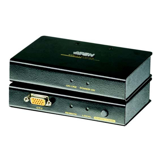
Page 18: (Remote Unit) Front View
CE250 User Manual CE250 (Remote Unit) Front View Description Function Grounding The grounding wire (used to ground the unit) attaches here. Terminal On Line LED These LEDs indicate the operating status of the Local and Remote units. See CE250 (Remote Unit),page 16, for Power LED details. - Page 19 1. Introduction CE250 / CE250 Rear View Description Function Power Jack The cable from the DC Power Adapter plugs into this jack.* Mouse Port The console mice plug into these ports. Keyboard Port The console keyboards plugs into these ports. Link Port The Cat 5 cable that connects the Remote and Local units plugs into this connector.
- Page 20 CE250 User Manual This Page Intentionally Left Blank...
-
Page 21: Rack Mounting
Chapter 2 Hardware Setup 1. Important safety information regarding the placement of this device is provided on page iv. Please review it before proceeding. 2. Make sure that power to all the devices you will be connecting up have been turned off. You must unplug the power cords of any computers that have the Keyboard Power On function. - Page 22 CE250 User Manual 2. Use the screws you just removed to attach the mounting bracket that came with your package to the unit: 3. Screw the bracket into any convenient location on the rack.
-
Page 23: Installation
2. Hardware Setup Installation Grounding To prevent damage to your installation it is important that all devices are properly grounded. 1. Use the two grounding wires supplied with this package to ground both units by connecting one end of the wire to the grounding terminal, and the other end of the wire to a suitable grounded object. - Page 24 CE250 User Manual (Continued from previous page.) 4. For increased grounding protection, use STP (shielded twisted pair) cable to connect the local and remote units. There are two methods that can be used: a) In addition to the eight paired wires, STP cable also contains a grounding wire.
-
Page 25: Connecting Up
2. Hardware Setup Connecting Up Refer to the installation diagram on the following page (the numbers in the diagram correspond to the numbers of the steps), as you perform these steps: 1. Plug the cables from the local console devices (keyboard, monitor, mouse), into their ports on the rear panel of the Local Unit (CE250 2. - Page 26 CE250 User Manual CE-250AL CE-250AL CE-250AR...
-
Page 27: Operating Modes
Chapter 3 Operation Operating Modes The CE250 KVM Extender has two operating modes: Local and Remote, as described in the table below: Mode Description Local Only the local console has KVM (keyboard, video, mouse) access. The remote console’s monitor is blank, and the remote console’s keyboard and mouse input is disabled. -
Page 28: Led Display
CE250 User Manual LED Display The CE250 Local and Remote Units have front panel LEDs to indicate their operating status, as shown in the tables, below: CE250 (Local Unit) Operating Mode Local Auto Local Lights to indicate 1. Lights when the local console is active (the that the local Remote LED is out). -
Page 29: Appendix
Appendix Specifications Function CE250 CE250 Console Selection 1 x Pushbutton Connectors Console Ports 1 x 6-pin Mini-DIN F (Purple) Video 1 x HDB-15 F Mouse 1 x 6-pin Mini-DIN F (Green) KVM Ports 1 x SPHD-15 F Power 1 x DC Jack Unit to Unit 1 x RJ-45 LEDs... -
Page 30: Tp Wiring Diagram And Pin Assignments
CE250 User Manual TP Wiring Diagram and Pin Assignments PAIR 3 Assignment /V OUT B PAIR 2 PAIR 1 PAIR 4 V OUT B /V OUT G 1 2 3 4 5 6 /V OUT R W-O O W-G Bl W-Bl G W-Br Br V OUT R JACK POSITIONS V OUT G... -
Page 31: Index
Index Registration, iii Support, iii CE250AL Operating Modes, 15 Front View, 5 Overview, 1 Rear View, 7 CE250AR Front View, 6 Rack Mounting Rear View, 7 Safety information, vi Components Rack mounting, 9 CE250AL Front View, 5 Rear View, 7 CE250AR Front View, 6 Requirements Rear View, 7...
Need help?
Do you have a question about the CE250a and is the answer not in the manual?
Questions and answers