Table of Contents
Advertisement
Quick Links
Advertisement
Table of Contents

Subscribe to Our Youtube Channel
Related Manuals for ATEN CE610L


Summary of Contents for ATEN CE610L
- Page 1 USB 2.0 DVI KVM Extender CE610 User Manual www.aten.com...
-
Page 2: Fcc Information
CE610 User Manual FCC Information Warning: This is a class A product. In a domestic environment this product may cause radio interference in which case the user may be required to take adequate measures. FEDERAL COMMUNICATIONS COMMISSION INTERFERENCE STATEMENT This equipment has been tested and found to comply with the limits for a Class A digital device, pursuant to Part 15 of the FCC Rules. -
Page 3: User Information
86-10-5255-0110 Japan 81-3-5615-5811 Korea 82-2-467-6789 North America 1-888-999-ATEN ext 4988 United Kingdom 44-8-4481-58923 User Notice All information, documentation, and specifications contained in this manual are subject to change without prior notification by the manufacturer. The manufacturer makes no representations or warranties, either expressed or implied, with respect to the contents hereof and specifically disclaims any warranties as to merchantability or fitness for any particular purpose. -
Page 4: Package Contents
© Copyright 2013 ATEN® International Co., Ltd. Manual Date: 2013-10-29 ATEN and the ATEN logo are registered trademarks of ATEN International Co., Ltd. All rights reserved. All other brand names and trademarks are the registered property of their respective owners. -
Page 5: Table Of Contents
Components ..........5 CE610L (Local Unit) Front and Rear View ..... . 5 CE610R (Remote Unit) Front and Rear View . -
Page 6: About This Manual
CE610 User Manual About this Manual This User Manual is provided to help you get the most from your system. It covers all aspects of installation, configuration and operation. An overview of the information found in the manual is provided below. Chapter 1, Introduction, introduces you to the CE610 system. -
Page 7: Conventions
For information about all ATEN products and how they can help you connect without limits, visit ATEN on the Web or contact an ATEN Authorized Reseller. Visit ATEN on the Web for a list of locations and telephone numbers: International http://www.aten.com... -
Page 8: Introduction
Chapter 1 Introduction Overview The CE610 USB 2.0 DVI KVM Extender supports HDBaseT technology and uses only one Cat 5e cable to extend DVI and USB signals up to 100 m. The CE610 is equipped with USB connectors which allow you to extend any USB device between the units. -
Page 9: Features
Chapter 1. Introduction Features Uses a single Cat 5e cable to connect the local and remote units Allows access to a computer or KVM installation from a remote console Superior Video Quality – up to 1920 x 1200 @ 60 Hz at 100 m Supports HDBaseT connectivity technology Transparent USB Support –... -
Page 10: Requirements
For better quality over longer distances, we suggest using 2L-2801 (350 MHz) Low Skew Cable Maximum Cable Distances Connection Distance Computer to Local Unit (CE610L) 1.8 m Local Unit (CE610L) 100 m to Remote Unit (CE610R) Remote Unit (CE610R) to monitor... -
Page 11: Operating Systems
Chapter 1. Introduction Operating Systems Supported operating systems are shown in the table, below: Version Windows 2000 and higher Linux RedHat 9.0 and higher SuSE 10 / 11.1 and higher Debian 3.1 / 4.0 Ubuntu 7.04 / 7.10 UNIX FreeBSD 5.5 / 6.1 / 6.2 Novell Netware... -
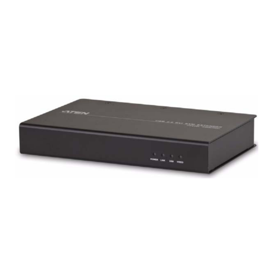
Page 12: Components
Front View Rear View Component Description LEDs The CE610L has four LEDs to indicate operating status – Power, Link, USB, and Video. Firmware Upgrade The Firmware Upgrade Port is reserved for technical Port support. If you would like to upgrade the unit’s firmware yourself, please contact your ATEN dealer. -
Page 13: Ce610R (Remote Unit) Front And Rear View
The Firmware Upgrade Port is reserved for technical Port support. If you would like to upgrade the unit’s firmware yourself, please contact your ATEN dealer. Unit to Unit Port The Cat 5e cable that connects the Local and Remote Units plugs in here. -
Page 14: Hardware Setup
Chapter 2 Hardware Setup 1. Important safety information regarding the placement of this device is provided on page 14. Please review it before proceeding. 2. Make sure that the power to all devices connected to the installation are turned off. You must unplug the power cords of any computers that have the Keyboard Power On function. - Page 15 Chapter 2. Hardware Setup 2. Screw the bracket into any convenient location on the rack. Note: These screws are not provided. We recommend that you use M5 x 12 Phillips Type I cross, recessed type screws.
-
Page 16: Installation
CE610 User Manual Installation Grounding To prevent damage to your installation it is important that all devices are properly grounded. 1. Use a grounding wire to ground both units by connecting one end of the wire to the grounding terminal, and the other end of the wire to a suitable grounded object. - Page 17 Chapter 2. Hardware Setup 3. For increased grounding protection, use STP (shielded twisted pair) cable to connect the Local and Remote Units. There are two methods that can be used: a) In addition to the eight paired wires, STP cable also contains a grounding wire.
-
Page 18: Setting Up
1. Connect the USB cable supplied with the package to the USB Type B port on the Local Unit (CE610L). Plug the other end of the cable into a USB Type A port on the local computer. 2. Connect the DVI-D cable supplied with the package to the DVI-D input port located on the Local Unit (CE610L). -
Page 19: Installation Diagram
Chapter 2. Hardware Setup Installation Diagram CE610L Rear View Local PC cable USB cable Cat 5e cable CE610R Rear View... -
Page 20: Operation
LED Display The CE610 Local and Remote Units have front panel LEDs to indicate their operating status, as shown in the tables, following: CE610L (Local Unit) and CE610R (Remote Unit) Indication Power (Green) Lights steadily to indicate that the system is receiving power. -
Page 21: Appendix
Appendix Safety Instructions General Read all of these instructions. Save them for future reference. Follow all warnings and instructions marked on the device. This product is for indoor use only. Do not place the device on any unstable surface (cart, stand, table, etc.). If the device falls, serious damage will result. - Page 22 CE610 User Manual If an extension cord is used with this device make sure that the total of the ampere ratings of all products used on this cord does not exceed the extension cord ampere rating. Make sure that the total of all products plugged into the wall outlet does not exceed 15 amperes.
-
Page 23: Mounting
Appendix Mounting Before working on the rack, make sure that the stabilizers are secured to the rack, extended to the floor, and that the full weight of the rack rests on the floor. Install front and side stabilizers on a single rack or front stabilizers for joined multiple racks before working on the rack. -
Page 24: Technical Support
CE610 User Manual Technical Support International For online technical support – including troubleshooting, documentation, and software updates: http://eservice.aten.com For telephone support, Telephone Support, page iii North America Email Support support@aten-usa.com Online Troubleshooting http://www.aten-usa.com/support Technical Documentation Support Software Updates Telephone Support... -
Page 25: Specifications
Appendix Specifications Function CE610L CE610R Connectors DVI In 1 x DVI-D Female (White) DVI Out 1 x DVI-D Female (White) 1 x USB Type B Female 3 x USB Type A Female (White) (White) Power 1 x DC Jack F/W Upgrade... -
Page 26: Limited Warranty
CE610 User Manual Limited Warranty IN NO EVENT SHALL THE DIRECT VENDOR'S LIABILITY EXCEED THE PRICE PAID FOR THE PRODUCT FROM DIRECT, INDIRECT, SPECIAL, INCIDENTAL, OR CONSEQUENTIAL DAMAGES RESULTING FROM THE USE OF THE PRODUCT, DISK, OR ITS DOCUMENTATION. The direct vendor makes no warranty or representation, expressed, implied, or statutory with respect to the contents or use of this documentation, and especially disclaims its quality, performance, merchantability, or fitness for any particular purpose.
Need help?
Do you have a question about the CE610L and is the answer not in the manual?
Questions and answers