Table of Contents
Advertisement
Quick Links
User Manual
CE-252R/L
Read this guide thoroughly and follow the installation and operation
procedures carefully in order to prevent any damage to the units and/or
any devices that connect to them.
This package contains:
1 CE-252L KVM Extender (Local Unit)
1 CE-252R KVM Extender (Remote Unit)
1 User Manual
1 User Guide
2 KVM Cables
2 Power Adapters
2 Rack Mount Kits
If anything is damaged or missing, contact your dealer.
Copyright © 2006 ATEN
ATEN and the ATEN logo are trademarks of ATEN International Co., Ltd. All rights
reserved. All other trademarks are the property of their respective owners.
®
International Co., Ltd.
Manual Part No. PAPE -1278 -100G
Printing Date: 09/2006
Advertisement
Table of Contents

Related Manuals for ATEN CE-252R


Summary of Contents for ATEN CE-252R
-
Page 1: User Manual
Copyright © 2006 ATEN International Co., Ltd. Manual Part No. PAPE -1278 -100G Printing Date: 09/2006 ATEN and the ATEN logo are trademarks of ATEN International Co., Ltd. All rights reserved. All other trademarks are the property of their respective owners. - Page 2 Note: This equipment has been tested and found to comply with the limits for a Class B digital device, pursuant to Part 15 of the FCC Rules. These limits are designed to provide reasonable protection against harmful interference in a residential installation. This equipment generates, uses and can radiate radio frequency energy, and if not installed and used in accordance with the instruction manual, may cause interference to radio...
- Page 3 OVERVIEW The CE-252R/L offers local and remote access to your KVM installation. Both (local and remote) KVM extenders support PS/2 consoles and can be located up to 300 m (1000 feet) apart. You can reliably manage a large number of computers via a KVM switch.
- Page 4 Features Built-in ASIC for greater reliability and compatibility Cat.5 cable to connect the local and remote units up to 300 meters apart Dual console operation – control the system from both the local and remote consoles Push button selection – sequential selection between local and auto mode High resolution video –...
-
Page 5: System Requirements
Although it is possible to use standard KVM cables to link computers with PS/2 type keyboard and mouse ports to the CE-252R/L, for optimal signal integrity ATEN recommends using the KVM Cables provided with this package. For best performance, use Category 5 (or better) cables to connect the CE-252 Local and Remote Units. -
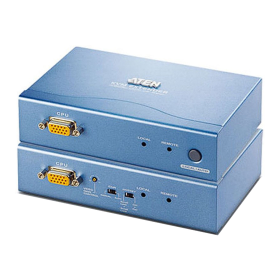
Page 6: Hardware Overview
Hardware Overview CE-252 Local Front View Description Function CPU Port KVM cable connector (KVM Port) Section Local LED On: local console active Off: remote console active Flash: neither console active Remote LED On: remote console active Off: local console active Flash: neither console active Push Button Press to choose the operating mode:... - Page 7 CE-252 Remote Front View Description Function CPU Port (KVM Port) KVM cable connector Section Manual Gain Control Use a flathead screwdriver or other similar object to manually adjust the signal gain Auto/Manual Gain Auto: the unit automatically adjusts the signal gain Selection Switch Manual: signal gain is set using the Manual Gain Control...
- Page 8 CE-252L / CE-252R Rear View Description Function Power Jack The AC Power Adapter cable connects here Keyboard/Mouse PS/2 ports for keyboard (purple) and mouse (green) Ports Remote I/O The Category 5 cable that connects the two units plugs in here...
-
Page 9: Hardware Installation
Remote I/O port on the CE-252L, then plug the other end of the Category 5 twisted pair cable into the Remote I/O port on the CE-252R. 4. Connect one of the provided power adapters into an AC source, then connect the adapter's power cable to the Power Jack on the rear of the CE-252L. -
Page 10: Installation Diagram
252R). 6. Plug the provided KVM cable into the appropriate connector on the front of the CE-252R, then plug the connectors on the other end of the KVM cable into the appropriate ports on the computer system (or Console section of the KVM switch - if you are using one). -
Page 11: Hotkey Operation
Remote Console offers access to computers connected to the Remote Unit. For example, an additional computer or KVM switch connected to the Remote Unit. The CE-252R/L KVM Extender features the following two flexible computer access methods: Hotkey Operation and Auto Scan Mode. -
Page 12: Auto Scan Mode (Asm)
Auto Scan Mode (ASM) The Auto Scan feature automatically toggles the KVM focus between the Local and Remote Units at regular intervals. As a result, any computers connected to each can be monitored without user intervention. The default time interval is 5 seconds. To invoke Auto Scan Mode do the following: Press and release the Left Shift key;... -
Page 13: Using Gain Controls
10 secs 20 secs Using Gain Controls After installing the CE-252R/L, you can adjust the strength of the video signal (Gain). There are two available Gain controls: Automatic and Manual. Select the Automatic Gain slide switch on the Remote Unit to let CE-252R/L adjust the video signal strength. -
Page 14: Specifications
Specifications Function CE-252L CE-252R Computer Connections Port Selection 1 x Pushbutton Connectors Console Keyboard 1 x 6-pin Mini-DIN Female (Purple) Port Video 1 x HDB-15 Female (Blue) Mouse 1 x 6-pin Mini-DIN Female (Green) KVM Port 1 x SPHD-15 Female (Yellow) -
Page 15: Vga Pin Assignments
VGA Pin Assignments Signal Signal Signal Red Video Analog Ground Green Video Analog Ground Blue Video Analog Ground Horizontal Sync Vertical Sync Ground Ground TP WIRING DIAGRAM PAIR 3 PAIR 2 PAIR 1 PAIR 4 1 2 3 4 5 6 W-O O W-G Bl W-Bl G W-Br Br JACK POSITIONS T568B... -
Page 16: Getting Help
Getting Help If you need to contact ATEN technical support with a problem, visit our website at www.aten.com. Limited Warranty IN NO EVENT SHALL THE DIRECT VENDOR'S LIABILITY EXCEED THE PRICE PAID FOR THE PRODUCT FROM THE DIRECT, INDIRECT, SPECIAL, INCIDENTAL OR CONSEQUENTIAL DAMAGES RESULTING FROM THE USE OF THE PRODUCT, DISK OR ITS DOCUMENTATION.
Need help?
Do you have a question about the CE-252R and is the answer not in the manual?
Questions and answers