
Related Manuals for Phoenix Model AT6-TEXAN


Summary of Contents for Phoenix Model AT6-TEXAN
-
Page 1: Instruction Manual
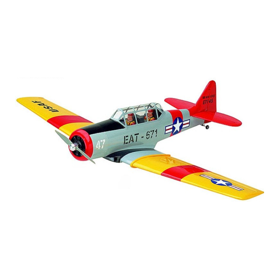
Instruction Manual at6-TEXAN Wingspan : 1507 mm (59.33 in) Length : 1250 mm (49.21 in) Weight : 3300gr - 3600gr Engine : 61 two stroke / 71 four stroke Radio : 6 channel / 6 servo... -
Page 2: Kit Contents
KIT CONTENTS: We have organized the parts as they come out of the box for better identification during assembly. We recommend that you regroup the parts in the same manner. This will ensure you have all of parts required before you begin assembly KIT CONTENTS AIR FRAME ASSEMBLIES AILERON CONTROL SYSTEM... -
Page 3: Tools And Supplies Needed
TOOLS AND SUPPLIES NEEDED INSTALLING THE AILERON SERVOS 1. Install the rubber grommets and brass eyelets • Medium C/A glue onto the aileron servo. • 30 minute epoxy • 6 minute epoxy 2. Using a modeling knife, remove the covering •... -
Page 4: Installing The Aileron Linkage
INSTALLING THE AILERON LINKAGE 5. Place the aileron servo tray / hatch into the servo box on the bottom of the wing and drill 1. Working with the aileron linkage for now, thread 1,6mm pilot holes through the tray and the one nylon clevis at least 14 turns onto one of servo box for each of the four mounting screws. -
Page 5: Joining The Wing Halves
9. Repeat step #1 - #8 to install the second aileron linkage. After both linkages are completed, connect both of the aileron servo leads using a Y-harness you have purchased separately. JOINING THE WING HALVES 1. Mix a generous amount of 30 minute epoxy. Working with only one wing half for now, apply a thin layer of epoxy inside the plywood dihedral brace box and to only half of the... - Page 6 2. Remove the covering. 6. Install the cover for the gear. 7. Secure the wheel. 3. Glue the C.A 8. Install the adjustable servo connector to the servo arm of the servo retract gear. 4. Attach the metal rod to the retract gear. Metal pushrod Clevis 9.
-
Page 7: Installing The Horizontal Stabilizer
INSTALLING THE HORIZONTAL STABILIZER 1. Using a modeling knife, cut away the covering from the fuselage for the stabilizer and remove it. 2. Place the horizontal stabilizer to the fuselage. Retract and the gear is opened. 3. Check the fit of the horizontal stabilizer in its slot. -
Page 8: Installing The Vertical Stabilizer
7. When you are sure that everything is aligned correctly, mix up a generous amount of 30 minute epoxy. Apply a thin layer to the bottom of the stabilizer mounting area and to the stabilizer mounting platform sides in the fuselage. -
Page 9: Installing The Tail Wheel
INSTALLING THE TAIL WHEEL 3. Using a triangle, check to ensure that the vertical stabilizer is aligned 90 degree to the horizontal stabilizer. 1. Using the knife cut away the wood from the bottom of the rudder and slide the two nylon clasps into the slot. -
Page 10: Installing The Engine
down thrust right thrust FUEL TANK INSTALLING THE THROTTLE PUSHROD HOUSING INSTALLING THE STOPPER ASSEMBLY 1. Place the engine into the engine mount and align it properly with the front of the cowling. 1. The stopper has been pre-assembled at the The distance from the firewall to the front of the factory. -
Page 11: Installing The Elevator Pushrod
7. Using a modeling knife, cut 3 lengths of fuel line Elevator servo 150mm long. Connect 2 lines to the 2 vent tubes and 1 line to the fuel pickup tube in the stopper. 8. Feed three lines through the fuel tank compartment and through the pre-drilled hole in the firewall. -
Page 12: Installing The Rudder Pushrod
8. Connect the two elevator pushrod using the 5. The control horn should be mounted on the left metal domino. side of the rudder at the leading edge, in line with the rudder pushrod. 9. Locate one nylon servo arm, and using wire cutters, remove all but one of the arms. -
Page 13: Mounting The Cowl
MOUNTING THE COWL 1. Remove the muffler and needle valve assembly from the engine. Slide the fiberglass cowl over the engine. 2. Measure and mark the locations to be cut out for engine head clearance, needle valve, muffler,. Remove the cowl and make these cutouts using a rotary tool with a cutting disc and a rotary sanding drum attachment. -
Page 14: Installing The Receiver And Battery
INSTALLING THE RECEIVER AND BATTERY FINAL ASSEMBLY INSTALLING THE SPINNER 1. Plug the servo leads and the switch lead into the receiver. You may want to plug an aileron extension into the receiver to make plugging in Install the spinner back-plate, propeller and the aileron servo lead easier when you are spinner cone. -
Page 15: Control Throws
BALANCING CONTROL THROWS 1. It is critical that your airplane be balanced correctly. 1. We highly recommend setting up a plane using the Improper balance will cause your plane to lose control throws listed. control and crash. 2. The control throws should be measured at the widest THE CENTER OF GRAVITY IS LOCATED 130mm point of each control surface. - Page 16 I/C FLIGHT GUIDELINES Operate the control sticks on the When ready to fly, first extend the transmitter and check that the control transmitter aerial. surfaces move freely and in the ALWAYS land the model INTO the CORRECT directions. wind, this ensures that the model lands at the slowest possible speed.
Need help?
Do you have a question about the AT6-TEXAN and is the answer not in the manual?
Questions and answers