Table of Contents
Advertisement
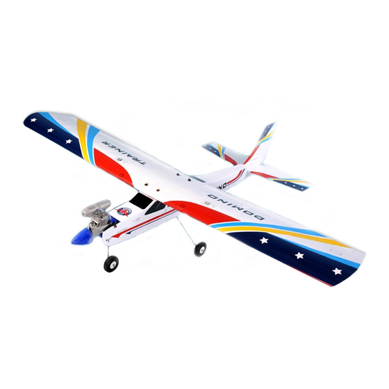
I n s t r u c t i o n M a n u a l
Specification:
Specification:
Wingspan : 158 cm (62 inch)
Length
: 122 cm (48 inch)
Weigth
: 2400 gr
Engine
: 40 - 46 two stroke
Radio
: 4 channels / 4 servo
We wish you many enjoyable flights with your plane and one again thank you for your choosing a Phoenix Model products.
Advertisement
Table of Contents

Subscribe to Our Youtube Channel
Related Manuals for Phoenix Model Domino


Summary of Contents for Phoenix Model Domino
- Page 1 : 122 cm (48 inch) Weigth : 2400 gr Engine : 40 - 46 two stroke Radio : 4 channels / 4 servo We wish you many enjoyable flights with your plane and one again thank you for your choosing a Phoenix Model products.
-
Page 2: Kit Contents
Instruction Manual DOMINO KIT CONTENTS: We have organized the parts as they come out of the box for better identification during assembly. We recommend that you regroup the parts in the same manner. This will ensure you have all of parts required before you begin assembly. - Page 3 Instruction Manual DOMINO Installing the aileron servo and linkage. Installing the aileron servo and linkage. Remove the covering from the aileron servo box (at the Install and secure the aileron servo. bottom of the wing). Pull the servo lead out.
-
Page 4: Joining The Wing Halves
Instruction Manual DOMINO Bend “L” the metal pushrod. Insert the nylon clasp to the metal rod. Make the same way for the second aileron servo. Joining the wing halves Joining the wing halves Secure the wing to the fuselage using the plastic screws. - Page 5 Instruction Manual DOMINO Remove the covering from the vertical. Secure the vertical onto the horizontal. Slide vertical and horizontal into the fuselage. Secure the horizontal to the fuselage. Installing the elevator and rudder pushrod. Installing the elevator and rudder pushrod.
- Page 6 Instruction Manual DOMINO Attach the clevis to the elvator pushrod. Insert the elevator pushrod into the fuselage. Attach the clevis to the control horn. Make same way for the second elevator pushrod. Install the nylon control horn onto the rudder.
-
Page 7: Installing The Landing Gear
Instruction Manual DOMINO Installing the landing gear. Installing the landing gear. The landing gear. Install the collar. Install the wheel. Remove the covering on the fuselage. Secure the landing gear. The nose gear. Install the wheel. Install the nose gear and secure it. - Page 8 Instruction Manual DOMINO Installing the servo of the rudder, the elevator and fuel tank. Installing the servo of the rudder, the elevator and fuel tank. Install the rudder servo. Install the metal connector. Cut and bend "L" the rudder pushrod.
-
Page 9: Installing The Engine
Instruction Manual DOMINO Secure the stopper to the tank. Slide the fuel tank into the fuselage. Install the silicon tubes. Installing the engine Installing the engine Attach the throttle rod into the arm of the carburator. Install the engine and secure it. -
Page 10: Installing The Throttle Servo
Instruction Manual DOMINO Installing the throttle servo. Installing the throttle servo. Install the throttle servo. Install the metal connector. Secure the servo arm. Attach the throttle rod into the metal connector and secure it. Cut away the throttle rod if neccessary. - Page 11 Instruction Manual DOMINO Low throttle stick position. Mid throttle stick position. High throttle stick position. Installing the switch, spinner and propller. Installing the switch, spinner and propller. Switch Receiver Install the switch. Install the propller. Install the spinner.
-
Page 12: Control Throws
Instruction Manual DOMINO BALANCING CONTROL THROWS 1. It is critical that your airplane be balanced correctly. We highly recommend setting up a plane using the Improper balance will cause your plane to lose control throws listed. control and crash. 2. The control throws should be measured at the widest THE CENTER OF GRAVITY IS LOCATED 75mm point of each control surface.
Need help?
Do you have a question about the Domino and is the answer not in the manual?
Questions and answers