Table of Contents
Advertisement
Quick Links
Advertisement
Chapters
Table of Contents

Related Manuals for IEI Technology AFOLUX AFL-315AW/B


Summary of Contents for IEI Technology AFOLUX AFL-315AW/B
- Page 1 AFOLUX Kiosk Application Series Page i...
- Page 2 AFOLUX Kiosk Application Series Revision Date Version Changes 2008-04 1.00 Initial release Page ii...
- Page 3 AFOLUX Kiosk Application Series Copyright COPYRIGHT NOTICE The information in this document is subject to change without prior notice in order to improve reliability, design and function and does not represent a commitment on the part of the manufacturer. In no event will the manufacturer be liable for direct, indirect, special, incidental, or consequential damages arising out of the use or inability to use the product or documentation, even if advised of the possibility of such damages.
-
Page 4: Manual Conventions
AFOLUX Kiosk Application Series Manual Conventions WARNING! Warnings appear where overlooked details may cause damage to the equipment or result in personal injury. Warnings should be taken seriously. Warnings are easy to recognize. The word “warning” is written as “WARNING,” both capitalized and bold and is followed by text. - Page 5 AFOLUX Kiosk Application Series CAUTION: This is an example of a caution message. Failure to adhere to cautions messages may result in permanent damage to the AFOLUX AFL-315 series. Please take caution messages seriously. NOTE: These messages inform the reader of essential but non-critical information. These messages should be read carefully as any directions or instructions contained therein can help avoid making mistakes.
- Page 6 AFOLUX Kiosk Application Series Packing List NOTE: If any of the components listed in the checklist below are missing, please do not proceed with the installation. Contact the IEI reseller or vendor you purchased the AFOLUX AFL-315 series from or contact an IEI sales representative directly.
-
Page 7: Table Of Contents
AFOLUX Kiosk Application Series Table of Contents INTRODUCTION..................... 1 1.1 AFOLUX AFL-315AB/W S PC O ......... 2 ERIES ANEL VERVIEW 1.1.1 Features and Model Variations................3 1.1.2 Applications ....................... 3 1.1.3 Standard Features ....................3 1.2 E ....................4 XTERNAL VERVIEW 1.2.1 General Description................... - Page 8 AFOLUX Kiosk Application Series 2.4.3 External USB Connectors ................20 2.4.4 Keyboard and Mouse Connectivity ..............20 2.5 AFOLUX AFL-315 F ................21 RONT 2.5.1 Monitor ......................21 2.5.2 Touch-Screen Module..................22 2.6 G ........................ 22 RAPHICS ® 2.6.1 Intel 945G Integrated Graphics Media Accelerator 950.......
- Page 9 AFOLUX Kiosk Application Series 4.3 P .................. 39 REINSTALLED OMPONENTS 4.4 I ............. 39 NSTALLATION AND ONFIGURATION TEPS 4.5 R ................... 40 EMOVING THE ANEL 4.6 CF C ..................41 NSTALLATION 4.7 J ....................42 UMPER ETTINGS 4.7.1 Access the Jumpers ..................43 4.7.2 Preconfigured Jumpers ..................
- Page 10 AFOLUX Kiosk Application Series 5.5.2 CF Card Replacement..................80 5.5.3 DIMM Module Replacement................82 5.5.4 CPU Replacement.................... 84 5.5.5 Cooling Fan Replacement................88 5.6 R ..................90 EINSTALLING THE COVERS AMI BIOS SETUP....................91 6.1 I ......................92 NTRODUCTION 6.1.1 Starting Setup....................92 6.1.2 Using Setup ......................
- Page 11 AFOLUX Kiosk Application Series 7.1 IEI I SMM)......... 144 NTELLIGENT YSTEM ANAGEMENT ODULE 7.1.1 What is iSMM....................144 7.1.2 iSMM Features....................144 7.2 COM P LED I ................145 NDICATORS SYSTEM SPECIFICATIONS ................147 A.1 M ................148 OTHERBOARD PECIFICATIONS A.2 P .................
- Page 12 AFOLUX Kiosk Application Series WATCHDOG TIMER ..................171 HAZARDOUS MATERIALS DISCLOSURE ........... 175 F.1 H IPB P AZARDOUS ATERIAL ISCLOSURE ABLE FOR RODUCTS ERTIFIED AS HS C 2002/95/EC W ........176 OMPLIANT NDER ITHOUT ERCURY INDEX..........................179 Page xii...
- Page 13 AFOLUX Kiosk Application Series List of Figures Figure 1-1: AFOLUX AFL-315AW .................2 Figure 1-2: AFL-315 Front View ...................5 Figure 1-3: AFL-315 Rear View..................6 Figure 1-4: AFL-315 I/O Interface Connector Panel ...........7 Figure 1-5: AFL-315 Top View ..................7 Figure 1-6: AFL-315 Bottom View ................7 Figure 1-7: AFL-315 Side Views ...................8 Figure 2-1: AFL-315 Front Panel Dimensions (mm)..........14 Figure 2-2: AFL-315 Side Panel Dimensions (mm ...........15...
- Page 14 AFOLUX Kiosk Application Series Figure 4-1: Rear Panel Retention Screws..............40 Figure 4-2: HDD Bracket Retention Screws .............41 Figure 4-3: CF Card Insert ..................42 Figure 4-4: Jumper Locations..................42 Figure 4-5: Clear CMOS Jumper ................45 Figure 4-6: COM1, COM4, COM5 and COM6 Pin 9 Setting Jumper Location..46 Figure 4-7: COM6 RX Function Select Jumper Location ........47 Figure 4-8: COM6 TX Function Select Jumper Pinout Locations ......48 Figure 4-9: COM6 RS-232/422/485 Serial Port Select Jumper Location ....50...
- Page 15 AFOLUX Kiosk Application Series Figure 5-3: Back Cover Retention Screws..............75 Figure 5-4: Metal Enclosure Retention Screws ............76 Figure 5-5: Peripheral Interface Connector Screwdrivers ........77 Figure 5-6: Peripheral Connector Retention Screws..........77 Figure 5-7: Processor and DIMM Housing..............78 Figure 5-8: HDD Bracket Retention Screws .............79 Figure 5-9: HDD Retention Screws................80 Figure 5-10: Locate the CF Card................81 Figure 5-11: DIMM Socket Location................83...
- Page 16 AFOLUX Kiosk Application Series List of Tables Table 1-1: AFL-315 Series System Specifications ...........11 Table 4-1: Jumpers......................43 Table 4-2: Preconfigured Jumpers ................44 Table 4-3: Clear CMOS Jumper Settings..............45 Table 4-4: COM1, COM4, COM5 and COM6 Pin 9 Setting Jumper Settings ..46 Table 4-5: COM6 RX Function Select Jumper Settings ...........47 Table 4-6: COM6 TX Function Select Jumper Settings ...........48 Table 4-7: COM6 RS-232/422/485 Serial Port Select Jumper Settings....49...
-
Page 17: Introduction
AFOLUX Kiosk Application Series Chapter Introduction Page 1... -
Page 18: Afolux Afl-315Ab/W Series Flat Panel Pc Overview
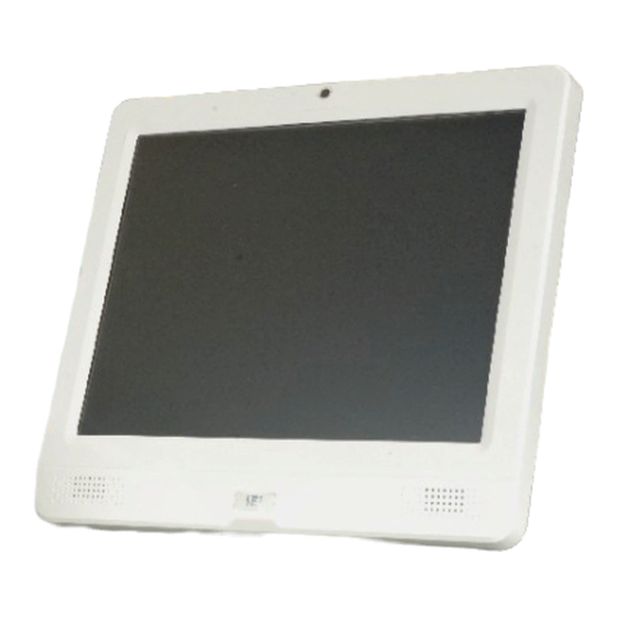
AFOLUX Kiosk Application Series 1.1 AFOLUX AFL-315AB/W Series Flat Panel PC Overview Figure 1-1: AFOLUX AFL-315AW The AFOLUX315AB and AFOLUX315W (AFL-315) are Intel® Core™2 Duo or Intel® Celeron® D powered flat panel PCs with a rich variety of functions and peripherals. Both AFL-315 models are designed for easy and simplified integration in to kiosk and point-of-sales (POS) applications. -
Page 19: Features And Model Variations
AFOLUX Kiosk Application Series A white or black AFL-315 is available to ensure the AFL-315 system blends into its operational environment. 1.1.1 Features and Model Variations There are two models in the AFL-315 series, the AFL-315AB-945/WT-R/1G and the AFL-315AW-945/WT-R/1G. Both models feature the following: Intel®... -
Page 20: External Overview
AFOLUX Kiosk Application Series Eight USB 2.0 ports Watchdog timer that triggers a system reset if the system hangs for some reason iSMM system health supervision API to track the system status Built-in stereo speakers Bluetooth functionality Touch screen option Wireless LAN connectivity IP 64 compliant front panel AT or ATX power mode... -
Page 21: Rear Panel
AFOLUX Kiosk Application Series Figure 1-2: AFL-315 Front View 1.2.3 Rear Panel The rear panel provides access to retention screw holes that support the wall mounting and to the I/O interface panel that enable connection to a wide range of external peripheral devices. -
Page 22: I/O Interface Panel
AFOLUX Kiosk Application Series Figure 1-3: AFL-315 Rear View 1.2.4 I/O Interface Panel The I/O interface panel located on the rear side of the AFL-315 (see Figure 1-3 above) has the following I/O interface connectors: 1 x 24 V DC Out connector 1 x 12 V or 24 V DC In connector 8 x USB 2.0 connectors 1 x LAN connector... -
Page 23: Top Panel And Bottom Panel
AFOLUX Kiosk Application Series The external I/O interface connector panel is shown in Figure 1-4. Figure 1-4: AFL-315 I/O Interface Connector Panel 1.2.5 Top Panel and Bottom Panel The top panel and side panels of AFOLUX AFL-315 series provides access to slots that support panel mount and rack mount (Figure 1-5 and Figure 1-6). -
Page 24: Rear Panel Connectors
AFOLUX Kiosk Application Series 1.2.6 Rear Panel Connectors The side panels of the AFL-315 panel PC have ventilation vents that cool the interior of the system. The left panel also has a power switch near the bottom. See Figure 1-7. Figure 1-7: AFL-315 Side Views 1.3 Internal Overview The AFOLUX AFL-315 has the following components installed internally:... -
Page 25: Specifications
AFOLUX Kiosk Application Series 1.4 Specifications 1.4.1 Preinstalled Hardware Components The AFOLUX AFL-315 series flat panel PC has the following preinstalled components: 1 x Motherboard 1 x TFT LCD screen 1 x Touch screen 1 x Inverter 1 x Wireless LAN module 1 x DDR memory module 1 x Bluetooth module 1 x AT/ATX switch... - Page 26 AFOLUX Kiosk Application Series 1.8 GHz Intel® Dual Core desktop (E2160) or others Graphics Memory Controller Intel® 945G Memory One 1.0 GB DDR2 SDRAM DIMM pre-installed Brightness (cd/m CF Type II Watchdog Timer Software Programmable supports 1 sec. ~ 255 sec. system reset Audio AMP 1.5 W + AMP 1.5 W (built-in stereo speakers)
-
Page 27: Table 1-1: Afl-315 Series System Specifications
AFOLUX Kiosk Application Series IP level (front panel) IP 64 CE, FCC and CCC Safety UL and CB Touch Screen Resistive Type 5-wire (touch controller IC is on board) Power Adapter (ACE-D825AH) 252 W Input: 90 VAC ~ 264 VAC @ 50 Hz / 60 Hz Output: 12 VDC at 15 A, 24 VDC at 3 A Power Consumption 102 W... - Page 28 AFOLUX Kiosk Application Series THIS PAGE IS INTENTIONALLY LEFT BLANK Page 12...
-
Page 29: Detailed Specifications
AFOLUX Kiosk Application Series Chapter Detailed Specifications Page 13... -
Page 30: Dimensions
AFOLUX Kiosk Application Series 2.1 Dimensions The following sections provide detailed schematics and information on the dimensions of the AFL-315. 2.1.1 Front Panel Dimensions Front panel dimensions are shown in Figure 2-1 and listed below. 364.4 mm Width: 323.4 mm Height: Figure 2-1: AFL-315 Front Panel Dimensions (mm) 2.1.2 Side Dimensions... -
Page 31: Top And Bottom Panel Dimensions
AFOLUX Kiosk Application Series 13.4 mm Screen Protrusion (Top): 12.9 mm Screen Protrusion (Bottom): Figure 2-2: AFL-315 Side Panel Dimensions (mm 2.1.3 Top and Bottom Panel Dimensions Top and bottom panel dimensions are shown in Figure 2-3 and listed below. 15.1 mm Screen Protrusion (Right): 15.1 mm... -
Page 32: Intel® Desk-Top Processor Support
AFOLUX Kiosk Application Series 2.2 Intel® Desk-Top Processor Support An E2160 Intel® LGA775 Pentium® Dual-Core desktop processor is installed in the system. The processor has a CPU speed of 1.8 GHz and an 800 MHz front side bus (FSB). The processor also comes with a 1.0 MB L2 cache and a 1.8 GHz L2 cache speed. The processor is shown in Figure 2-4 below. -
Page 33: Motherboard Components
AFOLUX Kiosk Application Series 2.3 Motherboard Components The following sections describe some of the features on the motherboard. 2.3.1 Memory Support 2.3.1.1 Installed Memory One 240-pin 1.0 GB DDR2 SDRAM DIMM is installed in the AFL-315 and controlled by the Intel® 945G GMCH installed on the internal motherboard. 2.3.1.2 Additional Memory The Intel®... -
Page 34: Storage Capacity
AFOLUX Kiosk Application Series 2.3.2 Storage Capacity The AFL-315 comes with a preinstalled 160 GB 150 Mbps SATA hard disk drive. The system can also support an easily installed CompactFlash® Type II (CF Type II) memory disk. 2.4 External Peripheral Interface Connectors The following section describes the external peripheral interface connectors on the rear panel of the subsystem. -
Page 35: Lan Connectivity
AFOLUX Kiosk Application Series Two of the serial ports (COM1 and COM2) are interfaced to the ITE IT8712 super, through the low pin count (LPC) bus to the ICH7 Southbridge. The remaining two serial ports (COM3 and COM4) are connected to the ICH7 LPC bus through a Fintek serial port controller. -
Page 36: External Usb Connectors
AFOLUX Kiosk Application Series Automatic MDI crossover function PCIe v1.0a 10/100/1000BASE-T full/half-duplex MAC Wake on LAN support meeting the ACPI requirements Statistics for SNMP MIB II, Ethernet-like MIB, and Ethernet MIB (802.3z, clause 30) Serial EEPROM or serial flash support 2.4.3 External USB Connectors There are eight USB 2.0 connectors on the rear panel of the AFL-315. -
Page 37: Afolux Afl-315 Front Side
AFOLUX Kiosk Application Series Figure 2-9: Keyboard and Mouse Connector 2.5 AFOLUX AFL-315 Front Side 2.5.1 Monitor A 15” XGA AUO G150XG01 LCD screen is installed on the front of the AFOLUX AFL-315. The installed monitor has a pixel resolution of 1024 x 768 pixels. The screen is shown in Figure 2-10 below. -
Page 38: Touch-Screen Module
AFOLUX Kiosk Application Series Figure 2-10: XGA Screen 2.5.2 Touch-Screen Module A controller for the 5-wire resistive touch screen is installed on the motherboard. The sensitive touch screen is accurate, reliable and durable. 2.6 Graphics ® 2.6.1 Intel 945G Integrated Graphics Media Accelerator 950 ®... -
Page 39: Dvi Graphics
AFOLUX Kiosk Application Series Figure 2-11: VGA Connector 2.6.2 DVI Graphics The DVI connector is interfaced to the Intel® 945G graphics controller through a Chrontel CH7308B SDVO/LVDS transmitter. The Chrontel CH7308B single/dual LVDS Transmitter transmits up to 165 mega pixels per second (MP/s). The CH7308 is a display controller device, which accepts digital graphics input signals, upscales, encodes, and transmits data through an LVDS transmitter to a LCD panel. -
Page 40: Dual-Display
AFOLUX Kiosk Application Series 2.6.3 Dual-Display The system supports dual display capabilities. An additional monitor can be connected to the AFL-315 through either the VGA connector or the DVI connector described above. 2.7 Audio 2.7.1 Audio Codec ’97 Controller The Integrated AC'97 v2.3 compliant audio controller on the Intel® ICH7 Southbridge is integrated to a RealTek ALC655 audio codec. -
Page 41: System Power
AFOLUX Kiosk Application Series Figure 2-14: Stereo Speakers 2.8 System Power 2.8.1 Power Mode The system can be run in the AT power mode or the ATX power mode. Both these power modes are described below. 2.8.1.1 AT Power Mode With the AT mode selected, the power is controlled by a central power unit rather than a power switch. -
Page 42: Atx Power Mode
AFOLUX Kiosk Application Series Factory automation platform Manufacturing shop flow 2.8.1.2 ATX Power Mode With the ATX mode selected, the AFOLUX AFL-315 panel PC goes in a standby mode when it is turned off. The panel PC can be easily turned on via network or a power switch in standby mode. -
Page 43: Power Input Connector
AFOLUX Kiosk Application Series Figure 2-16: Power Connectors 2.8.3.1 Power Input Connector A standard 6-pin connector on the connector interface panel is connected to the power supply and can input 12 V or 24 V of direct current into the system. 2.8.3.2 Power Output Connector A standard 4-pin connector on the connector interface panel is provides 24 V of direct current to an external peripheral device such as a thermal printer. -
Page 44: Wireless Connections
AFOLUX Kiosk Application Series Figure 2-17: RJ-12 Connector 2.9 Wireless Connections The following section describes the wireless modules on the circuit. 2.9.1 USB Bluetooth Module An integrated Bluetooth module is connected to ICH7 chipset through the USB bus. The AFL-315 Bluetooth module enables wireless communications between the AFL-315 and various peripheral devices through a Bluetooth network. -
Page 45: Wireless Ethernet
AFOLUX Kiosk Application Series Figure 2-18: Bluetooth Module 2.9.2 Wireless Ethernet An integrate PIFA antenna on the AFOLUX AFL-315 ensures an uninterrupted wireless connection. PIFA antennas can receive high-quality, uniform signals in any location from all directions without any signal degradation or impedance and are the most efficient antennas on the market. -
Page 46: Optional Modules
AFOLUX Kiosk Application Series Figure 2-19: PIFA Antenna 2.10 Optional Modules The following sections describe the optional module available to the user. 2.10.1 GPRS Module (Optional) An optional GPRS module can be integrated into the AFL-315. The GPRS module is one of the OEM options for the AFL-315 series. -
Page 47: Figure 2-20: Internal View Of Cooling Fans
AFOLUX Kiosk Application Series Figure 2-20: Internal View of Cooling Fans The cooling fans are 50 mm x 50 mm x 10 mm in size. Fan specifications are listed in the appendix. Figure 2-21: Cooling Fan Dimensions Page 31... - Page 48 AFOLUX Kiosk Application Series THIS PAGE IS INTENTIONALLY LEFT BLANK Page 32...
-
Page 49: Unpacking
AFOLUX Kiosk Application Series Chapter Unpacking Page 33... -
Page 50: Unpacking
AFOLUX Kiosk Application Series 3.1 Unpacking To unpack the flat panel PC, follow the steps below: WARNING! The front side LCD screen has a protective plastic cover stuck to the screen. Only remove the plastic cover after the flat panel PC has been properly installed. - Page 51 AFOLUX Kiosk Application Series Quantity Item Image Standard AFOLUX AFL-315 Power adapter Power cord User manual CD and driver CD Touch pen Optional Panel mounting kit (P/N: AFLPK-315A) Wall mounting kit (P/N: AFLWK-19) Stand (P/N:STAND-A19) Page 35...
- Page 52 AFOLUX Kiosk Application Series Stand (P/N:STAND-B19) Stand (P/N: STAND-210-RS) (P/N: ARM-11-RS) (P/N: ARM-31-RS) If any of these items are missing or damaged, contact the distributor or sales representative immediately. Page 36...
-
Page 53: Installation
AFOLUX Kiosk Application Series Chapter Installation Page 37... -
Page 54: Anti-Static Precautions
AFOLUX Kiosk Application Series 4.1 Anti-static Precautions WARNING: Failure to take ESD precautions during the maintenance of the AFL-315 may result in permanent damage to the AFL-315 and severe injury to the user. Electrostatic discharge (ESD) can cause serious damage to electronic components, including the AFL-315. -
Page 55: Preinstalled Components
AFOLUX Kiosk Application Series assisting with the procedure. Anti-static Discharge: If a user open the rear panel of the flat panel PC, to configure the jumpers or plug in added peripheral devices, ground themselves first and wear and anti-static wristband. 4.3 Preinstalled Components The following components are all preinstalled. -
Page 56: Removing The Back Panel
AFOLUX Kiosk Application Series 4.5 Removing the Back Panel To access the AFL-315 internally the back panel must be removed. To remove the back panel, please follow the steps below. Remove the rear panel. Remove the seven retention screws (Figure 4-1) from Step 1: the rear panel and lift the panel off the AFL-315. -
Page 57: Cf Card Installation
AFOLUX Kiosk Application Series removed, gently lift the HDD bracket. Step 0: Figure 4-2: HDD Bracket Retention Screws 4.6 CF Card Installation The AFL-315 series has one CF Type II slot. To install the CF card, follow the instructions below. Remove the back panel. -
Page 58: Jumper Settings
AFOLUX Kiosk Application Series Figure 4-3: CF Card Insert Reinstall the HDD bracket and the rear panel. Make sure the HDD bracket Step 3: and the rear panel are properly secured with the previously removed retention screws.Step 0: 4.7 Jumper Settings NOTE: A jumper is a metal bridge used to close an electrical circuit. -
Page 59: Access The Jumpers
AFOLUX Kiosk Application Series The following jumpers can be found on the motherboard installed in the AFL-315. Before the AFL-315 is installed, the jumpers must be set in accordance with the desired configuration. The jumpers on the AFL-315 motherboard are listed in Table 4-1. Description Label Type... -
Page 60: Clear Cmos Jumper
AFOLUX Kiosk Application Series The following jumpers are preconfigured for the AFL-315. Users should no change these jumpers. Jumper Name Label Type LVDS voltage selection 3-pin header Touch Screen Select 4-pin header Panel Type and Resolution 10-pin header Table 4-2: Preconfigured Jumpers 4.7.3 Clear CMOS Jumper Jumper Label: Jumper Type:... -
Page 61: Com1 To Com6 Pin 9 Select
AFOLUX Kiosk Application Series AT Power Select Description OPEN Keep CMOS Setup Default SHORT Clear CMOS Setup Table 4-3: Clear CMOS Jumper Settings The location of the clear CMOS jumper is shown in Figure 4-5 below. Figure 4-5: Clear CMOS Jumper 4.7.4 COM1 to COM6 Pin 9 Select Jumper Label: JP5, JP6, JP7 and JP8... -
Page 62: Com6 Rx Function Select Jumper
AFOLUX Kiosk Application Series as either +5 V or +12 V. Pin 9 on the COM4 and COM6 DB-9 connectors can be set as either +12 V or as the ring (RI) signal. The COM1, COM4, COM5 and COM6 Pin 9 Setting jumper selection options are shown in Table 4-4. -
Page 63: Com6 Tx Function Select Jumper
AFOLUX Kiosk Application Series Jumper Settings: See Table 4-5 Jumper Location: See Figure 4-7 The COM6 RX Function Select jumper sets the communication protocol used by the RX serial communications port COM6 as RS-232, RS-422 or RS-485. The COM6 RX Function Select jumper settings are shown in Table 4-7. -
Page 64: Figure 4-8: Com6 Tx Function Select Jumper Pinout Locations
AFOLUX Kiosk Application Series Jumper Type: 6-pin header Jumper Settings: See Table 4-6 Jumper Location: See Figure 4-8 The COM6 TX Function Select jumper configures the TX pin on COM6 serial port connector as RS-422 as an RS-485. The COM6 TX Function Select jumper selection options are shown in Table 4-6. -
Page 65: Com6 Rs-232/422/485 Serial Port Select Jumper
AFOLUX Kiosk Application Series 4.7.7 COM6 RS-232/422/485 Serial Port Select Jumper Jumper Label: Jumper Type: 12-pin header (four 3-pin headers combined) Jumper Settings: See Table 4-7 Jumper Location: See Figure 4-9 The COM6 RS-232/422/485 Serial Port Select jumper sets the communication protocol used by the second serial communications port (COM6) as RS-232, RS-422 or RS-485. -
Page 66: At/Atx Mode Selection
AFOLUX Kiosk Application Series Figure 4-9: COM6 RS-232/422/485 Serial Port Select Jumper Location 4.8 AT/ATX Mode Selection AT and ATX power modes can both be used on the AFOLUX AFL-315 flat panel PC. The selection is made through an AT/ATX switch on the aluminum chassis inside the plastic back cover (Figure 4-11). -
Page 67: Figure 4-10: Back Cover Retention Screws
AFOLUX Kiosk Application Series Figure 4-10: Back Cover Retention Screws Locate the AT/ATX switch on the aluminum chassis (Figure 4-11). Step 2: Page 51... -
Page 68: Mounting The System
AFOLUX Kiosk Application Series Figure 4-11: AT/ATX Switch Adjust the AT/ATX switch. The default mode is ATX mode with the switch being Step 3: pushed down. (Figure 4-11)Step 0: 4.9 Mounting the System WARNING! When mounting the flat panel PC onto an arm, onto the wall or onto a panel, it is better to have more than one person to help with the installation to make sure the panel PC does not fall down and get damaged. -
Page 69: Wall Mounting
AFOLUX Kiosk Application Series Rack mounting The four mounting methods are described below. 4.9.1 Wall Mounting To mount the flat panel PC onto the wall, please follow the steps below. Select the location on the wall for the wall-mounting bracket. Step 1: Carefully mark the locations of the four screw holes in the bracket on the wall. -
Page 70: Figure 4-13: Chassis Support Screws
AFOLUX Kiosk Application Series Align the mounting screws on the monitor rear panel with the mounting holes on Step 7: the bracket. Carefully insert the screws through the holes and gently pull the monitor Step 8: downwards until the monitor rests securely in the slotted holes (Figure 4-13). Ensure that all four of the mounting screws fit snuggly into their respective slotted holes. -
Page 71: Panel Mounting
AFOLUX Kiosk Application Series Figure 4-14: Secure the Panel PC 4.9.2 Panel Mounting To mount the AFOLUX AFL-315 series flat panel PC into a panel, please follow the steps below. Select the position on the panel to mount the flat panel PC. Step 1: Cut out a section from the panel that corresponds to the rear panel dimensions Step 2:... -
Page 72: Figure 4-15: Afl-315 Panel Opening
AFOLUX Kiosk Application Series Figure 4-15: AFL-315 Panel Opening Slide the flat panel PC through the hole until the frame is flush against the panel. Step 3: Insert the panel mounting clamps into the pre-formed holes along the edges of Step 4: the chassis, behind the frame. -
Page 73: Arm Mounting
AFOLUX Kiosk Application Series 4.9.3 Arm Mounting The AFOLUX AFL-315 series is VESA (Video Electronics Standards Association) compliant and can be mounted on an arm with a 100mm interface pad. To mount the AFOLUX AFL-315 series on an arm, please follow the steps below. The arm is a separately purchased item. -
Page 74: Cabinet And Rack Installation
AFOLUX Kiosk Application Series Figure 4-17: AFL-315 Arm Mounting Retention Screw Holes Secure the flat panel PC to the interface pad by inserting four retention screws Step 4: through the bottom of the mounting arm interface pad and into the flat panel PC. Step 0: 4.9.4 Cabinet and Rack Installation The AFL-315 series flat panel PC can be installed into a cabinet or rack. -
Page 75: Figure 4-18: The Rack/Cabinet Bracket
AFOLUX Kiosk Application Series rack/cabinet bracket until the frame is flush against the front of the bracket (Figure 4-18). Figure 4-18: The Rack/Cabinet Bracket Insert the rack mounting clamps into the pre-formed holes along the edges of Step 2: the flat panel PC, behind the ABS/PC plastic frame. Tighten the screws that pass through the rack mounting clamps until the plastic Step 3: caps at the front of all the screws are firmly secured to the bracket (Figure 4-19). -
Page 76: Bottom Panel Connectors
AFOLUX Kiosk Application Series cabinet (Figure 4-20). Figure 4-20: Install into a Rack/Cabinet Once the flat panel PC with the attached rack/cabinet bracket has been properly Step 5: inserted into the rack or cabinet, secure the front of the rack/cabinet bracket to the front of the rack or cabinet (Figure 4-20).Step 0: 4.10 Bottom Panel Connectors... -
Page 77: Serial Device Connection
AFOLUX Kiosk Application Series Figure 4-21: LAN Connection Insert the LAN cable RJ-45 connector. Once aligned, gently insert the LAN Step 3: cable RJ-45 connector into the onboard RJ-45 connector. Step 0: 4.10.2 Serial Device Connection The AFOLUX AFL-315 Series has four male DB-9 connectors on the bottom panel for serial devices to be connected. -
Page 78: Figure 4-22: Serial Device Connector
AFOLUX Kiosk Application Series Figure 4-22: Serial Device Connector Secure the connector. Secure the serial device connector to the external Step 3: interface by tightening the two retention screws on either side of the connector. Step 0: Page 62... -
Page 79: Usb Device Connection
AFOLUX Kiosk Application Series 4.10.3 USB Device Connection There are four external USB 2.0 connectors. All connectors are perpendicular to the AFOLUX AFL-315 Series. To connect a USB 2.0 or USB 1.1 device, please follow the instructions below. Located the USB connectors. The locations of the USB connectors are shown Step 1: in Chapter 2. -
Page 80: Webcam Driver Installation
AFOLUX Kiosk Application Series 4.11 Webcam Driver Installation To install the webcam driver, please follow the instructions below. Run the CD that came with the AFL-315 on the AFL-315. Step 1: Locate the Webcam installation program. Step 2: Click the webcam driver installation icon Step 3: The program prepares for installation. -
Page 81: Figure 4-25: Driver Installation Starting Screen
AFOLUX Kiosk Application Series Figure 4-25: Driver Installation Starting Screen Click N in Figure 4-25 to continue. Step 6: The program is ready for installation. See Figure 4-26. Step 7: Page 65... -
Page 82: Figure 4-26: Ready To Install Driver
AFOLUX Kiosk Application Series Figure 4-26: Ready to Install Driver Click I in Figure 4-26 to continue. Step 8: NSTALL The driver is then installed. See Figure 4-27. Step 9: Page 66... -
Page 83: Figure 4-27: Driver Installs
AFOLUX Kiosk Application Series Figure 4-27: Driver Installs Click Y when asked for digital signature affirmation. See Figure 4-28. Step 10: Page 67... -
Page 84: Figure 4-28: Confirm Digital Signature
AFOLUX Kiosk Application Series Figure 4-28: Confirm Digital Signature The installation process is complete See Figure 4-29. Click F to confirm. Step 11: INISH Page 68... -
Page 85: Figure 4-29: Installation Complete
AFOLUX Kiosk Application Series Figure 4-29: Installation Complete Restart the computer. See Figure 4-30. Step 12: Step 0: Page 69... -
Page 86: Figure 4-30: Restart The Computer
AFOLUX Kiosk Application Series Figure 4-30: Restart the computer. Page 70... -
Page 87: System Maintenance
AFOLUX Kiosk Application Series Chapter System Maintenance Page 71... -
Page 88: System Maintenance Introduction
AFOLUX Kiosk Application Series 5.1 System Maintenance Introduction If the components of the AFOLUX AFL-315 series fail they must be replaced. Components that can be replaced include: CF Module SATA HDD Cooling Fans Camera Blue tooth module Wireless LAN module DIMM module Please contact the system reseller or vendor to purchase the replacement parts. -
Page 89: Turn Off The Power
AFOLUX Kiosk Application Series material. During the time the board is handled, frequently touch any conducting materials that are connected to the ground. Use an anti-static pad: When configuring the AFL-315, place it on an antic-static pad. This reduces the possibility of ESD damaging the AFL-315. Only handle the edges of the PCB:-: When handling the PCB, hold the PCB by the edges. -
Page 90: Figure 5-1: Rear Panel Retention Screws (Back)
AFOLUX Kiosk Application Series Figure 5-1: Rear Panel Retention Screws (Back) Remove the retention screws from the bottom. Remove the two retention Step 4: screws from the bottom surface of the back panel. See Figure 5-2. Figure 5-2: Rear Panel Retention Screws (Bottom) Remove the rear panel. -
Page 91: Removing The Plastic Cover
AFOLUX Kiosk Application Series 5.4.2 Removing the Plastic Cover To access the AT/ATX selection switch, the white/black plastic cover must be removed. To do this,follow the steps below. Follow all anti-static procedures. See Section 5.2. Step 1: Turn off the power. See Section 5.3. Step 2: Remove the back panel. -
Page 92: Figure 5-4: Metal Enclosure Retention Screws
AFOLUX Kiosk Application Series Follow all anti-static procedures. See Section 5.2. Step 1: Turn off the power. See Section 5.3. Step 2: Remove the back panel. See Section 5.4.1. Step 3: Remove the plastic cover. See Section 5.4.2. Step 4: Remove the retention screws. -
Page 93: Figure 5-5: Peripheral Interface Connector Screwdrivers
AFOLUX Kiosk Application Series Figure 5-5: Peripheral Interface Connector Screwdrivers Figure 5-6: Peripheral Connector Retention Screws Remove the enclosure. Pull the metal enclosure up gently.Remember the CF Step 7: Flash card and the HDD cables are also connected to the system. So when removing the enclosure, do so gently. -
Page 94: Removing The Processor And Dimm Housing
AFOLUX Kiosk Application Series 5.4.4 Removing the Processor and DIMM Housing To access the CPU module and the DIMM modules, the plastic housing needs to be removed. Follow all anti-static procedures. See Section 5.2. Step 1: Turn off the power. See Section 5.3. Step 2: Remove the back panel. -
Page 95: Replacing Components
AFOLUX Kiosk Application Series Remove the retention screws. Remove the twelve retention screws that Step 3: secure the metal frame to the system. Remove the I/O interface screws. Remove the twelve retention screws that Step 4: secure the I/O connectors to the system. Remove the frame. -
Page 96: Cf Card Replacement
AFOLUX Kiosk Application Series Disconnect the HDD. Remove both the SATA drive cable and the SATA power Step 5: cable from the motherboard. Remove the HDD retention screws. Remove the four retention screws from Step 6: the side of the HDD bracket that secure the HDD to the HDD bracket. Figure 5-9: HDD Retention Screws Remove the HDD from the bracket. -
Page 97: Figure 5-10: Locate The Cf Card
AFOLUX Kiosk Application Series Remove the back panel. See Section 5.4.1. Step 3: Remove the hard drive bracket. See Section 5.5.1. Step 4: Remove the CF Card. Locate the CF card under the metal plate. Pull the CF Step 5: card out of the system. -
Page 98: Dimm Module Replacement
AFOLUX Kiosk Application Series 5.5.3 DIMM Module Replacement WARNING: Using incorrectly specified DIMM may cause permanently damage the AFL-315. Please make sure the purchased DIMM complies with the memory specifications of the AFL-315. To replace the DIMM module, please follow the steps below. Follow all anti-static procedures. -
Page 99: Figure 5-11: Dimm Socket Location
AFOLUX Kiosk Application Series Figure 5-11: DIMM Socket Location Open the DIMM socket handles. The DIMM socket has two handles that Step 8: secure the DIMM into the socket. Before the DIMM can be removed from the socket, the handles must be opened. Open the DIMM socket handles. -
Page 100: Cpu Replacement
AFOLUX Kiosk Application Series Figure 5-12: Installing a DIMM Align the DIMM with the socket. The DIMM must be oriented in such a way Step 10: that the notch in the middle of the DIMM must be aligned with the plastic bridge in the socket. -
Page 101: Figure 5-13: Heat Sink Retention Screws
AFOLUX Kiosk Application Series Remove the processor and DIMM housing. See Section 5.4.4. Step 6: Remove the heat sink. Six retention screws secure the heat sink to the system. Step 7: Remove all six retention screws. See Figure 5-13. Figure 5-13: Heat Sink Retention Screws Locate the CPU. -
Page 102: Figure 5-14: Processor
AFOLUX Kiosk Application Series Figure 5-14: Processor Open the socket. Disengage the load lever by pressing the lever down and Step 9: slightly outward to clear the retention tab. Rotate the load lever to a fully open position. Then rotate the load plate towards the opposite direction. See Figure 5-15. -
Page 103: Figure 5-16: Insert The Socket Lga775 Cpu
AFOLUX Kiosk Application Series Remove the old CPU. Lift the old CPU out of the socket. Step 10: Orientate the new CPU properly. Make sure the IHS (Integrated Heat Sink) Step 11: side is facing upward. Correctly position the CPU. Match the Pin 1 mark with the cut edge on the Step 12: CPU socket. -
Page 104: Cooling Fan Replacement
AFOLUX Kiosk Application Series WARNING: Failing to reinstall the heat sink will permanently damage the system. Reinstall the heat sink. Replace the heat sink. Make sure all six retention Step 16: screws secured to the system and that the heat sink is properly installed.Step 0: 5.5.5 Cooling Fan Replacement WARNING:... -
Page 105: Figure 5-17: Fan Retention Screws
AFOLUX Kiosk Application Series Figure 5-17: Fan Retention Screws Remove the fan cable connectors. Fan cable connectors provide power to the Step 8: fans. Remove the cables. See Figure 5-18. Figure 5-18: Fan Cable Connectors Install the new fan. Connect the cable connector of the new fan to the correct Step 9: Page 89... -
Page 106: Reinstalling The Covers
AFOLUX Kiosk Application Series on-board connector. Attach the new fan the bracket using the previously removed retention screws. Step 0: 5.6 Reinstalling the covers WARNING: Failing to reinstall the covers may result in permanent damage to the system. Please make sure all coverings are properly installed. When maintenance procedures are complete, please make sure all the covers are replaced, including the following: Heat sink... -
Page 107: Ami Bios Setup
AFOLUX Kiosk Application Series Chapter AMI BIOS Setup Page 91... -
Page 108: Introduction
AFOLUX Kiosk Application Series 6.1 Introduction A licensed copy of AMI BIOS is preprogrammed into the ROM BIOS. The BIOS setup program allows users to modify the basic system configuration. This chapter describes how to access the BIOS setup program and the configuration options that may be changed. -
Page 109: Getting Help
AFOLUX Kiosk Application Series F1 key General help, only for Status Page Setup Menu and Option Page Setup Menu F2 /F3 key Change color from total 16 colors. F2 to select color forward. F10 key Save all the CMOS changes, only for Main Menu Table 6-1: BIOS Navigation Keys 6.1.3 Getting Help When F1 is pressed a small help window describing the appropriate keys to use and the... -
Page 110: Main
AFOLUX Kiosk Application Series 6.2 Main The Main BIOS menu (BIOS Menu 1) appears when the BIOS Setup program is entered. The Main menu gives an overview of the basic system information. BIOS Menu 1: Main System Overview The System Overview lists a brief summary of different system components. The fields in System Overview cannot be changed. -
Page 111: Advanced
AFOLUX Kiosk Application Series Processor: Displays auto-detected CPU specifications Type: Names the currently installed processor Speed: Lists the processor speed Count: The number of CPUs on the motherboard System Memory: Displays the auto-detected system memory. Lists memory size Size: The System Overview field also has two user configurable fields: System Time [xx:xx:xx] Use the System Time option to set the system time. -
Page 112: Cpu Configuration
AFOLUX Kiosk Application Series Remote Access Configuration (see Section 6.3.5) USB Configuration (see Section 6.3.9) BIOS Menu 2: Advanced 6.3.1 CPU Configuration Use the CPU Configuration menu (BIOS Menu 3) to view detailed CPU specifications and configure the CPU. Page 96... - Page 113 AFOLUX Kiosk Application Series BIOS Menu 3: CPU Configuration The CPU Configuration menu (BIOS Menu 3) lists the following CPU details: Revision: Lists the CPU revision number Cache L1: Lists the CPU L1 cache size Cache L2: Lists the CPU L2 cache size Speed: Lists the CPU processing speed Current FSB Multiplier: Specifies how much the FSB is increased by Maximum FSB Multiplier: Specifies the maximum the FSB can be increased...
-
Page 114: Ide Configuration
AFOLUX Kiosk Application Series 6.3.2 IDE Configuration Use the IDE Configuration menu (BIOS Menu 4) to change and/or set the configuration of the IDE devices installed in the system. BIOS Menu 4: IDE Configuration ATA/IDE Configurations [Compatible] Use the ATA/IDE Configurations option to configure the ATA/IDE controller. Disables the on-board ATA/IDE controller. -
Page 115: Configure Sata As [Ide]
AFOLUX Kiosk Application Series Configures the on-board ATA/IDE controller to be in Enhanced EFAULT Enhanced mode. In this mode, IDE channels and SATA channels are separated. This mode supports up to 6 storage devices. Some legacy OS do not support this mode. -
Page 116: Ide Master, Ide Slave
AFOLUX Kiosk Application Series listed four BIOS configuration options are selected, the IDE configuration options shown in Section 6.3.2.1 appear. 6.3.2.1 IDE Master, IDE Slave Use the IDE Master and IDE Slave configuration menu to view both primary and secondary IDE device details and configure the IDE devices connected to the system. BIOS Menu 5: IDE Master and IDE Slave Configuration Auto-Detected Drive Parameters The “grayed-out”... -
Page 117: Type [Auto]
AFOLUX Kiosk Application Series Device: Lists the device type (e.g. hard disk, CD-ROM etc.) Type: Indicates the type of devices a user can manually select Vendor: Lists the device manufacturer Size: List the storage capacity of the device. LBA Mode: Indicates whether the LBA (Logical Block Addressing) is a method of addressing data on a disk drive is supported or not. -
Page 118: Zip
AFOLUX Kiosk Application Series IDE disk drives on the specified channel. This option specifies an ATAPI Removable Media ARMD Device. These include, but are not limited to: LS-120 LBA/Large Mode [Auto] Use the LBA/Large Mode option to disable or enable BIOS to auto detects LBA (Logical Block Addressing). -
Page 119: Pio Mode [Auto]
AFOLUX Kiosk Application Series PIO Mode [Auto] Use the PIO Mode option to select the IDE PIO (Programmable I/O) mode program timing cycles between the IDE drive and the programmable IDE controller. As the PIO mode increases, the cycle time decreases. BIOS auto detects the PIO mode. -
Page 120: Auto]
AFOLUX Kiosk Application Series Multi Word DMA mode 0 selected with a maximum data MWDMA0 transfer rate of 4.2MBps Multi Word DMA mode 1 selected with a maximum data MWDMA1 transfer rate of 13.3MBps Multi Word DMA mode 2 selected with a maximum data MWDMA2 transfer rate of 16.6MBps Ultra DMA mode 0 selected with a maximum data transfer... -
Page 121: Super Io Configuration
AFOLUX Kiosk Application Series BIOS auto detects HDD SMART support. Auto EFAULT Prevents BIOS from using the HDD SMART feature. Disabled Allows BIOS to use the HDD SMART feature Enabled 32Bit Data Transfer [Enabled] Use the 32Bit Data Transfer BIOS option to enables or disable 32-bit data transfers. Prevents the BIOS from using 32-bit data transfers. -
Page 122: Digital I/O Address [2D8H]
AFOLUX Kiosk Application Series BIOS Menu 6: Super IO Configuration Digital I/O Address [2D8h] Use the Digital I/O Address option to select the digital I/O device base address. The digital I/O device address is 2C1h 2C0h The digital I/O device address is 2C9h 2C8h The digital I/O device address is 2D1h 2D0h... -
Page 123: Serial Port1 Address [3F8/Irq4]
AFOLUX Kiosk Application Series Serial Port1 Address [3F8/IRQ4] Use the Serial Port1 Address option to select the Serial Port 1 base address. No base address is assigned to Serial Port 1 Disabled Serial Port 1 I/O port address is 3F8 and the interrupt 3F8/IRQ4 EFAULT address is IRQ4... -
Page 124: Serial Port2 Mode [Normal]
AFOLUX Kiosk Application Series Serial Port 2 I/O port address is 2E8 and the interrupt 2E8/IRQ3 address is IRQ3 Serial Port2 Mode [Normal] Use the Serial Port2 Mode option to select the Serial Port2 operational mode. Serial Port 2 mode is normal Normal EFAULT Serial Port 2 mode is IrDA... -
Page 125: Parallel Port Irq [Irq7]
AFOLUX Kiosk Application Series bi-directional communication between the system and the parallel port device and the transmission rates between the two are much faster than the Normal mode. The parallel port operates in the extended ECP+EPP capabilities port (ECP) mode. The ECP mode supports bi-directional communication between the system and the parallel port device and the transmission rates between the two are much faster... -
Page 126: Select Rs232 Or Rs485/Rs422 [Rs/232]
AFOLUX Kiosk Application Series Select RS232 or RS485/RS422 [RS/232] Use the Select RS232 or RS485/RS422 option to select the Serial Port 2 signaling mode. Serial Port 2 signaling mode is RS-232 RS232 EFAULT Serial Port 2 signaling mode is RS-485 RS485 Serial Port 2 signaling mode is RS-422 RS422... -
Page 127: Hardware Health Configuration
AFOLUX Kiosk Application Series No base address is assigned to serial port 6 Disabled Serial port 6 I/O port address is 3E8 Serial port 6 I/O port address is 2E8 Serial port 6I/O port address is 2E0 Serial port 6 I/O port address is 2D8 EFAULT 6.3.4 Hardware Health Configuration The Hardware Health Configuration menu (BIOS Menu 7) shows the operating... -
Page 128: Fan N Mode Setting [Full On Mode]
AFOLUX Kiosk Application Series BIOS Menu 7: Hardware Health Configuration FAN n Mode Setting [Full On Mode] Use the FAN n Mode Setting option to configure the second fan. Fan is on all the time Full On Mode EFAULT Fan is off when the temperature is low Automatic mode enough. -
Page 129: Temp. Limit Of Off [000]
AFOLUX Kiosk Application Series When the CPU FAN 1 Mode Setting option is in the Automatic Mode, the following parameters can be set. Temp. Limit of OFF Temp. Limit of Start Temp. Limit of Full Fan Start PWM Slope PWM When the FAN n Mode Setting option is in the PWM Manual Mode, the following parameters can be set. -
Page 130: Temp. Limit Of Start [020]
AFOLUX Kiosk Application Series Temp. Limit of Start [020] WARNING: Setting this value too high may cause the fan to start only when the CPU is at a high temperature and therefore cause the system to be damaged. The Temp. Limit of Start option can only be set if the FAN Mode Setting option is set to Automatic Mode. -
Page 131: Fan Start Pwm [070]
AFOLUX Kiosk Application Series value, select the Temp. Limit of Full option and enter a decimal number between 000 and 127. The temperature range is specified below. Minimum Value: 0°C Maximum Value: 127°C Fan Start PWM [070] The Fan 3 Start PWM option can only be set if the FAN Mode Setting option is set to Automatic Mode. -
Page 132: Cpu Fan Pwm Control [070]
AFOLUX Kiosk Application Series CPU Fan PWM Control [070] The CPU Fan PWM Control option can only be set if the CPU FAN Mode Setting option is set to Manual Mode. Use the CPU Fan PWM Control option to select PWM duty cycle control. -
Page 133: Power Configuration
AFOLUX Kiosk Application Series 6.3.5 Power Configuration The Power menu configures the system in AT or ATX mode. BIOS Menu 8: Power Menu AT/ATX power [ATX power] Use the AT/ATX power option to specify the power mode of the system. System is in the ATX power mode ATX power EFAULT... -
Page 134: Suspend Mode [S1(Pos)]
AFOLUX Kiosk Application Series BIOS Menu 9: ACPI Configuration Suspend Mode [S1(POS)] Use the Suspend Mode option to specify the sleep state the system enters when it is not being used. System appears off. The CPU is stopped; RAM is S1 (POS) EFAULT refreshed;... -
Page 135: Apm Configuration
AFOLUX Kiosk Application Series 6.3.7 APM Configuration The APM Configuration menu (BIOS Menu 10) allows the advanced power management options to be configured. BIOS Menu 10:Advanced Power Management Configuration Power Button Mode [On/Off] Use the Power Button Mode BIOS to specify how the power button functions. When the power button is pressed the system is either On/Off EFAULT... -
Page 136: Restore On Ac Power Loss [Power Off]
AFOLUX Kiosk Application Series Restore on AC Power Loss [Power Off] Use the Restore on AC Power Loss BIOS option to specify what state the system returns to if there is a sudden loss of power to the system. The system remains turned off Power Off The system turns on Power On... -
Page 137: Remote Access Configuration
AFOLUX Kiosk Application Series Wake event not generated by PCI-Express activity Disabled Wake event generated by PCI-Express activity Enabled EFAULT Resume On RTC Alarm [Disabled] Use the Resume On RTC Alarm option to specify the time the system should be roused from a suspended state. -
Page 138: Remote Access [Disabled]
AFOLUX Kiosk Application Series BIOS Menu 11: Remote Access Configuration [Advanced] Remote Access [Disabled] Use the Remote Access option to enable or disable access to the remote functionalities of the system. Remote access is disabled. Disabled EFAULT Remote access configuration options shown below Enabled appear: Serial Port Number... -
Page 139: Flow Control
AFOLUX Kiosk Application Series Flow Control Redirection after BIOS POST Terminal Type VT-UTF8 Combo Key Support Sredir Memory Display Delay These configuration options are discussed below. Serial Port Number [COM1] Use the Serial Port Number option to select the serial port used for remote access. System is remotely accessed through COM1 COM1 EFAULT... -
Page 140: Flow Control [None]
AFOLUX Kiosk Application Series NOTE: Identical baud rate setting musts be set on the host (a management computer running a terminal software) and the slave Flow Control [None] Use the Flow Control option to report the flow control method for the console redirection application. -
Page 141: Usb Configuration
AFOLUX Kiosk Application Series The target terminal type is VT-UTF8 VT-UTF8 VT-UTF8 Combo Key Support [Disabled] Use the VT-UFT8 Combo Key Support option to enable additional keys that are not provided by VT100 for the PC 101 keyboard. The VT100 Terminal Definition is the standard convention used to configure and conduct emergency management tasks with UNIX-based servers. -
Page 142: Usb Function [Enabled]
AFOLUX Kiosk Application Series BIOS Menu 12: USB Configuration USB Function [Enabled] Use the USB Function BIOS option to enable or disable a specified number of USB ports. If only two USB ports are being used, disabling the remaining six USB frees up system resources that can be redirected elsewhere. -
Page 143: Pci/Pnp
AFOLUX Kiosk Application Series USB 2.0 Controller [Enabled] The USB 2.0 Controller BIOS option enables or disables the USB 2.0 controller USB EHCI function disabled Disabled (Default) USB function enabled Enabled Legacy USB Support [Enabled] Use the Legacy USB Support BIOS option to enable USB mouse and USB keyboard support. -
Page 144: Irq# [Available]
AFOLUX Kiosk Application Series WARNING: Setting wrong values for the BIOS selections in the PCIPnP BIOS menu may cause the system to malfunction. BIOS Menu 13: PCI/PnP Configuration IRQ# [Available] Use the IRQ# address to specify what IRQs can be assigned to a particular peripheral device. -
Page 145: Dma Channel# [Available]
AFOLUX Kiosk Application Series devices Available IRQ addresses are: IRQ3 IRQ4 IRQ5 IRQ7 IRQ9 IRQ10 IRQ 11 IRQ 14 IRQ 15 DMA Channel# [Available] Use the DMA Channel# option to assign a specific DMA channel to a particular PCI/PnP device. The specified DMA is available to be used by Available EFAULT... -
Page 146: Boot
AFOLUX Kiosk Application Series 6.5 Boot Use the Boot menu (BIOS Menu 14) to configure system boot options. BIOS Menu 14: Boot 6.5.1 Boot Settings Configuration Use the Boot Settings Configuration menu (BIOS Menu 15) to configure advanced system boot options. Page 130... -
Page 147: Quick Boot [Enabled]
AFOLUX Kiosk Application Series BIOS Menu 15: Boot Settings Configuration Quick Boot [Enabled] Use the Quick Boot BIOS option to make the computer speed up the boot process. No POST procedures are skipped Disabled Some POST procedures are skipped to decrease Enabled EFAULT the system boot time... -
Page 148: Addon Rom Display Mode [Force Bios]
AFOLUX Kiosk Application Series OEM Logo displayed instead of POST messages Enabled AddOn ROM Display Mode [Force BIOS] The AddOn ROM Display Mode option allows add-on ROM (read-only memory) messages to be displayed. Allows the computer system to force a third party Force BIOS EFAULT BIOS to display during system boot. -
Page 149: Boot Device Priority
AFOLUX Kiosk Application Series Cannot be booted from a remote system through the Disabled EFAULT Can be booted from a remote system through the Enabled EFAULT 6.5.2 Boot Device Priority Use the Boot Device Priority menu (BIOS Menu 16) to specify the boot sequence from the available devices. -
Page 150: Security
AFOLUX Kiosk Application Series 6.6 Security Use the Security menu (BIOS Menu 17) to set system and user passwords. BIOS Menu 17: Security Change Supervisor Password Use the Change Supervisor Password to set or change a supervisor password. The default for this option is Not Installed. If a supervisor password must be installed, select this field and enter the password. -
Page 151: Chipset
AFOLUX Kiosk Application Series Change User Password Use the Change User Password to set or change a user password. The default for this option is Not Installed. If a user password must be installed, select this field and enter the password. -
Page 152: Northbridge Chipset Configuration
AFOLUX Kiosk Application Series BIOS Menu 18: Chipset 6.7.1 NorthBridge Chipset Configuration Use the NorthBridge Chipset Configuration menu (BIOS Menu 19) to check the northbridge chipset settings. Page 136... -
Page 153: Memory Hole [Disabled]
AFOLUX Kiosk Application Series BIOS Menu 19:NorthBridge Chipset Configuration Memory Hole [Disabled] The Memory Hole reserves the memory space between 15MB and 16MB for ISA expansion cards that require a specified area of memory to work properly. If an older ISA expansion card is used, please refer to the documentation that came with the card to see if it is necessary to reserve the space. -
Page 154: Flat Panel Type [By Jumper]
AFOLUX Kiosk Application Series Auto CRT + LFP D EFAULT Flat Panel Type [By Jumper] Use the Flat Panel Type option to specify the flat panel PC type being used. NOTE: Please refer to the technical documents that came with the flat panel PC to ensure the correct settings are selected. -
Page 155: Southbridge Configuration
AFOLUX Kiosk Application Series 6.7.2 SouthBridge Configuration The SouthBridge Configuration menu (BIOS Menu 20) enables the Southbridge chipset to be configured. BIOS Menu 20:SouthBridge Chipset Configuration Page 139... -
Page 156: Exit
AFOLUX Kiosk Application Series Spectrum [Disabled] Use the Spectrum option to reduce the EMI. Excess EMI is generated when the system clock generator pulses have extreme values. Spreading the pulse spectrum modulates changes in the extreme values from spikes to flat curves, thus reducing the EMI. This benefit may in some cases be outweighed by problems with timing-critical devices, such as a clock-sensitive SCSI device. -
Page 157: Save Changes And Exit
AFOLUX Kiosk Application Series BIOS Menu 21:Exit Save Changes and Exit Use the Save Changes and Exit option to save the changes made to the BIOS options and to exit the BIOS configuration setup program. Discard Changes and Exit Use the Discard Changes and Exit option to exit the BIOS configuration setup program without saving the changes made to the system. -
Page 158: Load Optimal Defaults
AFOLUX Kiosk Application Series Load Optimal Defaults Use the Load Optimal Defaults option to load the optimal default values for each of the parameters on the Setup menus. F9 key can be used for this operation. Load Failsafe Defaults Use the Load Failsafe Defaults option to load failsafe default values for each of the parameters on the Setup menus. -
Page 159: System Monitoring
AFOLUX Kiosk Application Series Chapter System Monitoring Page 143... -
Page 160: Iei Intelligent System Management Module (Ismm)
AFOLUX Kiosk Application Series 7.1 IEI Intelligent System Management Module (iSMM) 7.1.1 What is iSMM The iSMM system health supervision API uses sensor chips on the IEI motherboard in the AFL-315 to track system and CPU temperatures, voltages, cooling fan speeds, watchdog timer and the digital I/O setup status. -
Page 161: Com Port Led Indicators
AFOLUX Kiosk Application Series Programmable digital I/O System health configuration save and load 7.2 COM Port LED Indicators The four COM port connectors each have two LED indicators. LED status indicators are described in below. A green LED indicates the pin-9 signal on the COM port is a normal ring (RI) signal. - Page 162 AFOLUX Kiosk Application Series THIS PAGE IS INTENTIONALLY LEFT BLANK Page 146...
-
Page 163: Asystem Specifications
AFOLUX Kiosk Application Series Appendix System Specifications Page 147... -
Page 164: Motherboard Specifications
AFOLUX Kiosk Application Series A.1 Motherboard Specifications The system comes with an IEI AFLMB-9454 motherboard. The detailed specifications for the motherboard are listed below. Specification AFLMB-9454 Northbridge Intel® 945G Southbridge Intel® ICH7 Supported LGA 775 Intel® Core™2 Duo Processors LGA 775 Intel® Celeron® D Front Side Bus 1066 MHz, 800 MHz or 533 MHz Speeds... -
Page 165: Processor Specifications
AFOLUX Kiosk Application Series Infrared AFLIR-R10 (option) by super I/O Four 3-pin CPU fan connectors FAN connector Two 3-pin chassis fan connectors Bluetooth Module (USB protocol BT-330C-V2) Extra-Modules WebCam Module (USB protocol GD-6A54A) A.2 Processor Specifications The E2169 Intel® LGA775 Pentium® Dual-Core desktop processor specifications are given below. -
Page 166: Touch Screen Specifications
AFOLUX Kiosk Application Series Mode Number of Colors 262K Color Saturation (NTSC%) View Angle (H/V) 130 / 120 Brightness (cd/m²) Contrast Ratio 500:01:00 Response Time (ms) (at 25°C) Power Consumption (W) 11.5 Interface 1ch LVDS Supply Voltage (V) Backlight 2 CCFL Outline Dimensions (mm) 326.5 x 253.5 x 12.0 Weight (g) -
Page 167: Power Supply Module
AFOLUX Kiosk Application Series Dimensions 258x334x2.9 Power Supply Module A Sinpro power supply unit is provided with the system. Specifications for the power supply unit are listed below. Parameter Minimum Typical Maximum Operational Input Voltage (V) Input Frequency (Hz) Power Factor Correction 0.95 Output Power Range (W) Input Current (Low Line) (A) -
Page 168: Webcam Specifications
AFOLUX Kiosk Application Series A.5 Webcam Specifications The specifications for the USB2.0 2.0M camera module on the front side of the AFL-315 are shown below. UXGA Resolution Image Sensor Sensor Video Resolution 1600 x 1200, 1280 x 1024 1204 x 768, 800 x 600 640 x 480, 320 x 240 Frame Rate: 640 x 480 at 30fps maximum... -
Page 169: Cooling Fan Specifications
AFOLUX Kiosk Application Series Antenna Terminal 50 Ohms DC Power DC 3.3V or DC 5V I/O Interface USB 2.0 interface Two GPIO Interface LED link indicator interface Dimensions 35mm x 11mm Operating System Windows XP, Windows 2000, Windows 98SE, Windows Me Table 7-1: Bluetooth Module Specifications A.7 Cooling Fan Specifications The specifications for the three cooling fans on the AFL-315 are shown below. - Page 170 AFOLUX Kiosk Application Series Specification GPRS Module EDG/GPRS/GSM Air Interface Quad-band operation GSM850, EGSM 900, DCS 1800, PCS 1900 GSM Power Class 4 (2W) for 850/900 bands GSM Power Class 1 (1W) for 1800/1900 bands EDFE class E2 (+27dBm in 850/900 bands, +26dBm in 1800/1900 bands) GSM/GPRS Rel ’97;...
-
Page 171: External Connector Pinouts
AFOLUX Kiosk Application Series Appendix External Connector Pinouts Page 155... -
Page 172: Introduction
AFOLUX Kiosk Application Series B.1 Introduction Pin out signal definitions for the external connectors are provided in this appendix. B.2 DVI Connector The 24-pin Digital Visual Interface (DVI) connector connects to high-speed, high-resolution digital displays. The DVI-I connector supports both digital and analog signals. -
Page 173: Lan Connectors
AFOLUX Kiosk Application Series DESCRIPTION KB CLOCK MS CLOCK Keyboard Connector Pinouts B.4 LAN Connectors The AFL-315 is equipped with two built-in RJ-45 Ethernet controllers. The controllers can connect to the LAN through two RJ-45 LAN connectors. There are two LEDs on the connector indicating the status of LAN. -
Page 174: Serial Port Connectors
AFOLUX Kiosk Application Series B.6 Serial Port Connectors The 9-pin DB-9 serial port connectors are connected to RS-232 serial communications devices. PIN NO. DESCRIPTION PIN NO. DESCRIPTION RI/5V/12V RS-232 Serial Port Pinouts B.7 USB Connector The AFL-315 has eight external USB 2.0 ports. The ports connect to both USB 2.0 and USB 1.1 devices. - Page 175 AFOLUX Kiosk Application Series DESCRIPTION DESCRIPTION VCC / NC DDC DAT HSYNC VSYNC DDCCLK VGA Connector Pinouts Page 159...
- Page 176 AFOLUX Kiosk Application Series THIS PAGE IS INTENTIONALLY LEFT BLANK Page 160...
-
Page 177: Csafety Precautions
AFOLUX Kiosk Application Series Appendix Safety Precautions Page 161... -
Page 178: Safety Precautions
AFOLUX Kiosk Application Series WARNING: The precautions outlined in this chapter should be strictly followed. Failure to follow these precautions may result in permanent damage to the AFOLUX AFL-315 series. C.1 Safety Precautions Please follow the safety precautions outlined in the sections that follow: C.1.1 General Safety Precautions Please ensure the following safety precautions are adhered to at all times. -
Page 179: Anti-Static Precautions
AFOLUX Kiosk Application Series C.1.2 Anti-static Precautions WARNING: Failure to take ESD precautions during the installation of the AFOLUX AFL-315 series may result in permanent damage to the AFOLUX AFL-315 series and severe injury to the user. Electrostatic discharge (ESD) can cause serious damage to electronic components, including the AFOLUX AFL-315 series. -
Page 180: Cleaning Tools
AFOLUX Kiosk Application Series Except for the LCD panel, never spray or squirt liquids directly onto any other components. To clean the LCD panel, gently wipe it with a piece of soft dry cloth or a slightly moistened cloth. The interior of the AFOLUX AFL-315X series does not require cleaning. Keep fluids away from the AFOLUX AFL-315 series interior. - Page 181 AFOLUX Kiosk Application Series Foam swabs - Whenever possible, it is best to use lint free swabs such as foam swabs for cleaning. Page 165...
- Page 182 AFOLUX Kiosk Application Series THIS PAGE IS INTENTIONALLY LEFT BLANK Page 166...
-
Page 183: Dbios Configuration Options
AFOLUX Kiosk Application Series Appendix BIOS Configuration Options Page 167... - Page 184 AFOLUX Kiosk Application Series BIOS Configuration Options Below is a list of BIOS configuration options described in Chapter 6. System Overview ....................94 System Time [xx:xx:xx] ..................95 System Date [xx/xx/xx]..................95 ATA/IDE Configurations [Compatible] ..............98 Configure SATA as [IDE] ..................99 Configure SATA Channels [Behind PATA]............99 IDE Master and IDE Slave ..................99 Auto-Detected Drive Parameters...............
- Page 185 AFOLUX Kiosk Application Series Serial Port5 Address [2E0]..................110 Serial Port6 Address [2D8]..................110 FAN n Mode Setting [Full On Mode]..............112 Temp. Limit of OFF [000] ..................113 Temp. Limit of Start [020] ..................114 Temp. Limit of Full [080]..................114 Fan Start PWM [070] ....................115 Slope PWM [1 PWM] ....................115 CPU Fan PWM Control [070]................116 Monitored Parameters..................116...
- Page 186 AFOLUX Kiosk Application Series Redirection After BIOS POST [Always] ............124 Terminal Type [ANSI] ..................124 VT-UTF8 Combo Key Support [Disabled] ............125 Sredir Memory Display Delay [Disabled]............125 USB Function [Enabled]..................126 USB 2.0 Controller [Enabled]................127 Legacy USB Support [Enabled]................. 127 USB2.0 Controller Mode [HiSpeed]..............
-
Page 187: Ewatchdog Timer
AFOLUX Kiosk Application Series Appendix Watchdog Timer Page 171... - Page 188 AFOLUX Kiosk Application Series NOTE: The following discussion applies to DOS environment. IEI support is contacted or the IEI website visited for specific drivers for more sophisticated operating systems, e.g., Windows and Linux. The Watchdog Timer is provided to ensure that standalone systems can always recover from catastrophic conditions that cause the CPU to crash.
-
Page 189: Example Program
AFOLUX Kiosk Application Series NOTE: When exiting a program it is necessary to disable the Watchdog Timer, otherwise the system resets. Example program: ; INITIAL TIMER PERIOD COUNTER W_LOOP: AX, 6F02H ;setting the time-out value BX, 05 ;time-out value is 5 seconds ;... - Page 190 AFOLUX Kiosk Application Series THIS PAGE IS INTENTIONALLY LEFT BLANK Page 174...
-
Page 191: Fhazardous Materials Disclosure
AFOLUX Kiosk Application Series Appendix Hazardous Materials Disclosure Page 175... -
Page 192: Hazardous Material Disclosure Table For Ipb Products Certified As Rohs Compliant Under 2002/95/Ec Without Mercury
AFOLUX Kiosk Application Series F.1 Hazardous Material Disclosure Table for IPB Products Certified as RoHS Compliant Under 2002/95/EC Without Mercury The details provided in this appendix are to ensure that the product is compliant with the Peoples Republic of China (China) RoHS standards. The table below acknowledges the presences of small quantities of certain materials in the product, and is applicable to China RoHS only. - Page 193 AFOLUX Kiosk Application Series Part Name Toxic or Hazardous Substances and Elements Lead Mercury Cadmium Hexavalent Polybrominated Polybrominated (Hg) (Cd) Chromium (Pb) Biphenyls Diphenyl Ethers (CR(VI)) (PBB) (PBDE) Housing Display Printed Circuit Board Metal Fasteners Cable Assembly Fan Assembly Power Supply Assemblies Battery This toxic or hazardous substance is contained in all of the homogeneous materials for the part is below...
- Page 194 AFOLUX Kiosk Application Series 此附件旨在确保本产品符合中国 RoHS 标准。以下表格标示此产品中某有毒物质的含量符 合中国 RoHS 标准规定的限量要求。 本产品上会附有”环境友好使用期限”的标签,此期限是估算这些物质”不会有泄漏或突变”的 年限。本产品可能包含有较短的环境友好使用期限的可替换元件,像是电池或灯管,这些 元件将会单独标示出来。 部件名称 有毒有害物质或元素 铅 汞 镉 六价铬 多溴联苯 多溴二苯醚 (Pb) (Hg) (Cd) (CR(VI)) (PBB) (PBDE) 壳体 显示 印刷电路板 金属螺帽 电缆组装 风扇组装 电力供应组装 电池 O: 表示该有毒有害物质在该部件所有物质材料中的含量均在 SJ/T11363-2006 标准规定的限量要求以下。 X: 表示该有毒有害物质至少在该部件的某一均质材料中的含量超出 SJ/T11363-2006 标准规定的限量要求。 Page 178...
-
Page 195: Index
AFOLUX Kiosk Application Series Index Page 179... - Page 196 AFOLUX Kiosk Application Series COM4 pin 9 setting jumper A settings ..........45 COM4 pin 9 setting jumper ....45 ABS/PC plastic frame ..... 4, 59 COM5 pin 9 setting jumper ....45 ACPI..........117, 118 settings ..........45 anti-static precautions ....38, 72 COM6 anti-static pad ....
- Page 197 AFOLUX Kiosk Application Series DVI connector........156 L DVI connector........156 LAN connection........60 E LAN connector ......... 157 LVDS ..........138 electrostatic discharge ....38, 72 Ethernet connector, external....157 M Ethernet controllers......157 memory module installation ....84 External Peripheral Interface Connectors Keyboard/Mouse......
- Page 198 AFOLUX Kiosk Application Series serial port ..........4 USB 2.0 port ........158 serial port connector......158 USB device connection....... 63 location and pinouts ...... 158 single connector ......63 system voltages ......111, 116 USB port ........157, 158 T V...
Need help?
Do you have a question about the AFOLUX AFL-315AW/B and is the answer not in the manual?
Questions and answers