Sign In
Upload
Manuals
Brands
IEI Technology Manuals
Desktop
AFOLUX AFL-315AW/B
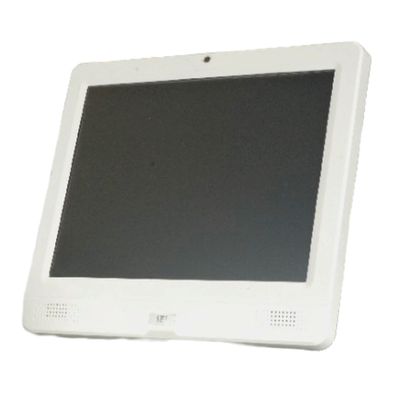
IEI Technology AFOLUX AFL-315AW/B Manuals
Manuals and User Guides for IEI Technology AFOLUX AFL-315AW/B. We have
1
IEI Technology AFOLUX AFL-315AW/B manual available for free PDF download: User Manual
IEI Technology AFOLUX AFL-315AW/B User Manual (198 pages)
Brand:
IEI Technology
| Category:
Desktop
| Size: 11.4 MB
Table of Contents
Table of Contents
7
Manual Conventions
4
1 Introduction
17
Afolux Afl-315Ab/W Series Flat Panel Pc Overview
18
Figure 1-1: AFOLUX AFL-315AW
18
Features and Model Variations
19
Applications
19
Standard Features
19
External Overview
20
Front Panel
20
General Description
20
Rear Panel
21
Figure 1-2: AFL-315 Front View
21
Figure 1-3: AFL-315 Rear View
22
I/O Interface Panel
22
Figure 1-4: AFL-315 I/O Interface Connector Panel
23
Figure 1-5: AFL-315 Top View
23
Figure 1-6: AFL-315 Bottom View
23
Top Panel and Bottom Panel
23
Figure 1-7: AFL-315 Side Views
24
Internal Overview
24
Rear Panel Connectors
24
Specifications
25
Preinstalled Hardware Components
25
System Specifications
25
Table 1-1: AFL-315 Series System Specifications
27
2 Detailed Specifications
29
Dimensions
30
Front Panel Dimensions
30
Side Dimensions
30
Figure 2-1: AFL-315 Front Panel Dimensions (MM)
30
Figure 2-2: AFL-315 Side Panel Dimensions
31
Figure 2-3: AFL-315 Top and Bottom Panel Dimensions (MM)
31
Top and Bottom Panel Dimensions
31
Figure 2-4: Processor
32
Intel® Desk-Top Processor Support
32
Motherboard Components
33
Additional Memory
33
Installed Memory
33
Memory Support
33
Storage Capacity
34
Figure 2-5: Memory Module and Memory Socket
33
External Peripheral Interface Connectors
34
Serial Port Connectors
34
Figure 2-6: COM Ports and LED Indicators
34
Figure 2-7: RJ-45 Ethernet Connector
35
LAN Connectivity
35
External USB Connectors
36
Figure 2-8: External USB Ports
36
Keyboard and Mouse Connectivity
36
Afolux Afl-315 Front Side
37
Monitor
37
Figure 2-9: Keyboard and Mouse Connector
37
Graphics
38
Intel ® 945G Integrated Graphics Media Accelerator 950
38
Figure 2-10: XGA Screen
38
Touch-Screen Module
38
DVI Graphics
39
Figure 2-11: VGA Connector
39
Figure 2-12: DVI Connector
39
Audio
40
Audio Codec '97 Controller
40
Stereo Speakers
40
Figure 2-13: Audio Codec and Audio Jacks
40
Dual-Display
40
System Power
41
AT Power Mode
41
Power Mode
41
Power Connectors
42
Power Supply
42
Figure 2-14: Stereo Speakers
41
ATX Power Mode
42
Wireless Connections
44
USB Bluetooth Module
44
Figure 2-15: Power Supply Unit
42
Power Input Connector
43
Power Output Connector
43
Connector for Cash Draw Power
43
Figure 2-16: Power Connectors
43
Figure 2-17: RJ-12 Connector
44
Figure 2-18: Bluetooth Module
45
Wireless Ethernet
45
Figure 2-19: PIFA Antenna
46
Optional Modules
46
GPRS Module (Optional)
46
System Ventilation
46
Figure 2-20: Internal View of Cooling Fans
47
Figure 2-21: Cooling Fan Dimensions
47
3 Unpacking
49
Unpacking
50
Packing List
50
4 Installation
53
Anti-Static Precautions
54
Installation Precautions
54
Preinstalled Components
55
Installation and Configuration Steps
55
Removing the Back Panel
56
Figure 4-1: Rear Panel Retention Screws
56
Cf Card Installation
57
Figure 4-2: HDD Bracket Retention Screws
57
Jumper Settings
58
Figure 4-3: CF Card Insert
58
Figure 4-4: Jumper Locations
58
Access the Jumpers
59
Preconfigured Jumpers
59
Table 4-1: Jumpers
59
Clear CMOS Jumper
60
Table 4-2: Preconfigured Jumpers
60
COM1 to COM6 Pin 9 Select
61
Table 4-3: Clear CMOS Jumper Settings
61
COM6 RX Function Select Jumper
62
Figure 4-5: Clear CMOS Jumper
61
Table 4-4: COM1, COM4, COM5 and COM6 Pin 9 Setting Jumper Settings
62
COM6 TX Function Select Jumper
63
Figure 4-6: COM1, COM4, COM5 and COM6 Pin 9 Setting Jumper Location
62
Table 4-5: COM6 RX Function Select Jumper Settings
63
Figure 4-7: COM6 RX Function Select Jumper Location
63
Table 4-6: COM6 TX Function Select Jumper Settings
64
COM6 RS-232/422/485 Serial Port Select Jumper
65
Figure 4-8: COM6 TX Function Select Jumper Pinout Locations
64
Table 4-7: COM6 RS-232/422/485 Serial Port Select Jumper Settings
65
At/Atx Mode Selection
66
Figure 4-9: COM6 RS-232/422/485 Serial Port Select Jumper Location
66
Figure 4-10: Back Cover Retention Screws
67
Mounting the System
68
Figure 4-11: AT/ATX Switch
68
Wall Mounting
69
Figure 4-12: Wall-Mounting Bracket
69
Figure 4-13: Chassis Support Screws
70
Panel Mounting
71
Figure 4-14: Secure the Panel PC
71
Figure 4-15: AFL-315 Panel Opening
72
Figure 4-16: Tighten the Panel Mounting Clamp Screws
72
Arm Mounting
73
Cabinet and Rack Installation
74
Figure 4-17: AFL-315 Arm Mounting Retention Screw Holes
74
Figure 4-18: the Rack/Cabinet Bracket
75
Figure 4-19: Secure the Rack/Cabinet Bracket
75
Bottom Panel Connectors
76
LAN Connection
76
Figure 4-20: Install into a Rack/Cabinet
76
Figure 4-21: LAN Connection
77
Serial Device Connection
77
Figure 4-22: Serial Device Connector
78
Figure 4-23: USB Device Connection
79
USB Device Connection
79
Figure 4-24: Preparing for Driver Installation
80
Webcam Driver Installation
80
Figure 4-25: Driver Installation Starting Screen
81
Figure 4-26: Ready to Install Driver
82
Figure 4-27: Driver Installs
83
Figure 4-28: Confirm Digital Signature
84
Figure 4-29: Installation Complete
85
Figure 4-30: Restart the Computer
86
5 System Maintenance
87
System Maintenance Introduction
88
Anti-Static Precautions
88
Turn off the Power
89
Opening the System
89
Removing the Back Panel
89
Figure 5-1: Rear Panel Retention Screws (Back)
90
Figure 5-2: Rear Panel Retention Screws (Bottom)
90
Figure 5-3: Back Cover Retention Screws
91
Removing the Metal Cover
91
Removing the Plastic Cover
91
Figure 5-4: Metal Enclosure Retention Screws
92
Figure 5-5: Peripheral Interface Connector Screwdrivers
93
Figure 5-6: Peripheral Connector Retention Screws
93
Figure 5-7: Processor and DIMM Housing
94
Removing the Processor and DIMM Housing
94
Replacing Components
95
Hard Disk Drive Replacement
95
Figure 5-8: HDD Bracket Retention Screws
95
CF Card Replacement
96
Figure 5-9: HDD Retention Screws
96
Figure 5-10: Locate the CF Card
97
DIMM Module Replacement
98
Figure 5-11: DIMM Socket Location
99
CPU Replacement
100
Figure 5-12: Installing a DIMM
100
Figure 5-13: Heat Sink Retention Screws
101
Figure 5-14: Processor
102
Figure 5-15: Open the CPU Socket Load Plate
102
Figure 5-16: Insert the Socket LGA775 CPU
103
Cooling Fan Replacement
104
Figure 5-17: Fan Retention Screws
105
Figure 5-18: Fan Cable Connectors
105
Reinstalling the Covers
106
6 Ami Bios Setup
107
Introduction
108
Starting Setup
108
Using Setup
108
BIOS Menu Bar
109
Getting Help
109
Unable to Reboot after Configuration Changes
109
Table 6-1: BIOS Navigation Keys
109
Main
110
System Overview
110
Advanced
111
System Date [XX/XX/XX]
111
CPU Configuration
112
IDE Configuration
114
System Time [XX:XX:XX]
111
ATA/IDE Configurations [Compatible]
114
Configure SATA as [IDE]
115
Configure SATA Channels [Behind PATA]
115
IDE Master and IDE Slave
115
IDE Master, IDE Slave
116
Auto-Detected Drive Parameters
116
Type [Auto]
117
Block (Multi Sector Transfer) [Auto]
118
Lba/Large Mode [Auto]
118
Zip
118
DMA Mode [Auto]
119
PIO Mode [Auto]
119
Auto]
120
Super IO Configuration
121
32Bit Data Transfer [Enabled]
121
Digital I/O Address [2D8H]
122
Serial Port1 Address [3F8/IRQ4]
123
Serial Port1 Mode [Normal]
123
Serial Port2 Address [2F8/IRQ3]
123
Parallel Port Address [Disabled]
124
Parallel Port Mode [Normal]
124
Serial Port2 Mode [Normal]
124
Parallel Port IRQ [IRQ7]
125
Serial Port3 Address [3E8]
125
Select RS232 or RS485/RS422 [RS/232]
126
Serial Port4 Address [2E8]
126
Serial Port5 Address [2E0]
126
Serial Port6 Address [2D8]
126
Hardware Health Configuration
127
FAN N Mode Setting [Full on Mode]
128
Temp. Limit of off [000]
129
Temp. Limit of Full [080]
130
Temp. Limit of Start [020]
130
Fan Start PWM [070]
131
Slope PWM [1 PWM]
131
CPU Fan PWM Control [070]
132
Monitored Parameters
132
ACPI Configuration
133
Power Configuration
133
AT/ATX Power [ATX Power]
133
Suspend Mode [S1(POS)]
134
APM Configuration
135
Power Button Mode [On/Off]
135
Restore on AC Power Loss [Power Off]
136
Resume on Keyboard/Mouse [Disabled]
136
Resume on PCIE [Enabled]
136
Remote Access Configuration
137
Resume on Ring [Disabled]
136
Resume on RTC Alarm [Disabled]
137
RTC Alarm Date (Days)
137
System Time
137
Remote Access [Disabled]
138
Serial Port Mode
138
Serial Port Number
138
Base Address, IRQ [3F8H,4]
139
Flow Control
139
Redirection after BIOS POST
139
Serial Port Mode [115200 8,N,1]
139
Serial Port Number [COM1]
139
Sredir Memory Display Delay
139
Terminal Type
139
VT-UTF8 Combo Key Support
139
Flow Control [None]
140
Redirection after BIOS POST [Always]
140
Terminal Type [ANSI]
140
USB Configuration
141
Sredir Memory Display Delay [Disabled]
141
VT-UTF8 Combo Key Support [Disabled]
141
USB Function [Enabled]
142
Legacy USB Support [Enabled]
143
Pci/Pnp
143
USB 2.0 Controller [Enabled]
143
USB2.0 Controller Mode [Hispeed]
143
IRQ# [Available]
144
DMA Channel# [Available]
145
Boot
146
Boot Settings Configuration
146
Quick Boot [Enabled]
147
Quiet Boot [Disabled]
147
Addon ROM Display Mode [Force BIOS]
148
Boot from LAN Support [Disabled]
148
Boot Device Priority
149
Bootup Num-Lock [Off]
148
Change Supervisor Password
150
Security
150
Change User Password
151
Northbridge Chipset Configuration
152
Chipset
151
Boot Display Device [CRT + LFP]
153
Memory Hole [Disabled]
153
Flat Panel Type [By Jumper]
154
Internal Graphics Mode Select [Enable, 8MB]
154
Southbridge Configuration
155
Audio Controller [AC'97 Audio Only]
156
Cashdraw Controller [Enabled]
156
Exit
156
Spectrum [Disabled]
156
Discard Changes
157
Discard Changes and Exit
157
Save Changes and Exit
157
Load Failsafe Defaults
158
Load Optimal Defaults
158
7 System Monitoring
159
IEI Intelligent System Management Module (Ismm)
160
Ismm Features
160
What Is Ismm
160
Figure 7-1: Ismm
160
Com Port Led Indicators
161
Asystem Specifications
163
Motherboard Specifications
164
Processor Specifications
165
Screen Specifications
165
Touch Screen Specifications
166
Power Supply Module
167
Webcam Specifications
168
Bluetooth Module Specifications
168
Cooling Fan Specifications
169
Optional Gprs Module Specifications
169
Table 7-1: Bluetooth Module Specifications
169
External Connector Pinouts
171
Introduction
172
DVI Connector
172
Keyboard/Mouse Connector
172
Lan Connectors
173
Cash Drawer Connector
173
Serial Port Connectors
174
Usb Connector
174
Vga Connector
174
Csafety Precautions
177
Safety Precautions
178
General Safety Precautions
178
Anti-Static Precautions
179
Maintenance and Cleaning Precautions
179
Maintenance and Cleaning
179
Cleaning Tools
180
Dbios Configuration Options
183
Bios Configuration Options
183
D.1 BIOS Configuration Options
184
Ewatchdog Timer
187
Example Program
189
Fhazardous Materials Disclosure
191
Hazardous Material Disclosure Table for IPB Products Certified as Rohs Compliant under 2002/95/EC Without Mercury
192
Index
195
Advertisement
Advertisement
Related Products
IEI Technology AFL3-12A/W15A-BT
IEI Technology AFL3-12A-BT
IEI Technology AFL3-W15A-BT
IEI Technology AFL3-08A-BT
IEi Technology AFL2-12A-HM65 Series
IEI Technology AFL-W19A
IEI Technology AFL-W19B
IEI Technology AFL-42A-9652
IEI Technology AFL2-W15A-N270/L325
IEI Technology AFL-xxA-N26
IEI Technology Categories
Motherboard
Touch Panel
Computer Hardware
Single board computers
Desktop
More IEI Technology Manuals
Login
Sign In
OR
Sign in with Facebook
Sign in with Google
Upload manual
Upload from disk
Upload from URL