Sign In
Upload
Manuals
Brands
IEI Technology Manuals
Touch Panel
PPC-5152-D525-E
IEI Technology PPC-5152-D525-E Manuals
Manuals and User Guides for IEI Technology PPC-5152-D525-E. We have
1
IEI Technology PPC-5152-D525-E manual available for free PDF download: User Manual
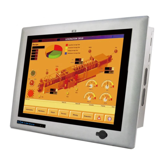
IEI Technology PPC-5152-D525-E User Manual (132 pages)
15" with Touchscreen, Intel Atom CPU, USB 3.0, Dual Gigabit Lan, RS-232/422/485, IP 64 Protection, RoHS Compliant
Brand:
IEI Technology
| Category:
Touch Panel
| Size: 5 MB
Table of Contents
Table of Contents
5
1 Introduction
13
Overview
14
Figure 1-1: PPC-5152-D525-E Panel PC
14
Features
15
External Overview
16
Bottom Panel
16
Figure 1-2: Front View
16
Front Panel
16
Figure 1-3: Bottom View
17
Figure 1-4: Side View
18
Figure 1-5: Top View
18
Side Panels
18
Top Panel
18
Figure 1-6: Rear View
19
Rear Panel
19
Backplane Options
20
Figure 1-7: Backplane Option (HPE-2S2)
20
Dimensions
21
Figure 1-8: PPC-5152-D525-E Dimensions (MM)
21
Specifications
22
Table 1-1: System Specifications
24
Power Adapter Specifications
25
Table 1-2: Power Adapter Specifications
25
2 Unpacking
26
Unpacking
27
Packing List
28
3 Installation
30
Anti-Static Precautions
31
Installation Precautions
31
Preinstalled Components
32
Compactflash® Installation
32
Figure 3-1: Compactflash® Cover Screws
32
Hdd Installation
33
Figure 3-2: Compactflash® Slot
33
Figure 3-3: Rear Panel Retention Screws
33
Figure 3-4: HDD Bracket Retention Screws
34
Figure 3-5: HDD Installation
34
Figure 3-6: HDD Bracket Installation
35
Pci Expansion Card Installation
36
Figure 3-7: PCI Expansion Slot Retention Screw
37
Figure 3-8: Install PCI Card
37
Pcie Expansion Card Installation (Optional)
38
Figure 3-9: Pice Expansion Slot Retention Screw
39
Figure 3-10: Install Pcie Card
39
Mounting the System
40
Arm Mounting
40
Figure 3-11: VESA Compliant Arm
40
Figure 3-12: Arm Mounting Retention Screw Holes
41
Figure 3-13: Suggested Panel Cut out Size for PPC-5152-D525-E (Unit: MM)
42
Panel Mounting
42
Figure 3-14: Panel Mounting Clamp Slots (Side View)
43
Figure 3-15: Tighten the Panel Mounting Clamp Screws
44
Rack/Cabinet Mounting
44
Figure 3-16: the Rack/Cabinet Bracket
45
Figure 3-17: Secure the Rack/Cabinet Bracket
45
Figure 3-18: Install into a Rack/Cabinet
46
Figure 3-19: VESA Compliant Stand
46
Stand Mounting
46
Figure 3-20: Stand Mounting Retention Screw Holes
47
Wall Mounting
47
Figure 3-21: Wall-Mounting Bracket
48
Figure 3-22: Chassis Support Screws
49
Bottom Panel Connectors
50
Figure 3-23: Secure the Panel PC
50
LAN Connector
50
Table 3-1: LAN Pinouts
50
Figure 3-24: RJ-45 Ethernet Connector
51
Power Input, DIN Connector
51
Serial Port (COM1, COM2)
51
Table 3-2: RJ-45 Ethernet Connector Leds
51
Figure 3-25: RS-232 Serial Port
52
RS-232/422/485 Serial Port (COM3)
52
Table 3-3: RS-232 Serial Port Pinouts
52
COM3 Mode Select Switch
53
Figure 3-26: RS-232/422/485 Serial Port
53
Table 3-4: RS-232/422/485 Serial Port Pinouts
53
Figure 3-27: COM3 RS-232/422/485 Serial Port Select Switch Location
54
RS-422/485 Serial Port (COM4, COM5)
54
Table 3-5: COM3 RS-232/422/485 Serial Port Select Settings
54
Figure 3-28: RJ-45 RS-422/485 Serial Port
55
Table 3-6: RJ-45 RS-422/485 Serial Port Pinouts
55
Figure 3-29: RJ-45 RS-422/485 Serial Device Connection
56
Figure 3-30: RS-422/485 Serial Port (DB-9)
56
Table 3-7: RS-422/485 Serial Port Pinouts
57
Table 3-8: USB 2.0 Port Pinouts
57
USB 2.0 Connectors
57
USB 3.0 Connectors
57
Figure 3-31: VGA Connector
58
Table 3-9: USB 3.0 Port Pinouts
58
VGA Connector
58
Power-Up the System
59
AT/ATX Power Mode Selection
59
Figure 3-32: AT/ATX Power Mode Switch
59
Table 3-10: VGA Connector Pinouts
59
Figure 3-33: Power Button
60
Powering On/Off in ATX Power Mode
60
4 System Maintenance
61
System Maintenance Introduction
62
Anti-Static Precautions
62
Turn off the Power
63
Opening the System
63
Memory Module Replacement
64
Figure 4-1: Back Cover Retention Screws
64
Figure 4-2: DDR SO-DIMM Module Installation
65
5 Ami Bios Setup
66
Introduction
67
Starting Setup
67
Using Setup
67
BIOS Menu Bar
68
Getting Help
68
Table 5-1: BIOS Navigation Keys
68
Main
69
BIOS Information
69
System Date [XX/XX/XX]
69
Advanced
70
System Time [XX:XX:XX]
70
ACPI Settings
71
ACPI Sleep State [S1 (CPU Stop Clock)]
71
RTC Wake Settings
72
Wake System with Fixed Time [Disabled]
72
CPU Configuration
73
Hyper Threading Function [Enabled]
74
IDE Configuration
75
ATA or IDE Configurations [Enhanced]
75
Configure SATA as [IDE]
75
USB Configuration
76
USB Devices
76
Super IO Configuration
77
Legacy USB Support [Enabled]
77
Serial Port [Enabled]
77
Serial Port N Configuration
78
Change Settings [Auto]
78
Serial Port 1 Mode [RS232]
79
Serial Port [Enabled]
80
Change Settings [Auto]
80
Serial Port 2 Mode [RS232]
80
Serial Port 3 Mode [RS232]
80
Change Settings [Auto]
81
Serial Port 4 Mode [RS422/485]
81
Serial Port [Enabled]
81
Serial Port 5 Mode [RS422/485]
82
H/W Monitor
83
PC Health Status
83
Console Redirection Settings
84
Serial Port Console Redirection
84
Console Redirection [Disabled]
84
Terminal Type [ANSI]
85
Bits Per Second [115200]
85
IEI Feature
86
Auto Recovery Function [Disabled]
86
Chipset
87
Host Bridge Configuration
88
Initiate Graphics Adapter [IGD]
88
Onchip VGA Configuration
89
IGD Memory [8 MB]
89
South Bridge Configuration
90
Restore on AC Power Loss [Last State]
90
High Definition Audio Controller [Enabled]
90
Set Spread Spectrum Function [Disabled]
90
WIFI Support [Enabled]
90
Auto Dimming Support [Disabled]
90
Intel IGD SWSCI Opregion
92
Power Saving Function [Disabled]
92
DVMT Mode Select [DVMT Mode]
92
Boot
93
DVMT/FIXED Memory [Maximum]
93
IGD - Boot Type [VBIOS Default]
93
Bootup Numlock State [On]
94
Quiet Boot [Enabled]
94
Launch PXE Oprom [Disabled]
94
Security
95
UEFI Boot [Disabled]
95
Administrator Password
95
User Password
95
Save & Exit
96
Save Changes and Reset
96
Discard Changes and Reset
96
Restore Defaults
96
Save as User Defaults
96
Restore User Defaults
96
6 Software Drivers
98
Available Software Drivers
99
Starting the Driver Program
99
Chipset Driver Installation
99
Figure 6-1: Chipset Driver Screen
100
Figure 6-2: Chipset Driver Welcome Screen
100
Figure 6-3: Chipset Driver License Agreement
101
Figure 6-4: Chipset Driver Read Me File
102
Figure 6-5: Chipset Driver Setup Operations
102
Graphics Driver Installation
103
Figure 6-6: Chipset Driver Installation Finish Screen
103
Figure 6-7: Graphics Driver Read Me File
104
Figure 6-8: Graphics Driver Setup Files Extracted
104
Figure 6-9: Graphics Driver Welcome Screen
105
Figure 6-10: Graphics Driver License Agreement
105
Figure 6-11: Graphics Driver Read Me File
106
Figure 6-12: Graphics Driver Setup Operations
106
Lan Driver Installation
107
Figure 6-13: Graphics Driver Installation Finish Screen
107
Figure 6-14: LAN Driver Welcome Screen
108
Figure 6-15: LAN Driver Welcome Screen
108
Figure 6-16: LAN Driver Installation
109
Figure 6-17: LAN Driver Installation Complete
109
Touchscreen Driver Installation
110
Figure 6-18: Touchscreen Driver Welcome Screen
110
Figure 6-19: Touchscreen Driver License Agreement
111
Figure 6-20: Touchscreen Driver Choose Install Location
111
Figure 6-21: Touchscreen Driver Installation Screen
112
Figure 6-22: Touchscreen Driver Update Complete
112
Calibrating the Touchscreen
113
Figure 6-23: Penmount Monitor Icon
113
Figure 6-24: Penmount Monitor Popup Menu
113
Figure 6-25: Configuration Screen
114
Figure 6-26: Calibration Initiation Screen
114
Usb 3.0 Driver Installation
115
Figure 6-27: Calibration Screen
115
Figure 6-28: USB 3.0 Driver Welcome Screen
116
Figure 6-29: USB 3.0 Driver License Agreement
116
Figure 6-30: USB 3.0 Driver Installation Screen
117
Figure 6-31: USB 3.0 Driver Update Complete
117
A Bios Configuration Options
118
A.1 BIOS Configuration Options
119
A.1 Bios C Onfiguration O Ptions
119
Bios Configuration Options
119
B Safety Precautions
121
Safety Precautions
122
General Safety Precautions
122
Anti-Static Precautions
123
Product Disposal
123
Maintenance and Cleaning Precautions
124
B.2 M Aintenance and C Leaning P Recautions
124
Maintenance and Cleaning
124
Cleaning Tools
125
C Watchdog Timer
126
Example Program
128
D Hazardous Materials Disclosure
129
Hazardous Material Disclosure Table for IPB Products Certified as Rohs Compliant under 2002/95/EC Without Mercury
130
Advertisement
Advertisement
Related Products
IEI Technology PPC-5152-D525
IEI Technology PPC-5150A-G41
IEI Technology PPC-5170A-G41
IEI Technology PPC-5190A-G41
IEI Technology PPC-5050A
IEI Technology PPC-5020
IEI Technology PPC-F08B
IEI Technology PPC-FW19C-Q370-P/PC/25
IEI Technology PPC-FW19C-Q370-i7/PC/25
IEI Technology PPC2-CW156-ADLP-i5/8G
IEI Technology Categories
Motherboard
Touch Panel
Computer Hardware
Single board computers
Desktop
More IEI Technology Manuals
Login
Sign In
OR
Sign in with Facebook
Sign in with Google
Upload manual
Upload from disk
Upload from URL