
Related Manuals for Planet ICS-100


Summary of Contents for Planet ICS-100
- Page 1 User’s Manual ICS-100 / ICS-101 / ICS-102 / ICS-102S15 RS-232/RS-422/RS-485 over 100Base-FX / 10/100Base-TX Media Converter...
- Page 2 PLANET has made every effort to ensure that this User's Manual is accurate; PLANET disclaims liability for any inaccuracies or omissions that may have occurred.
- Page 3 User’s Manual of ICS-10x Revision PLANET RS-232/RS-422/RS-485 over 10/100Base-TX/100Base-FX Media Converter User's Manual FOR MODELS: ICS-100 / ICS-101 / ICS-102 / ICS-102S15 REVISION: 1.4 (JANUARY.2011) Part No.: 2080-AA3600-004...
-
Page 4: Table Of Contents
User’s Manual of ICS-10x TABLE OF CONTENTS 1. INTRODUCTION ......................1 1.1 P ..........................1 ACKAGE ONTENTS 1.2 H ......................... 1 OW TO ANUAL 1.3 P ..........................2 RODUCT ESCRIPTION 1.4 A ............................2 PPLICATIONS 1.5 P ..........................4 RODUCT EATURES 1.6 PRODUCT SPECIFICATION ........................ - Page 5 VCOM U ........................ 55 NSTALLING THE TILITY 5.2 S ..........................58 EARCH THE EVICE 5.3 V COM............................59 IRTUAL APPENDIX A........................62 A.1 PLANET S ....................... 62 MART ISCOVERY TILITY A.2 D ‘ RS-232/RS-422/RS-485 P ................63 EVICE SSIGNMENTS A.3 D ‘...
-
Page 6: Introduction
User’s Manual of ICS-10x 1. INTRODUCTION Thank you for purchasing PLANET Serial over Fast Ethernet Media Converter – ICS-10x series. Terms of “Serial Media Converter” means the products mentioned titled in the cover page of this User’s manual 1.1 Package Contents Open the box of the Serial Media Converter and carefully unpack it. -
Page 7: Product Description
Ethernet signal that allows two types of segments to connect easily, efficiently and inexpensively. This converter can be used as a stand-alone unit or as a slide-in module to the PLANET Media Converter Chassis (MC-700, MC-1500 and MC-1500R). It’s time saving expense for user and SI, no need to replace the existing Serial equipment and software system. - Page 8 User’s Manual of ICS-10x Process Control To monitor, configure and manage the Robot conveyer including other machines in a manufacturing, PLC (Programmable Logical Control) is required. The PLC is used to drive above the manufacturing machines process. The ICS-10x can be set to TCP Server mode and connect the PLC.
-
Page 9: Product Features
Built-in IP-Base Web interface for remote management Serial Operation mode selected via Web management Pair Connection mode for connecting two serial devices over a network PLANET Smart Discovery utility automatically finds xxx devices on the network Firmware upgrade via HTTP protocol Hardware... -
Page 10: Product Specification
System: Power TP or Fiber Port: Link / Active LED Indicators Serial Port: Link / Active Web Management PLANET VCOM Utility Management PLANET Smart Discovery Utility TCP Server TCP Client UDP Client Virtual COM Operation Mode Telnet Server Pair Connection – Remote (Slave) Pair Connection –... - Page 11 User’s Manual of ICS-10x External Power Adaptor 5V DC / 2A max. Power Supply 5.5 Watts (maximum) Power Consumption Metal Mechanical Operating Temperature: 0~50 Degree C Storage Temperature: -10~70 Degree C Environment Humidity: 10%~90% RH (operating) 5%~90% RH (Storage) FCC Class A, CE Certification Class A Emissions IEEE 802.3 Ethernet, 10Base-T IEEE 802.3u Fast Ethernet, 100Base-TX / 100Base-FX...
-
Page 12: Installation
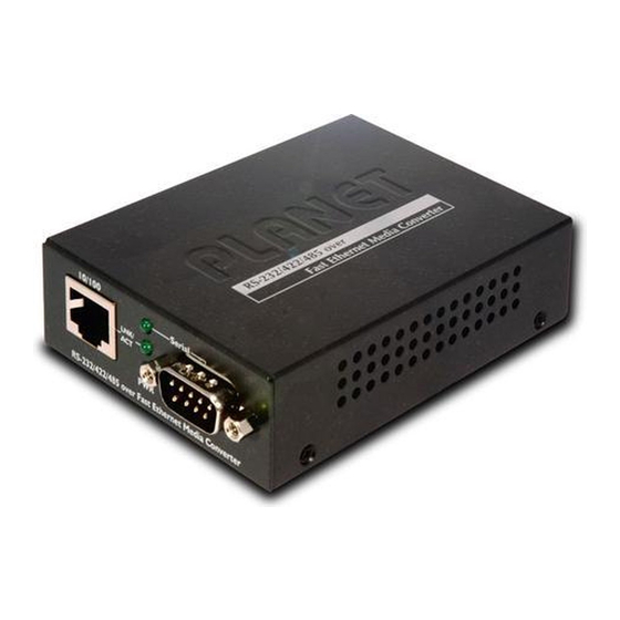
LED indicators. Before connecting any network device to the Serial Media Converter, please read this chapter completely. 2.1 Hardware Description 2.1.1 Product Layout Figure 2-1 to Figure 2-4 show layout and front panel of ICS-10x. ICS-100 – RS-232 / RS-422 / RS-485 over 10/100Base-TX Figure 2-1 ICS-100 panel layout... - Page 13 User’s Manual of ICS-10x Figure 2-2 PLANET ICS-100 Front Panel ICS-101 – RS-232 / RS-422 / RS-485 over 10/100Base-FX Figure 2-3 ICS-101 panel layout...
- Page 14 User’s Manual of ICS-10x Figure 2-4 PLANET ICS-101 Front Panel ICS-102 / ICS-102S15 – RS-232 / RS-422 / RS-485 over 10/100Base-FX Figure 2-5 ICS-102 / ICS-102S15 panel layout...
-
Page 15: Led Indicators
User’s Manual of ICS-10x Figure 2-6 PLANET ICS-102 Front Panel 2.1.2 LED Indicators Color Function Lights to ind icate that Converter is powe red on. Green indicate that the Fast Ethernet Port s succes sfully connectin g to the Lights... -
Page 16: Ics-10X Rear Panel
Please read the following topics and perform the procedures in the order being presented. The hard ware installation of PLANET ICS-10x Web Smart Media Converter do not need software configuration. To install your ICS -10x on a desktop or shelf, simply complete the following steps. - Page 17 User’s Manual of ICS-10x Step 6: Turn on the power of the device/station; the PWR LED (Green) should light when all cables are attached. Figure 2-6 ICS-100 stand alone installation Figure 2-7 ICS-101 / ICS-102 / ICS-102S15 stand alone installation Please refers to APPENDIX-A for detailed wiring information of the ICS-10x.
-
Page 18: Chassis Installation And Rack Mounting
User’s Manual of ICS-10x 2.2.2 Chassis Installation and Rack Mounting To install the Media Converter in a 10-inch or 19-inch with standard rack, follow the instructions described below. Step 1: Place your ICS-10x on a hard flat surface, with the front panel positioned towards your front side. Step 2: Carefully slide in the module until it is fully and firmly fitted into the slot of the chassis. -
Page 19: Management
Please refer to the following Chapter 4 for more details. 3.2 Requirements ■ Network cables. For ICS-100: Use standard network (UTP) cables with RJ-45 connectors. For ICS-101: Use Multi-mode fiber patch cord with ST connectors. For ICS-102 / ICS-102S15: Use Multi-mode or Single-mode fiber patch cord with SC connectors. -
Page 20: Management Methods
- Web Management via a network or dial-up connection 3.3.1 Web Management The PLANET Web-Smart Media Converter provides a built-in browser interface. You can manage the ICS-10x remotely by having a remote host with web browser, such as Microsoft Internet Explorer, Netscape Navigator or Mozilla Firefox. - Page 21 User’s Manual of ICS-10x Figure 3-2 Login screen For security reason, please change and memorize the new password after this first setup. Only accept command in lowercase letter under web interface. -16-...
-
Page 22: Web Configuration
User’s Manual of ICS-10x 4. WEB CONFIGURATION The ICS-10X Web Smart Media Converter provide Web interface for Converter smart function configuration and make the Converter operate more effectively - They can be configured through the Web Browser. A network administrator can manage and monitor the ICS-10x from the local LAN. -
Page 23: System
User’s Manual of ICS-10x 4.2 System 4.2.1 System Information The System Information page provides information for the current device. System Info page helps a network manager to identify the versions and IP Address etc. The screen in Figure 4-2 appears. Figure 4-2 System Information screen The page includes the following fields: •... -
Page 24: Password Setting
User’s Manual of ICS-10x 4.2.2 Password Setting This function provides administrator to secure Web login. The screen in Figure 4-3 appears. Figure 4-3 Password Setting screen The page includes the following configurable data: • Login Name Displays the user name. •... -
Page 25: Firmware Upgrade
User’s Manual of ICS-10x 4.2.3 Firmware Upgrade The Firmware Upgrade page contains fields for downloading system image files from the Local File browser to the device. The screen in Figure 4-4 appears. Figure 4-4 Firmware Upgrade screen To open Firmware Upgrade screen perform the folling: Click System ->... - Page 26 User’s Manual of ICS-10x Then the “Firmware Upgrade Mode” displayed as in Figure 4-6. Figure 4-6 Firmware Upgrade screen Click the “Browse” button of the main page, the system would pop up the file selection menu to choose firmware. Figure 4-7 Windows file selection menu popup Select on the firmware then click “Upgrade”.
-
Page 27: Factory Default
User’s Manual of ICS-10x 4.2.4 Factory Default The Factory Default can reset the ICS-10x back to the factory default mode. Be aware that the entire configuration will be reset, and the IP address of the ICS-10x will be set to “192.168.0.100”. The screen in Figure 4-8 appears. Figure 4-8 Factory Default progress screen 4.2.5 System Reboot The System Reboot can restart the ICS-10x. -
Page 28: Network Configuration
• DNS DNS is the way that Internet domain names are identified and translated into IP addresses. A domain name is an alphanumeric name, such as planet.com, that it is usually easier to remember. Assign the DNS server IP address. -
Page 29: Operation Mode
When DHCP Client is set to Enable, the IP Address, Subnet Mask, Gateway and DNS fields are not allow to be changed. If the ICS-10x is set to DHCP Client enable, you can use PLANET Smart Discovery or PLANET VCOM Utility to search the ICS-10x which with DHCP assigned IP address. -
Page 30: Tcp Server Mode
User’s Manual of ICS-10x 4.4.1 TCP Server Mode When the ICS-10x be configured to TCP Server mode, it allows Serial device that connected to serial port of ICS-10x to establish TCP communication over Intranet or Internet network between: Remote Host (Computer) with Serial applications using TCP/IP network socket programs Other ICS-10x with TCP Client mode It opens the TCP port of ICS-10x to wait for serial application to establish a TCP connection. - Page 31 User’s Manual of ICS-10x Pair Connection - Remote(Slave) The default mode is “Disable”. • TCP Port Number The TCP port that ICS-10x uses to listen to connections and that other device must use to contact ICS-10x. To avoid conflicts with well known TCP ports, the default is set to “1024”.
- Page 32 User’s Manual of ICS-10x Mode: RS-232 Baudrare: 9600 Character Bits: Parity Type : none Stop Bit : Hardware Flow Control: Figure 4-15 Example: Serial Port Configuration screen Hyper Terminal setup a new connection with TCP/IP Winsock Open HyperTerminal Figure 4-16 Example: Hyper Terminal screen -27-...
- Page 33 User’s Manual of ICS-10x On the File menu, click New Connection. In the Name box, type a name that describe s the connection. In the Icon box, click the appropriate icon, and then click OK. Figure 4-17 Example: Hyper Terminal – Create new connectio In the Connect To dialog box, choose which port or modem you want to use in the Connect using drop-down box.
- Page 34 User’s Manual of ICS-10x Figure 4-19 Example: Hyper Terminal configuration Value Description The address or name of the connection you want to create. This can be in standard Internet Host address dotted notation (for example, w.x.y.z) or can be the site's user-friendly name. The number of the port that you want the connection to use.
-
Page 35: Tcp Client Mode
User’s Manual of ICS-10x 4.4.2 TCP Client Mode When the ICS-10x be configured to TCP Client mode, it allows Serial device that connected to serial port of ICS-10x to establish TCP communication actively over Intranet or Internet network between: Remote Host (Computer) with Serial applications using TCP/IP network socket programs Other ICS-10x with TCP Server mode After the data has been transferred, the ICS-10x can disconnect automatically from the Remote Host depends on the TCP Inactive timeout settings. -
Page 36: Udp Client Mode
User’s Manual of ICS-10x 4.4.3 UDP Client Mode When the ICS-10x be configured to UDP Client mode, it allows Serial device that connected to serial port of ICS-10x to quickly transmit data to multiple Remote Hosts over Intranet or Internet network by unicast or multicast. It also makes the Serial device to receive data from more than one Remote Hosts. -
Page 37: Virtual Com Mode
User’s Manual of ICS-10x The page includes the following fields: • Local UDP Port Enter the local port number • Remote Address Enter the IP address of the remote device. • Remote Port Enter the remote port number of the remote device. 4.4.4 Virtual COM Mode When the ICS-10x be configured to Virtual COM mode, it allows Serial device that connected to serial port of ICS-10x to establish TCP communication over Intranet or Internet network between Remote Host (Computer). - Page 38 The unit drops the connection if there is no activity on the serial line before the set time expires. To disable the inactive timeout enter “0”. Example: Use PLANET VCOM Utility + Microsoft Windows Hyper terminal COM Port mode Figure 4-27 Virtual COM mode...
- Page 39 User’s Manual of ICS-10x From the WEB interface, set the Serial operation mode of ICS-10 x to “Virtual COM” and set the TCP Port Number to “1024”. Figure 4-28 Example: Virtual COM Configuration screen Set the Serial Port Configuration of ICS-10x as below: -34-...
- Page 40 User’s Manual of ICS-10x Mode: RS-232 Baudrare: 9600 Character Bits: Parity Type : none Stop Bit : Hardware Flow Control: Figure 4-29 Example: Serial Port Configuration screen -35-...
- Page 41 User’s Manual of ICS-10x VCOM Utility to create virtual COM port This mode will run with the software-“PLANET VCOM Utility”. Open the VCOM utility; click “Search” button to point out the ICS-10x that want to be configured. Figure 4-30 Example: Virtual COM Configuration screen...
- Page 42 User’s Manual of ICS-10x Figure 4-31 Example: Virtual COM Configuration screen Hyper Terminal setup a new connection with virtual COM port On the File menu, click New Connection. In the Name box, type a name that describes the connection. In the Icon box, click the appropriate icon, and then click OK. Figure 4-32 Example: HyperTerminal Configuration screen -37-...
- Page 43 User’s Manual of ICS-10x In the Connect to dialog box, choose which port you want to use in the Connect using drop-down box. In this case, choose COM9 (as created in Step-4) Figure 4-33 Example: HyperTerminal Configuration screen Set the parameter like below, click “Apply” to take effect. Figure 4-34 Example: HyperTerminal COM port properties screen -38-...
- Page 44 User’s Manual of ICS-10x After the Virtual COM connection is established, open the VCOM utility again to check the COM9 information. Figure 4-35 Example: VCOM Utility, COM9 information Then can use the console like connect the serial cable with the switch. Figure 4-36 Example: Hyper Terminal COM port screen -39-...
-
Page 45: Telnet Server Mode
User’s Manual of ICS-10x 4.4.5 Telnet Server Mode TELNET (TELecommunication NETwork) is a network protocol used on the Internet or local area network (LAN) connections. The Telnet protocol type is the correct setting for most servers and serial devices, such as Managed Ethernet switches or Gateways. - Page 46 User’s Manual of ICS-10x The ICS-10x’s “telnet server mode”--if the user used the MS-DOS telnet command it will show double character. So the user can use other Telnet software like: “putty” or “NetTerm”. Example 1: Telnet Command in Windows Platform Figure 4-39 Example Telnet Server Setup Operation Mode and Serial Port of ICS-10x Set the ICS-10x mode to “Telnet server mode”...
- Page 47 User’s Manual of ICS-10x Figure 4-40 Example Windows Excuse - Telnet While the Telnet window appears, type “open xxx,xxx,xxx,xxx”, xxx is the IP address of the ICS-10x Telnet Server. In this case we type “open 192.168.0.100” and press enter. Figure 4-41 Example Windows Excuse - Telnet Then can use the telnet connection to configure the switch just like console direct connect to the COM port of the switch.
- Page 48 User’s Manual of ICS-10x To quit the Telnet session, press “CTRL+]” and then type “quit” Figure 4-43 Example Windows Excuse - Telnet Example 2: Putty software in Windows Platform PuTTY is a free implementation of Telnet and SSH for Win32 and Unix platforms, along with an xterm terminal emulator. In this case we use Putty to telnet to the ICS-10x-Telnet Server mode for remote console login.
- Page 49 User’s Manual of ICS-10x Then can telnet IP address like to telnet switch’s IP. Figure 4-45 Putty telnet screen -44-...
-
Page 50: Pair Connection- Local Mode
User’s Manual of ICS-10x 4.4.6 Pair Connection– Local Mode The parameter defines the maintenance status for listen for the pair connection To make a long distance communication between two serial equipment, configure two ICS-10x with Pair Connection mode and setup one as a Master (Local side) and the other as a Slave (Remote side). -
Page 51: Pair Connection - Remote Mode
User’s Manual of ICS-10x 4.4.7 Pair Connection – Remote Mode The parameter defines the maintenance status for listen for the pair connection In effect, this converter will be acting as a TCP client. The screen in Figure 4-48 appears. When the changed operation mode, the user should be changed the Serial Port Configuration. Figure 4-48 Pair Connection –... - Page 52 User’s Manual of ICS-10x RS-232 cables! Example: Two ICS-10x with Pair Connection mode One be configured as Pair Connection – Local (Master) The other one be configured as Pair Connection – Remote (Slave) Via the RS-485 interface, the external scanners, speed dome cameras and PTZ receivers can be controlled by the keyboard which provides upward, downward, leftward, rightward, clockwise and counterclockwise with the joystick.
- Page 53 User’s Manual of ICS-10x Figure 4-49 Two ICS-10x configured with Pair-Connection Connect the converter with the IP camera for RS-485 interface like PLANET product: “ICA-601”. Connect the converter with the control keyboard for RS-485 interface like PLANET product: “CAM-KB300”. ICS-10x – Master: be configured as Pair-Connection-Local From Web interface, login the ICS-10x with IP address = 192.168.0.100, set up the operation mode of this unit to be...
- Page 54 User’s Manual of ICS-10x Figure 4-51 Pair Connection – Local, serial port configuration ICS-10x – Slave: be configured to Pair-Connection-Remote From Web interface, login the ICS-10x with IP address = 192.168.0.101, set up the operation mode of this unit to be “...
-
Page 55: Serial Port Configuration
User’s Manual of ICS-10x Then the control keyboard cans remote control the IP camera. 4.5 Serial Port Configuration The page shows the converter’s serial Port configuration. The screen in Figure 4-52 appears. Figure 4-52 Serial Port Configuration page screen The page include s the following fields: •... - Page 56 User’s Manual of ICS-10x the end of transmission. The default is “1”. • Hardware Flow Control Flow control manages data flow between devi ces in a network to ensure it is processed e fficiently. Too much data arriving before a device is prepared to manage it causes lost o r retransmitted data.
-
Page 57: Smtp
User’s Manual of ICS-10x 4.6 SMTP The page shows SMTP configuration. The screen in Figure 4-53 appears. You may setup SMTP mail parameters for further operation. That’s, if users want to send the alarm message out that contains “Log-Fail Warring”, “OP Change Warning”... - Page 58 User’s Manual of ICS-10x If authentication is required when an e-mail is sent • SMTP Login Information able Enter your login name for the SMTP Server. Username Enter your password for the SMTP Server. Password Enter the receiver’s e-mail address. •...
- Page 59 User’s Manual of ICS-10x Figure 4-55 Login screen -54-...
-
Page 60: Software Vcom Utility
If the welcome screen does not appear, click “Start” at the taskbar. Then, select “Run” and type NOTE: “D:\Software\PLANET VCOM Utility_v31\VCOMSETUP.exe”, assume “D” is your CD-ROM drive. Once the Setup program starts running, click Next when the Welcome window opens to proceed with the installation. - Page 61 User’s Manual of ICS-10x Click Install to install the program. Figure 5-2 VCOM installation screen The Installing window reports the progress of the installation. Click Finish to complete Figure 5-3 VCOM installation screen -56-...
- Page 62 User’s Manual of ICS-10x To run the PLANET VCOM utility on the computer, click “Start” \ “All Programs” \ “PLANET” \ “VCOM” \ “VCOM” Figure 5-4 VCOM program path -57-...
-
Page 63: Search The Device
User’s Manual of ICS-10x 5.2 Search the Device Click the Search button to find the ICS-10x. It will show the ICS-10x device name, project number, MAC address and IP address. Click the shortcut of VCOM on the desktop to run the VCOM program. Click "Search"... -
Page 64: Virtual Com
User’s Manual of ICS-10x 5.3 Virtual COM This function should be set the ICS-10x’s operation mode to “Virtual COM” on the Web. Choose to create port like below: If the device support Telnet, while user click “COM Mapping”. Figure 5-6 COM Mapping While user click “Add”... - Page 65 User’s Manual of ICS-10x Select device which user want and set up “TCP”,“Client” mode, “COM” number and “RemotePort” number. Click "OK" button to create new virtual com port and establish telenet connection Figure 5-8 Add Virtual COM Port Configuration Then set the HyperTerminal parameter Figure 5-9 Hyper Terminal Configuration -60-...
- Page 66 User’s Manual of ICS-10x then the VCOM will show connect information like below: Figure 5-10 VCOM Configuration Once the Virtual COM Port- COM9 connection is established, from the Windows Device Manager, a COM Port is added to the device list. Figure 5-11 Windows Device Server - Virtual COM Port When the Virtual COM create COM port, the Device Manager will add “Virtual Serial Port”.
-
Page 67: Planet Smart Discovery Utility
APPENDIX A A.1 PLANET Smart Discovery Utility For easily list the ICS-10x in your Ethernet environment, the Planet Smart Discovery Utility from user’s manual CD-ROM is an ideal solution. The following install instructions guiding you for run the Planet Smart Discovery Utility. -
Page 68: Device Srs-232/Rs-422/Rs-485 Pin Assignments
Switch under different IP subnet address. 6. Press “Connect to Device” button then the Web login screen appears. 7. Press “Exit” button to shutdown the planet Smart Discovery Utility. A.2 Device‘s RS-232/RS-422/RS-485 Pin Assignments DB9 Pin Define for RS-232 / RS-422 / RS-485... -
Page 69: Cable Pin Assignment
User’s Manual of ICS-10x A.4 RJ-45 cable pin assignment There are 8 wires on a standard UTP/STP cable and each wire is color-coded. The following shows the pin allocation and color of straight cable and crossover cable connection: Straight Cable SIDE 1 SIDE2 1 = White / Orange... -
Page 70: Fiber Optical Cable Connection Parameter
The power jack of ICS-10X is with 2.5mm in the central post and required +5VDC power input. It will conform to the bundled AC-DC adapter and Planet’s Media Chassis. Should you have the problem to make the power connection, please contact your local sales representative. -
Page 71: Ec Declaration Of Conformity
EC Declaration of Conformity For the following equipment: *Type of Product: RS-232/RS-422/RS-485 over Fast Ethernet Media Converter *Model Number: ICS-100 / ICS-102 / ICS-102S15 * Produced by: Manufacturer‘s Name : Planet Technology Corp. Manufacturer‘s Address: 11F, No 96, Min Chuan Road, Hsin Tien, Taipei, Taiwan, R.O.C.
Need help?
Do you have a question about the ICS-100 and is the answer not in the manual?
Questions and answers