
Related Manuals for Planet IXT-705AT


Summary of Contents for Planet IXT-705AT
- Page 1 Industrial 10G/5G/2.5G/1G/100M Copper to 10GBASE-X SFP+ Media Converter IXT-705AT User’s Manual...
-
Page 2: Fcc Warning
PLANET has made every effort to ensure that this User’s Manual is accurate; PLANET disclaims liability for any inaccuracies or omissions that may have occurred. - Page 3 Do not dispose of WEEE as unsorted municipal waste and have to collect such WEEE separately. Revision PLANET Industrial 10G/5G/2.5G/1G/100M Copper to 10GBASE-X SFP+ Media Converter User’s Manual FOR MODELS: IXT-705AT REVISION: 1.0 (JANUARY, 2018)
-
Page 4: Table Of Contents
3.3 Wiring the Power Inputs .............15 3.4 Wiring the Fault Alarm Contact ...........16 3.5 Cable Connection ...............17 4. Troubleshooting ................20 APPENDIX A: Approved PLANET SFP+ Transceivers ......21 APPENDIX B: Networking Connection ..........22 B.1 Converter’s RJ45 Pin Assignments ........22 B.2 RJ45 Cable Pin Assignments ..........23... -
Page 5: Introduction
1. Introduction 1.1 Package Contents Thank you for purchasing PLANET Industrial 10G Media Converter, In the following section, unless specified, the term “Industrial Media Converter” mentioned in this manual refers to the IXT-705AT. Open the box of the Industrial Media Converter and carefully unpack it. -
Page 6: Product Overview
Being able to operate under the temperature range from -40 to 75 degrees C, the IXT-705AT can be placed in almost any difficult environment. The IXT-705AT also allows either DIN rail or wall mounting for efficient use of cabinet space. -
Page 7: Product Features
1.3 Product Features IXT-705AT Physical Port „ 1-port 10000/5000/2500/1000/100BASE-T RJ45 interface with auto MDI/MDI-X function „ 1-port 10GBASE-X SFP+ slot interface ... -
Page 8: Product Specifications
1.4 Product Specifications Model IXT-705AT Hardware Specifications 1 x 10000/5000/2500/1000/100 BASE-T RJ45 Copper Interface Auto-MDI/MDI-X, auto-negotiation Fiber Optic Interface 1 10GBASE-SR/LR SFP+ interface Removable 6-pin terminal block Connector Pin 1/2 for Power 1, Pin 3/4 for fault alarm, Pin 5/6 for Power 2... - Page 9 9K entries, automatic source address learning Address Table and aging Jumbo Frame 10000/5000/2500/1000/100 BASE-T: Cat5e, 6, 6A, 7 UTP cable (100 meters, max.) EIA/TIA-568 100-ohm STP (100 meters, max.) Network Cables 10GBASE-LR/SR/BX: 50/125μm or 62.5/125μm multi-mode fiber optic cable, up to 300m 9/125μm single-mode fiber optic cable, up to 60km Standards Conformance...
-
Page 10: Hardware Description
2. Hardware Description 2.1 Physical Dimensions IXT-705AT dimensions (W x D x H): 32 x 87 x 135mm Top View Bottom View Dimensions ( unit = mm ) -
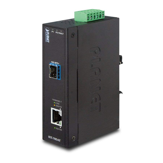
Page 11: Converter Front Panel And Led Indicators
5Gbps/100Mbps. Figure 2-1: IXT-705AT Front Panel 2.3 Converter Upper Panel The upper panel of the IXT-705AT consists of one terminal block connector within two DC power inputs. Figure 2-2 shows the upper panel of the IXT-705AT. 1 2 3 4 5 6... -
Page 12: Installation
3. Installation This section describes the functionalities of the Industrial Media Converter’s components and guides you to how to install it on the desktop. Basic knowledge of networking is assumed. Please read this chapter completely before continuing. 3.1 Quick Installation Steps Step 1: Unpack the Industrial Media Converter. -
Page 13: Mounting Installation
Manual uses IGS-801 (PLANET 8-port Industrial Gigabit Switch) as the example. However, the steps for PLANET Industrial Note Switch and Industrial Media Converter are similar. 3.2.1 DIN-rail Mounting The DIN rail is screwed on the Industrial Media Converter when is out of factory. -
Page 14: Wall-Mount Plate Mounting
Step 3: Make sure the DIN rail is tightly secured on the track. Step 4: Please refer to the following procedures to remove the Industrial Media Converter from the trac Step 5: Lightly pull out the bottom of the DIN rail from the track to remove. -
Page 15: Wiring The Power Inputs
Step 2: Place the wall-mount plate on the rear panel of the Industrial Media Converter. Step 3: Use the screws to screw the wall-mount plate on the Industrial Media Converter. Step 4: Use the hook holes at the corners of the wall-mount plate to hang the Industrial Media Converter on the wall. -
Page 16: Wiring The Fault Alarm Contact
2. Tighten the wire-clamp screws for preventing the wires from loos- ening. Power 1 Fault Power 2 The wire gauge for the terminal block should be in the range between 12 and 24 AWG. Note 3.4 Wiring the Fault Alarm Contact The fault alarm contacts are in the middle of the terminal block connector as the picture shows below. -
Page 17: Cable Connection
Industrial Media Converter MTB Series Transceiver Figure 3-1: Plug in the SFP+ Transceiver It is recommended to use PLANET SFP+s on the Indus- trial Media Converter. If you insert an SFP+ transceiver that is not supported, the Industrial Media Converter will Note not recognize it. - Page 18 1. Make sure both sides of the SFP+ transceiver are with the same media type; for example, 10GBASE-SR to 10GBASE-SR, 10GBASE-LR to 10GBASE-LR. 2. Check whether the fiber-optic cable type matches the SFP+ trans- ceiver model. To connect to 10GBASE-SR SFP+ transceiver, use the multi-mode fiber cable with one side being the male duplex LC connector type.
- Page 19 Never pull out the module without pulling the lever or the push bolts on the module. Directly pulling out the module with effort could damage the module and SFP+ Note module slot of the Industrial Media Converter. „ 100/1000/2500/5000/10000BASE-T 100/1000/2500/5000/10000BASE-T port comes with...
-
Page 20: Troubleshooting
4. Troubleshooting This chapter contains information to help you solve issues. If the Industrial Media Converter is not functioning properly, make sure the Industrial Media Converter is set up according to instructions in this manual. The per port LED is not lit Solution: Check the cable connection of the Industrial Media Converter. -
Page 21: Appendix A: Approved Planet Sfp+ Transceivers
APPENDIX A: Approved PLANET SFP+ Transceivers PLANET Industrial Media Converter supports 100/1000 dual mode with both single mode and multi-mode SFP+ transceivers. The following list of approved PLANET SFP+ transceivers is correct at the time of publication: Available 10Gbps Modules MTB-SR... -
Page 22: Appendix B: Networking Connection
APPENDIX B: Networking Connection B.1 Converter’s RJ45 Pin Assignments 1000Mbps, 1000BASE-T Contact MDI-X BI_DA+ BI_DB+ BI_DA- BI_DB- BI_DB+ BI_DA+ BI_DC+ BI_DD+ BI_DC- BI_DD- BI_DB- BI_DA- BI_DD+ BI_DC+ BI_DD- BI_DC- 100Mbps, 100BASE-TX RJ45 Connector Pin Assignment MDI-X Contact Media Dependent Media Dependent Interface Interface -- Cross Tx + (transmit) -
Page 23: Rj45 Cable Pin Assignments
B.2 RJ45 Cable Pin Assignments The standard RJ45 receptacle/connector There are 8 wires on a standard UTP/STP cable and each wire is color- coded. The following shows the pin allocation and color of straight cable and crossover cable connection: Straight Cable SIDE 1 SIDE 2 1 = White/Orange... -
Page 24: Ec Declaration Of Conformity
*Model Number : IXT-705AT * Produced by: Manufacturer Name : Planet Technology Corp. Manufacturer Address : 10F., No.96, Minquan Rd., Xindian Dist., New Taipei City 231, Taiwan, R.O.C. is herewith confirmed to comply with the requirements set out in the Council Directive on the Approximation of the Laws of the Member States relating to Electromagnetic Compatibility Directive on (2014/30/EU).
Need help?
Do you have a question about the IXT-705AT and is the answer not in the manual?
Questions and answers