
Related Manuals for Planet IGUP-805AT


Summary of Contents for Planet IGUP-805AT
- Page 1 Industrial 1-Port 100/1000X SFP to 1-Port 10/100/1000T 802.3bt PoE++ Media Converter IGUP-805AT Quick Installation Guide...
-
Page 2: Table Of Contents
Table of Contents 1. Package Contents ................. 3 2. Hardware Introduction ................4 2.1 Media Converter Front Panel ............4 2.2 LED Definition: ................5 2.3 Upper Panel .................. 6 2.4 Wiring the Power Inputs ..............7 2.5 Wiring the Fault Alarm Contact ............8 2.6 Grounding the Device .............. -
Page 3: Package Contents
1. Package Contents Thank you for purchasing PLANET Industrial 100/1000X to 10/100/1000T 802.3bt PoE++ Media Converter, IGUP-805AT. In the following sections, the term “Industrial PoE++ Media Converter” means the IGUP-805AT. Open the box of the Industrial PoE++ Media Converter and carefully unpack it. -
Page 4: Hardware Introduction
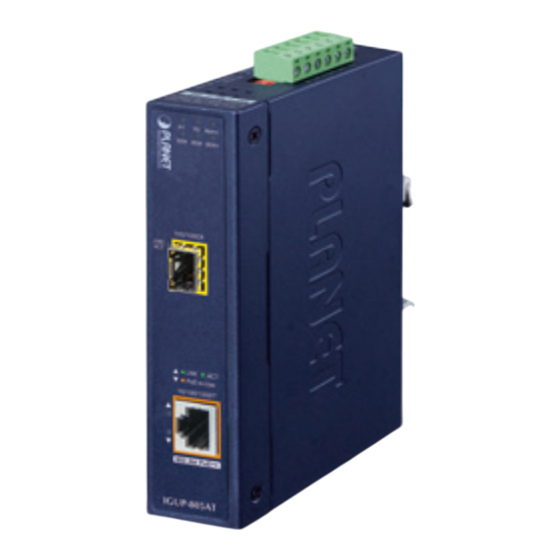
550 meters to 2km (multi-mode 100/1000X LNK/ fiber) and 10/20/30/40/60/80/120 kilometers (single-mode fiber). Gigabit TP Interface PoE-in-Use 10/100/1000T 10/100/1000BASE-T copper RJ45 twisted-pair with up to 100 meters in distance. 802.3bt PoE++ IGUP-805AT Figure 2-1: IGUP-805AT Front Panel... -
Page 5: Led Definition
2.2 LED Definition: System Color Function Green Lights to indicate power input 1 has power. Green Lights to indicate power input 2 has power. Lit: Indicates one or more of the following events are triggering the alarm (LED). Fiber Port PWR1 PWR2 Alarm LED Link Status Alarm DOWN... -
Page 6: Upper Panel
The upper panel of the Industrial PoE++ Media Converter consists of one terminal block connector within two power inputs, and also provides 2 DIP switches. Figure 2-2 shows the upper panel of the IGUP-805AT. Max. Fault Alarm Loading: 24V, 1A 1 2 3 4 5 6... -
Page 7: Wiring The Power Inputs
LFPP Enable Disable (default) Legacy BT (default) LFPP means Link Fault Passthrough PoE Control. 1. The IGUP-805AT will disable PoE port once it detects the fiber optic link is down. LFPP ON: 2. The IGUP-805AT will turn on fiber alarm. LFPP OFF: The IGUP-805AT LFPP is inactivated.(default) 2.4 Wiring the Power Inputs The 6-contact terminal block connector on the top panel of Industrial PoE++ Media Converter is used for two 12-54V DC redundant power inputs. -
Page 8: Wiring The Fault Alarm Contact
2. Tighten the wire-clamp screws for preventing the wires from loosening. Power 1 Alarm Power 2 1. The wire gauge for the terminal block should be in the range between 12 and 24 AWG. 2. The DC power input range is 12-54V DC. Note PWR1 and PWR2 must provide exactly the same DC voltage for power load balance while operating with dual power input. -
Page 9: Grounding The Device
1. The wire gauge for the terminal block should be in the range between 12 and 24 AWG. Note 2. Alarm relay circuit accepts up to 24V, max. 1A currents. 2.6 Grounding the Device Users MUST complete grounding wired with the device; otherwise, a sudden lightning could cause fatal damage to the device. EMD (Lightning) DAMAGE IS NOT CONVERED UNDER WARRANTY. -
Page 10: Hardware Installation
Converter’s components and guides you to installing it on the DIN rail and wall. Please read this chapter completely before continuing. This following pictures show the user how to install the device, and the device is not IGUP-805AT. Note 3.1 DIN-rail Mounting Installation... -
Page 11: Wall-Mount Plate Mounting
3.2 Wall-mount Plate Mounting 3.3 Side Wall-mount Plate Mounting You must use the screws supplied with the wall-mounting brackets. Damage caused to the parts by using incorrect screws would invalidate your warranty. Caution... -
Page 12: Product Specifications
4. Product Specifications Model IGUP-805AT Hardware Specifications Copper Port 1 x 10/100/1000BASE-T port 1 x 1000BASE-SX/LX/BX SFP interface SFP Port Compatible with 100BASE-FX SFP DIP Switch LFPP Enable Disable (default) Legacy BT (default) Dimensions 32 x 87 x 135 mm (W x D x H) Weight 447g 12-54V DC,... - Page 13 Power Over Ethernet PoE Standard IEEE 802.3bt Power over Ethernet Plus Plus 802.3bt PoE++: 95W PoE Power Output Legacy mode: 95W PoE Power Supply End-span + Mid-span Type End-span: 1/2 (-), 3/6 (+); Power Pin Assignment Mid-span: 4/5 (+), 7/8 (-) 95 watts@24-54V DC input PoE Power Budget 60 watts@12-23V DC input Standards Conformance Regulatory FCC Part 15 Class A, CE...
-
Page 14: Physical Dimensions
5. Physical Dimensions The IGUP-805AT Industrial PoE++ Media Converter dimensions (W x D x H): 32 x 87 x 135mm 163.00 40.00 40.00 28.00 48.80 28.00 28.00 28.00 18.00 18.00 28.00 53.50 53.50 18.00 46.50 48.80 39.70 30.00 97.10 87.80... -
Page 15: Fiber And Poe Installation
If there is any IEEE 802.3af/IEEE 802.3at/IEEE 802.3bt device needed to be powered on, the IGUP-805AT can easily do just that. The IGUP-805AT needs 12-54V DC input and it injects the DC power into the pin of the twisted-pair cable. -
Page 16: Customer Support
Customer Support Thank you for purchasing PLANET products. You can browse our online FAQ resource on PLANET web site first to check if it could solve your issue. If you need more support information, please contact PLANET support team. PLANET online FAQs: http://www.planet.com.tw/en/support/faq.php...
Need help?
Do you have a question about the IGUP-805AT and is the answer not in the manual?
Questions and answers