
Related Manuals for Planet IGT-1205AT


Summary of Contents for Planet IGT-1205AT
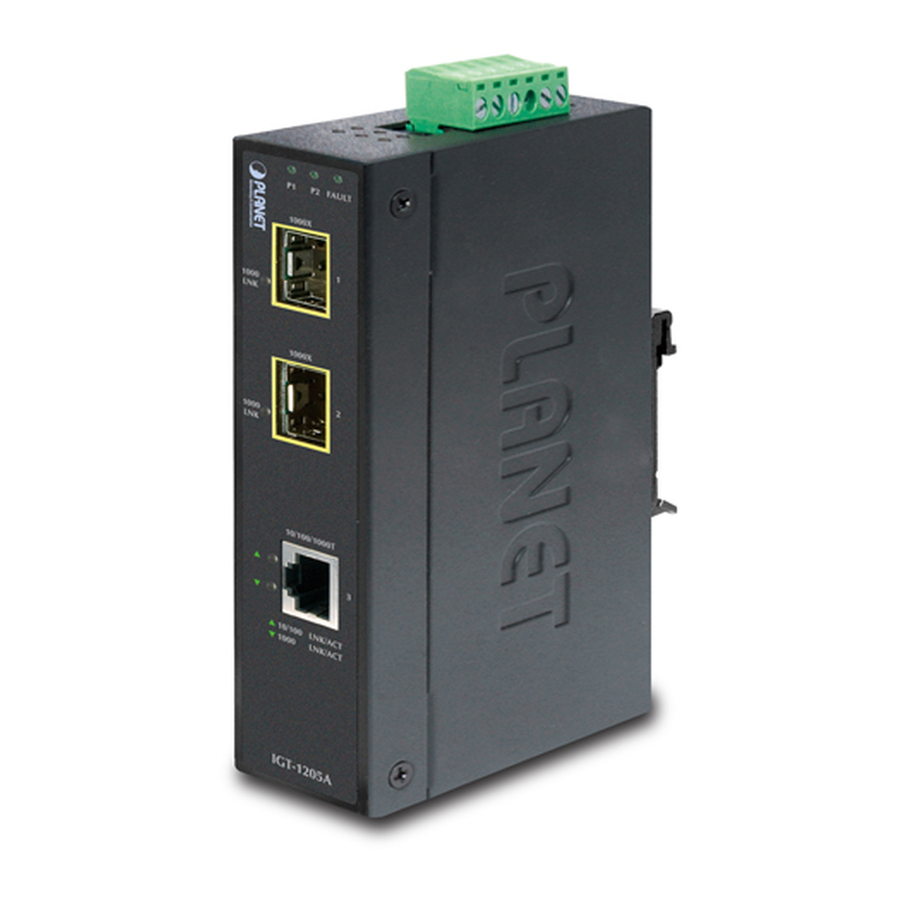
- Page 1 Industrial 10/100/1000Base-T to 2 100/1000Base-X SFP Media Converter IGT-1205AT User's Manual...
-
Page 2: Fcc Warning
PLANET is a registered trademark of PLANET Technology Corp. other trademarks belong to their respective owners. Disclaimer PLANET Technology does not warrant that the hardware will work properly in all environments and applications, and makes no warranty and representation, either implied or expressed, with respect to the quality, performance, merchantability, or fitness for a particular purpose. - Page 3 Do not dispose of WEEE as unsorted municipal waste and have to collect such WEEE separately. Revision PLANET Industrial 10/100/1000Base-T to 2 100/1000Base-X SFP Media Converter User's Manual For Model: IGT-1205AT Revision: 1.0 (APRIL, 2013) Part No: EM-IGT_1205AT_v1.0 (2350-AH1210-000)
-
Page 4: Table Of Contents
Table of Contents 1. Introduction ................5 1.1 Package Contents ..............5 1.2 How to Use This Manual ............5 1.3 Product Features ..............6 1.4 Product Specifications ............7 1.5 Physical Dimensions ............9 2. Installation ................10 2.1 Product Description ............10 2.1.1 Converter Front Panel ..........12 2.1.2 LED Indicators ............13 2.1.3 Converter Upper Panel ..........14... -
Page 5: Introduction
The term “Industrial Gigabit Media Converter” mentioned in this user’s manual also means the IGT-1205AT. 1.2 How to Use This Manual This... -
Page 6: Product Features
1.3 Product Features Physical Port 1-port 10/100/1000Base-T RJ-45 with auto MDI / MDI-X function 2 SFP interfaces, 100/1000Base-X dual mode (DIP switch control) Layer 2 Features IEEE 802.3 / 802.3u / 802.3ab / 802.3z Ethernet Standard Compliant ... -
Page 7: Product Specifications
When Primary-Port link fails, the traffic will swap to Backup-Port automatically Once the Primary-Port status is back to link up, the traffic will swap from Backup-Port to Primary-Port 1.4 Product Specifications Model IGT-1205AT Hardware Specification 10/100/1000Base-T Ports 2 1000Base-SX/LX/BX SFP interfaces SFP Interfaces... - Page 8 10/100/1000Base-T : Cat. 3, 4, 5, 5e, 6 UTP cable (100meters, max.) EIA/TIA-568 100-ohm STP (100meters, max.) 1000Base-SX : 50/125μm or 62.5/125μm multi-mode fiber optic cable, up to 550m (vary on SFP module) Network Cables 1000Base-LX : 9/125μm single-mode fiber optic cable, up to 10/20/30/40/50/70/120 kilometers (vary on SFP module) 100Base-FX :...
-
Page 9: Physical Dimensions
1.5 Physical Dimensions IGT-1205AT Industrial Gigabit Media Converter dimensions (W x D x H): 135 x 87 x 32mm Side View PWR1 Fault PWR2 Port 1 Port 2 Mode 100FX 1000X 100FX 1000X Redundant Switch Front View... -
Page 10: Installation
Adjustable 3-Port Switch Mode or 2 Fiber Port Redundant Mode Via the built-in DIP-switch, the two SFP fiber interfaces of IGT-1205AT can be configured as Ethernet switch mode or Fiber Redundant mode. With the Ethernet switch mode, it can operate Store-and-Forward mechanism with high performance;... - Page 11 Being able to operate under the temperature range from -40 to 75 degrees C, the IGT-1205AT can be placed in almost any difficult environment. The compact IP30 standard metal case of IGT-1205AT allows either DIN rail or wall mounting for efficient use of cabinet space.
-
Page 12: Converter Front Panel
2.1.1 Converter Front Panel Figure 2-1 shows the front panel of Industrial Gigabit Media Converter. P2 FAULT 1000X LNK / 1000X LNK / 10/100/1000T LNK/ACT 1000 LNK/ACT IGT-1205AT Figure 2-1: IGT-1205AT Front Panel... -
Page 13: Led Indicators
2.1.2 LED Indicators System Color Function Green Lit: indicate power 1 has power. Green Lit: indicate power 2 has power. Lit: indicate either power 1 or power 2 has no FAULT Green power. Per 10/100/1000T Port Color Function Lit: indicate the link through that port is successfully established at 100Mbps or 10Mbps. -
Page 14: Converter Upper Panel
2.1.3 Converter Upper Panel The upper panel of the Industrial Gigabit Media Converter consists of one terminal block connector within two DC power inputs, and also provides 3 DIP Switches for 100/1000X fiber support on two SFP slots and fiber redundant function. Figure 2-2 shows the upper panel of the Industrial Gigabit Media Converter. -
Page 15: Wiring The Power Inputs
2.1.4 Wiring the Power Inputs The 6-contact terminal block connector on the top panel of Industrial Gigabit Media Converter is used for two DC redundant power inputs. Please follow the steps below to insert the power wire. Insert positive / negative DC power wires into contacts 1 and 2 for POWER 1, or 5 and 6 for POWER 2. -
Page 16: Wiring The Fault Alarm Contact
2.1.5 Wiring the Fault Alarm Contact The fault alarm contacts are in the middle of the terminal block connector as the picture shows below. Inserting the wires, the Industrial Gigabit Media Converter will detect the fault status of the power failure and then forms an open circuit. The following illustration shows an application example for wiring the fault alarm contacts. - Page 17 The Industrial Gigabit Media Converter has two SFP interfaces that supports 100/1000 dual speed mode (Optional Multi-mode / Single- mode 100Base-FX / 1000Base-SX/LX SFP module) through DIP switch setting. Cabling The 10/100/1000Base-T port uses RJ-45 socket -- similar to phone jack -- for connection of unshielded twisted-pair cable (UTP).
- Page 18 MGB / MFB Series Transceiver Figure 2-3: Plug in the SFP Transceiver Approved PLANET SFP Transceivers PLANET Industrial Gigabit Media Converter supports 100/1000 dual mode with both Single mode and Multi-mode SFP transceivers. The following list of approved PLANET SFP transceivers is correct at the time of publication: Gigabit SFP Transceiver Modules MGB-GT...
- Page 19 SFP-Port 1000Base-LX (WDM, TX:1550nm) mini-GBIC MGB-LB40 module-40km SFP-Port 1000Base-SX mini-GBIC module - 550m MGB-TSX (-40~75°C) SFP-Port 1000Base-LX mini-GBIC module - 10km MGB-TLX (-40~75°C) SFP-Port 1000Base-LX mini-GBIC module - 30km MGB-TL30 (-40~75°C) SFP-Port 1000Base-LX mini-GBIC module - 70km MGB-TL70 (-40~75°C) Fast Ethernet SFP Transceiver Modules MFB-FX SFP-Port 100Base-FX Transceiver (1310nm) - 2km MFB-F20...
- Page 20 1. Set the DIP Switch of SFP Port 1 or Port 2 to the “OFF” position with fiber speed 1000Base-X. Port 1 (DIP 1) 100FX 1000X Port 2 (DIP 2) 100FX 1000X 2. Make sure both sides of the SFP transceiver are with the same media type;...
- Page 21 2. Make sure both sides of the SFP transceiver are with the same media type or WDM pair; for example, 100Base-FX to 100Base-FX, 100Base-BX20-U to 100Base-BX20-D. 3. Check the fiber-optic cable type match the SFP transceiver model. To connect to MFB-FX SFP transceiver, use the multi-mode fiber cable with one side being the male duplex LC connector type.
-
Page 22: Redundancy Overview
Never pull out the module without pulling the lever or the push bolts on the module. Directly pulling out the module with violence could damage the module and SFP Note module slot of the Industrial Gigabit Media Converter. 2.1.7 Redundancy Overview The Industrial Gigabit Media Converter provides rapid fiber redundancy of link for highly critical Ethernet applications. -
Page 23: Mounting Installation
2.2 Mounting Installation This section describes how to install the Industrial Gigabit Media Converter and makes connections to it. Please read the following topics and perform the procedures in the order being presented. installation steps below, this Manual uses IGS-801 (PLANET 8 Port Industrial Gigabit Switch) as the example. - Page 24 Step 2: Lightly insert the DIN-Rail into the track. Step 3: Make sure the DIN-Rail is tightly secured on the track. Step 4: Please refer to the following procedures to remove the Industrial Gigabit Media Converter from the track.
-
Page 25: Wall Mount Plate Mounting
Step 5: Lightly pull out the bottom of the DIN-Rail from the track to remove. 2.2.2 Wall Mount Plate Mounting To install the Industrial Gigabit Media Converter on the wall, please follow the instructions described below. Step 1: Remove the DIN-Rail from the Industrial Gigabit Media Converter;... -
Page 26: Applications
3. Applications In this paragraph, we will describe how to install the Industrial Gigabit Media Converter. Transportation Networking Fiber Switch Serial over IGT-1205AT Ethernet Device 20km 50km 1000 IGT-1205AT Control Center 120km 1000 Outdoor IGT-1205AT IP Camera Robot ROBOT ROBOT... - Page 27 Installation Steps Step 1: Unpack the Industrial Gigabit Media Converter. Step 2: Check whether the DIN-Rail is screwed on the Industrial Gigabit Media Converter. (Please refer to DIN-Rail Mounting section for DIN-Rail installation if the DIN-Rail is not screwed on the Industrial Gigabit Media Converter). If you want to wall-mount the Industrial Gigabit Media Converter, then please refer to the Wall Mount Plate Mounting section for wall mount plate installation.
-
Page 28: Troubleshooting
4. Troubleshooting This chapter contains information to help you solve issues. If the Industrial Gigabit Media Converter is not functioning properly, make sure the Industrial Gigabit Media Converter is set up according to instructions in this manual. The per port LED is not lit Solution: Check the cable connection of the Industrial Gigabit Media Converter. -
Page 29: Cable Connection Parameters
(MHz * km) (meters) 62.5 62.5 1000Base- SX 62.5 1000Base- LX 5000* The Single-mode port (1000Base-LX port) of IGT-1205AT complies with LX 5 kilometers and provides additional margin allowing for a 10/20/30/40/50/70/120 kilometer Note Gigabit Ethernet link on single mode fiber. -
Page 30: Appendix A: Networking Connection
APPENDIX A: Networking Connection A.1 Converter’s RJ-45 Pin Assignments 1000Mbps, 1000Base-T Contact MDI-X BI_DA+ BI_DB+ BI_DA- BI_DB- BI_DB+ BI_DA+ BI_DC+ BI_DD+ BI_DC- BI_DD- BI_DB- BI_DA- BI_DD+ BI_DC+ BI_DD- BI_DC- 10/100Mbps, 10/100Base-TX RJ-45 Connector pin assignment MDI-X Contact Media Dependant Interface- Media Dependant Interface Cross Tx + (transmit) -
Page 31: Cable Pin Assignments
A.2 RJ-45 Cable Pin Assignments The standard RJ-45 receptacle/connector There are 8 wires on a standard UTP/STP cable and each wire is color- coded. The following shows the pin allocation and color of straight cable and crossover cable connection: Straight Cable SIDE 1 SIDE 2 SIDE 1... -
Page 32: Ec Declaration Of Conformity
: Industrial 10/100/1000Base-T to 2 100/1000Base-X SFP Media Converter (-40~75 degrees C) *Model Number : IGT-1205AT * Produced by: : Planet Technology Corp. Manufacturer Name Manufacturer Address : 10F., No.96, Minquan Rd., Xindian Dist., New Taipei City 231, Taiwan (R.O.C.)
Need help?
Do you have a question about the IGT-1205AT and is the answer not in the manual?
Questions and answers