
Related Manuals for Planet ICS-2100


Summary of Contents for Planet ICS-2100
- Page 1 User’s Manual ICS-2100 ICS-2102 ICS-2102S15 Industrial RS-232/RS-422/RS-485 over 100Base-FX / 10/100Base-TX Media Converter...
-
Page 2: Fcc Warning
Copyright © PLANET Technology Corp. 2009. Contents subject to which revision without prior notice. PLANET is a registered trademark of PLANET Technology Corp. All other trademarks belong to their respective owners. Disclaimer PLANET Technology does not warrant that the hardware will work properly in all environments and applications, and makes no warranty and representation, either implied or expressed, with respect to the quality, performance, merchantability, or fitness for a particular purpose. -
Page 3: Table Of Contents
User’s Manual of ICS-210x TABLE OF CONTENTS 1. INTRODUCTION ......................1 1.1 P ..........................1 ACKAGE ONTENTS 1.2 H ......................... 1 OW TO ANUAL 1.3 P ..........................1 RODUCT ESCRIPTION 1.4 A ............................2 PPLICATIONS 1.5 P ..........................4 RODUCT EATURES 1.6 P .......................... - Page 4 User’s Manual of ICS-210x 4.4.3 UDP Client Mode .............................. 32 4.4.4 Virtual COM Mode............................. 33 4.4.5 Telnet Server Mode............................40 4.4.6 Pair Connection– Local Mode ........................... 44 4.4.7 Pair Connection – Remote Mode ........................45 4.5 S ........................49 ERIAL ONFIGURATION 4.6 SMTP..............................
-
Page 5: Introduction
User’s Manual of ICS-210x 1. INTRODUCTION Thank you for purchasing PLANET Industrial RS-232/RS-422/RS-485 over 10/100Base-TX/100Base-FX Media Converter – ICS-210x series. Terms of “Industrial Serial Converter” means the products mentioned titled in the cover page of this User’s manual. 1.1 Package Contents Open the box of the Industrial Serial Converter and carefully unpack it. -
Page 6: Applications
User’s Manual of ICS-210x The ICS-210x make connected Serial equipment becomes IP-based. That also makes them be able to connect to a TCP/IP networking immediately. Each Web-Smart converter is able to manage through the Web Interface. The powerful Web-Smart Media Converter supports Application mode, Serial operation mode connect alarm and IP address, etc. Management function helps reduce the amount of valuable time that a network administrator spends detecting and locating network problems, otherwise it requires visual inspection of cabling and equipment. - Page 7 User’s Manual of ICS-210x Process Control To monitor, configure and manage the Robot conveyer including other machines in a manufacturing, PLC (Programmable Logical Control) is required. The PLC is used to drive above the manufacturing machines process. The ICS-210x can be set to TCP Server mode and connect the PLC.
-
Page 8: Product Features
Ethernet Interface Complies with IEEE 802.3, IEEE 802.3u 10/100Base-TX, 100Base-FX standard Supports auto MDI/MDI-X function on RJ-45 Port for ICS-2100 Supports 100Base-FX multi-mode SC concocter up to 2km for ICS-2102 Supports 100Base-FX single-mode SC concocter up to 15km for ICS-2102S15... -
Page 9: Product Specification
Supports EFT protection 6000 VDC for power line Supports 6000 VDC Ethernet ESD protection -10 to 60 Degree C operation temperature 1.6 Product Specification Model ICS-2100 ICS-2102 ICS-2102S15 Serial Port RS-232 x 1 Interface RS-422 / RS-485 x 1... - Page 10 User’s Manual of ICS-210x UDP Client Virtual COM Telnet Server Pair Connection – Remote (Slave) Pair Connection – Local (Master) Dimension(W x D x H) 135 x 97 x 32 mm Weight 425g 431g Power Supply 12~48V DC, Redundant power with polarity reverse protection function Power Consumption 10.1 Watts / 34.44 BTU (max) Installation...
-
Page 11: Hardware Installation
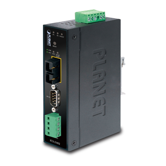
Figure 2-1 to Figure 2-2 show front panel of ICS-210x. ICS-2100 ICS-2102 / ICS-2102S15 – RS-232 / RS-422 / RS-485 over 10/100Base-TX – RS-232 / RS-422 / RS-485 over 10/100Base-FX Figure 2-1 PLANET ICS-2100 Front Panel Figure 2-2 PLANET ICS-2102/2102S15 Front Panel... -
Page 12: Led Indicators
User’s Manual of ICS-210x 2.1.2 LED Indicators Color Function Green Indicate the power 1 has power. Green Indicate the power 2 has power. FAULT Green Indicate the either power 1 or power 2 has no power. To indicate that the Fast Ethernet Port is successfully connecting to the Lights TP or Fiber Green... -
Page 13: Industrial Serial Converter Upper Panel
User’s Manual of ICS-210x 2.1.4 Industrial Serial Converter Upper Panel The upper panel of the Industrial Serial Converter consist one terminal block connector within two DC power inputs. Figure 2-3 shows the upper panel of the industrial serial converter. Figure 2-3 Industrial Serial Converter upper Panel. 2.1.5 Wiring the Power Inputs The 6-contact terminal block connector on the top panel of Industrial Serial Converter is used for two DC redundant powers input. -
Page 14: Wiring The Fault Alarm Contact
User’s Manual of ICS-210x 2. Tighten the wire-clamp screws for preventing the wires from loosing. Figure 2-5 shows PWR1 and PWR2 pin of the terminal block. Power 1 Fault Power 2 Figure 2-5 PWR1 & PWR2 pin of terminal block. The wire gauge for the terminal block should be in the range between 12 ~ 24 AWG. -
Page 15: Mounting Installation
User’s Manual of ICS-210x The wire gauge for the terminal block should be in the range between 12 ~ 24 AWG. Alarm relay circuit accepts up to 30V, max. 3A currents. Figure 2-7 Fault alarm contact. 2.2 Mounting Installation This section describes how to install the Industrial Equipment and make connections to it. Please read the following topics and perform the procedures in the order being presented. -
Page 16: Remove Din-Rail Mounting
User’s Manual of ICS-210x Step 2: Check the DIN-Rail is tightly on the track. Figure 2-9 shows that install Industrial Equipment finish in DIN-Rail mount. Figure 2-9 Industrial Equipment installed in DIN-Rail mount. 2.2.2 Remove DIN-Rail Mounting Step 1: Please refer to following procedures to remove the Industrial Equipment from the track. Figure 2-10 shows how to remove Industrial Equipment in DIN-Rail mount. -
Page 17: Wall Mount Plate Mounting
User’s Manual of ICS-210x 2.2.3 Wall Mount Plate Mounting To install the Industrial Equipment on the wall, please follows the instructions described below. Step 1: Remove the DIN-Rail from the Industrial Equipment; loose the screws to remove the DIN-Rail. Step 2: Place the wall mount plate on the rear panel of the Industrial Equipment. Figure 2-11 shows how to attach brackets to one side of the Industrial Equipment. - Page 18 User’s Manual of ICS-210x Figure 2-12 ICS-2100 stand alone installation Figure 2-13 ICS-2102 / ICS-2102S15 stand alone installation Please refers to APPENDIX-A for detailed wiring information of the ICS-210x. To prevent from optic acceptor malfunction, check the both wires / transmitter before power on the converter.
-
Page 19: Industrial Media Converter Management
Please refer to the following Chapter 4 for more details. 3.2 Requirements ■ Network cables. For ICS-2100: Use standard network (UTP) cables with RJ-45 connectors. For ICS-2102 / ICS-2102S15: Use Multi-mode or Single-mode fiber patch cord with SC connectors. ■ Subscriber PC installed with Ethernet NIC (Network Card) ■... -
Page 20: Management Methods
User’s Manual of ICS-210x 3.3 Management Methods The way to manage the ICS-210x: - Web Management via a network or dial-up connection 3.3.1 Web Management The PLANET Industrial Web-Smart Serial Converter provides a built-in browser interface. You can manage the ICS-210x remotely by having a remote host with web browser, such as Microsoft Internet Explorer, Netscape Navigator or Mozilla Firefox. - Page 21 User’s Manual of ICS-210x Figure 3-2 Login screen For security reason, please change and memorize the new password after this first setup. Only accept command in lowercase letter under web interface. -17-...
-
Page 22: Web Management
User’s Manual of ICS-210x 4. WEB MANAGEMENT The ICS-210x Industrial Web Smart Serial Converter provide Web interface for Converter smart function configuration and make the Converter operate more effectively - They can be configured through the Web Browser. A network administrator can manage and monitor the ICS-210x from the local LAN. -
Page 23: System
User’s Manual of ICS-210x 4.2 System 4.2.1 System Information The System Information page provides information for the current device. System Info page helps a network manager to identify the versions and IP Address etc. The screen in Figure 4-2 appears. Figure 4-2 System Information screen The page includes the following fields: •... -
Page 24: Password Setting
User’s Manual of ICS-210x 4.2.2 Password Setting This function provides administrator to secure Web login. The screen in Figure 4-3 appears. Figure 4-3 Password Setting screen The page includes the following configurable data: Login Name Displays the user name. New Password Specifies the new password. -
Page 25: Firmware Upgrade
User’s Manual of ICS-210x The page includes the following configurable data: Object Description Tick the check box to enable the function of lighting up the FAULT LED on the panel when Power Failure: power fails. 4.2.4 Firmware upgrade The Firmware Upgrade page contains fields for downloading system image files from the Local File browser to the device. The screen in Figure 4-5 appears. - Page 26 User’s Manual of ICS-210x Then the “Firmware Upgrade Mode” displayed as in Figure 4-7. Figure 4-7 Firmware Upgrade screen Click the “Browse” button of the main page, the system would pop up the file selection menu to choose firmware. Figure 4-8 Windows file selection menu popup Select on the firmware then click “Upgrade”.
-
Page 27: Factory Default
User’s Manual of ICS-210x Do not quit the Firmware Upgrade page without press the “Upgrade” button - after the image is loaded. Or the system won’t apply the new firmware. Users have to repeat the firmware upgrade processes again. 4.2.5 Factory Default The Factory Default can reset the ICS-210x back to the factory default mode. -
Page 28: Network Configuration
User’s Manual of ICS-210x 4.3 Network Configuration This function allows setting the value for network configuration. The value is DHCP client, IP address, Subnet Mask, Gateway, DNS and system name. Press the “Apply” button to set the value. The screen in Figure 4-11 appears. Figure 4-11 Network Configuration screen The page includes the following configurable data: •... -
Page 29: Operation Mode
User’s Manual of ICS-210x 4.4 Operation Mode The ICS-210x make connected Serial equipment becomes IP-based. That also makes them be able to connect to a TCP/IP networking immediately. The ICS-210x allow traditional Computer/Client COM ports access to a serial equipment anywhere on the Ethernet LAN network. - Page 30 User’s Manual of ICS-210x Figure 4-13 TCP Server mode The screen in Figure 4-13 appears. When the changed operation mode, the user should be changed the Serial Port Configuration. Figure 4-14 TCP Server Configuration screen The page includes the following fields: •...
- Page 31 User’s Manual of ICS-210x Example: Use Microsoft Windows Hyper Terminal, TCP/IP Winsock mode HyperTerminal is a program that you can use to connect to other computers, Telnet sites, online services, and host computers, using your modem, a null modem cable, a Console cable or Ethernet connection. The users want to use the TCP Server mode to connect to a Ethernet Switch via Hyper Terminal, Winsock mode Setup Operation Mode and Serial Port of ICS-210x Hyper Terminal set up a new connection with the TCP/IP Winsock...
- Page 32 User’s Manual of ICS-210x Figure 4-16 Example: Serial Port Configuration screen Hyper Terminal setup a new connection with TCP/IP Winsock Open HyperTerminal Figure 4-17 Example: Hyper Terminal screen -28-...
- Page 33 User’s Manual of ICS-210x On the File menu, click New Connection. In the Name box, type a name that describes the connection. In the Icon box, click the appropriate icon, and then click OK. Figure 4-18 Example: Hyper Terminal – Create new connection In the Connect To dialog box, choose which port or modem you want to use in the Connect using drop-down box.
- Page 34 User’s Manual of ICS-210x Figure 4-20 Example: Hyper Terminal configuration Value Description Host address The address or name of the connection you want to create. This can be in standard Internet dotted notation (for example, w.x.y.z) or can be the site's user-friendly name. port The number of the port that you want the connection to use.
-
Page 35: Tcp Client Mode
User’s Manual of ICS-210x 4.4.2 TCP Client Mode When the ICS-210x be configured to TCP Client mode, it allows Serial device that connected to serial port of ICS-210x to establish TCP communication actively over Intranet or Internet network between: Remote Host (Computer) with Serial applications using TCP/IP network socket programs Other ICS-210x with TCP Server mode After the data has been transferred, the ICS-210x can disconnect automatically from the Remote Host depends on the TCP Inactive timeout settings. -
Page 36: Udp Client Mode
User’s Manual of ICS-210x 4.4.3 UDP Client Mode When the ICS-210x be configured to UDP Client mode, it allows Serial device that connected to serial port of ICS-210x to quickly transmit data to multiple Remote Hosts over Intranet or Internet network by unicast or multicast. It also makes the Serial device to receive data from more than one Remote Hosts. -
Page 37: Virtual Com Mode
User’s Manual of ICS-210x The page includes the following fields: • Local UDP Port Enter the local port number • Remote Address Enter the IP address of the remote device. • Remote Port Enter the remote port number of the remote device. 4.4.4 Virtual COM Mode When the ICS-210x be configured to Virtual COM mode, it allows Serial device that connected to serial port of ICS-210x to establish TCP communication over Intranet or Internet network between Remote Host (Computer). - Page 38 User’s Manual of ICS-210x The page includes the following fields: • TCP Port Number The TCP port that ICS-210x uses to listen to connections and that other device must use to contact ICS-210x. To avoid conflicts with well known TCP ports, the default is set to “1024”.
- Page 39 User’s Manual of ICS-210x Set the Serial Port Configuration of ICS-210x as below: Mode: RS-232 Baudrare: 9600 Character Bits: Parity Type : none Stop Bit : Hardware Flow Control: none Figure 4-30 Example: Serial Port Configuration screen -35-...
- Page 40 User’s Manual of ICS-210x VCOM Utility to create virtual COM port This mode will run with the software-“PLANET VCOM Utility”. Open the VCOM utility; click “Search” button to point out the ICS-210x that want to be configured. Figure 4-31 Example: Virtual COM Configuration screen Choose the COM Mapping and add COM 9 like below: -36-...
- Page 41 User’s Manual of ICS-210x Figure 4-32 Example: Virtual COM Configuration screen Hyper Terminal setup a new connection with virtual COM port On the File menu, click New Connection. In the Name box, type a name that describes the connection. In the Icon box, click the appropriate icon, and then click OK. Figure 4-33 Example: HyperTerminal Configuration screen In the Connect to dialog box, choose which port you want to use in the Connect using drop-down box.
- Page 42 User’s Manual of ICS-210x Figure 4-34 Example: HyperTerminal Configuration screen Set the parameter like below, click “Apply” to take effect. Figure 4-35 Example: HyperTerminal COM port properties screen After the Virtual COM connection is established, open the VCOM utility again to check the COM9 information. -38-...
- Page 43 User’s Manual of ICS-210x Figure 4-36 Example: VCOM Utility, COM9 information Then can use the console like connect the serial cable with the switch. Figure 4-37 Example: Hyper Terminal COM port screen -39-...
-
Page 44: Telnet Server Mode
User’s Manual of ICS-210x 4.4.5 Telnet Server Mode TELNET (TELecommunication NETwork) is a network protocol used on the Internet or local area network (LAN) connections. The Telnet protocol type is the correct setting for most servers and serial devices, such as Managed Ethernet switches or Gateways. - Page 45 User’s Manual of ICS-210x Example 1: Telnet Command in Windows Platform Figure 4-40 Example Telnet Server Setup Operation Mode and Serial Port of ICS-210x Set the ICS-210x mode to “Telnet server mode” from web interface. Set the Serial Port Configuration of ICS-210x as below: Mode: RS-232 9600...
- Page 46 User’s Manual of ICS-210x While the Telnet window appears, type “open xxx,xxx,xxx,xxx”, xxx is the IP address of the ICS-210x Telnet Server. In this case we type “open 192.168.0.100” and press enter. Figure 4-42 Example Windows Excuse - Telnet Then can use the telnet connection to configure the switch just like console direct connect to the COM port of the switch. Figure 4-43 Example Windows Excuse - Telnet To quit the Telnet session, press “CTRL+]”...
- Page 47 User’s Manual of ICS-210x Example 2: Putty software in Windows Platform PuTTY is a free implementation of Telnet and SSH for Win32 and Unix platforms, along with an xterm terminal emulator. In this case we use Putty to telnet to the ICS-210x-Telnet Server mode for remote console login. Set the ICS-210x mode to “Telnet server mode”...
-
Page 48: Pair Connection- Local Mode
User’s Manual of ICS-210x 4.4.6 Pair Connection– Local Mode The parameter defines the maintenance status for listen for the pair connection To make a long distance communication between two serial equipment, configure two ICS-210x with Pair Connection mode and setup one as a Master (Local side) and the other as a Slave (Remote side). -
Page 49: Pair Connection - Remote Mode
User’s Manual of ICS-210x 4.4.7 Pair Connection – Remote Mode The parameter defines the maintenance status for listen for the pair connection In effect, this converter will be acting as a TCP client. The screen in Figure 4-49 appears. When the changed operation mode, the user should be changed the Serial Port Configuration. Figure 4-49 Pair Connection –... - Page 50 User’s Manual of ICS-210x Example: Two ICS-210x with Pair Connection mode One be configured as Pair Connection – Local (Master) The other one be configured as Pair Connection – Remote (Slave) Via the RS-485 interface, the external scanners, speed dome cameras and PTZ receivers can be controlled by the keyboard which provides upward, downward, leftward, rightward, clockwise and counterclockwise with the joystick.
- Page 51 User’s Manual of ICS-210x Connect the converter with the IP camera for RS-485 interface like PLANET product: “ICA-601”. Connect the converter with the control keyboard for RS-485 interface like PLANET product: “CAM-KB300”. ICS-210x – Master: be configured as Pair-Connection-Local From Web interface, login the ICS-210x with IP address = 192.168.0.100, set up the operation mode of this unit to be “...
- Page 52 User’s Manual of ICS-210x ICS-210x – Slave: be configured to Pair-Connection-Remote From Web interface, login the ICS-210x with IP address = 192.168.0.101, set up the operation mode of this unit to be “ Pair Connection-Local (Slave)” Figure 4-53 Pair Connection –Remote, operation mode configuration Set the Serial Port mode of ICS-210x-Slave to RS-485.
-
Page 53: Serial Port Configuration
User’s Manual of ICS-210x 4.5 Serial Port Configuration The page shows the converter’s serial Port configuration. The screen in Figure 4-55 appears. Figure 4-55 Serial Port Configuration page screen The page includes the following fields: • Mode From the drop-down menu, select the serial port mode: RS-232 RS-422 RS-485... - Page 54 User’s Manual of ICS-210x none, HW The default value is “none”. • Delimiter Character The Character 1 and Character 2 allow the use to enter two ASCII character (in hex format) that delimit the beginning and end of a message. When a message with both there delimiters is received at the serial port, the data contained in the serial buffer is paced in an Ethernet packet and sent out the Ethernet port.
-
Page 55: Smtp
User’s Manual of ICS-210x 4.6 SMTP The page shows SMTP configuration. The screen in Figure 4-56 appears. You may setup SMTP mail parameters for further operation. That’s, if users want to send the alarm message out that contains “Log-Fail Warring”, “OP Change Warning” and “Reboot Warning”, it will need to configure parameters here. - Page 56 User’s Manual of ICS-210x The page includes the following fields: SMTP Setup • Enable SMTP To Enable SMTP function. The default value is “Disable”. Set port number of SMTP service. The default number is “25”. • SMTP Port Type the SMTP server name or the IP address of the SMTP server address •...
- Page 57 User’s Manual of ICS-210x Figure 4-58 Login screen -53-...
-
Page 58: Software Vcom Utility
User’s Manual of ICS-210x 5. SOFTWARE VCOM UTILITY The ICS-210x Web Smart Media Converter provides software for Converter smart function configuration when the Converter operation mode on “Virtual COM”. - They can be configured through the Console. Two function groups are provide to easy used, can search device and create virtual COM to view as the console port. - Page 59 User’s Manual of ICS-210x Click Install to install the program. Figure 5-2 VCOM installation screen The Installing window reports the progress of the installation. Click Finish to complete Figure 5-3 VCOM installation screen -55-...
- Page 60 User’s Manual of ICS-210x To run the PLANET VCOM utility on the computer, click “Start” \ “All Programs” \ “PLANET” \ “VCOM” \ “VCOM” Figure 5-4 VCOM program path -56-...
-
Page 61: Search The Device
User’s Manual of ICS-210x 5.2 Search the Device Click the Search button to find the ICS-210x. It will show the ICS-210x device name, project number, MAC address and IP address. Click the shortcut of VCOM on the desktop to run the VCOM program. Click "Search"... -
Page 62: Virtual Com
User’s Manual of ICS-210x 5.3 Virtual COM This function should be set the ICS-210x’s operation mode to “Virtual COM” on the Web. Choose to create port like below: If the device support Telnet, while user click “COM Mapping”. Figure 5-6 COM Mapping While user click “Add”... - Page 63 User’s Manual of ICS-210x Select device which user want and set up “TCP”,“Client” mode, “COM” number and “RemotePort” number. Click "OK" button to create new virtual com port and establish telenet connection Figure 5-8 Add Virtual COM Port Configuration Then set the HyperTerminal parameter Figure 5-9 Hyper Terminal Configuration -59-...
- Page 64 User’s Manual of ICS-210x then the VCOM will show connect information like below: Figure 5-10 VCOM Configuration Once the Virtual COM Port- COM9 connection is established, from the Windows Device Manager, a COM Port is added to the device list. Figure 5-11 Windows Device Server - Virtual COM Port When the Virtual COM creates COM port, the Device Manager will add “Virtual Serial Port”.
-
Page 65: Planet Smart Discovery Utility
User’s Manual of ICS-210x APPENDIX A A.1 PLANET Smart Discovery Utility For easily list the ICS-210x in your Ethernet environment, the Planet Smart Discovery Utility from user’s manual CD-ROM is an ideal solution. The following install instructions guiding you for run the Planet Smart Discovery Utility. 1. -
Page 66: Device Srj-232/Rs-422/Rs-485 Pin Assignments
User’s Manual of ICS-210x 1. This utility show all necessary information from the devices, such as MAC Address, Device Name, firmware version, Device IP Subnet address, also can assign new password, IP Subnet address and description for the devices. 2. After setup completed, press “Update Device”, “Update Multi” or “Update All” button to take affect. The meaning of the 3 buttons above are shown as below: Update Device: use current setting on one single device. -
Page 67: Device Srj-45 Pin Assignments
User’s Manual of ICS-210x A.3 Device‘s RJ-45 Pin Assignments 10/100Mbps, 10/100Base-TX ■ Contact MDI-X 1 (TX +) 2 (TX -) 3 (RX +) 6 (RX -) 4, 5, 7, 8 Not used Not used Implicit implementation of the crossover function within a twisted-pair cable, or at a wiring panel, while not expressly forbidden, is beyond the scope of this standard. -
Page 68: Fiber Optical Cable Connection Parameter
User’s Manual of ICS-210x Please make sure your connected cables are with same pin assignment and color as above picture before deploying the cables into your network. A.5 Fiber Optical Cable Connection Parameter The wiring details are as below: Fiber Optical patch Cables: (For ICS-2102 / ICS-2102S) ■... -
Page 69: Ec Declaration Of Conformity
15 * Produced by: Manufacturer‘s Name : Planet Technology Corp. Manufacturer‘s Address : 11F, No. 96, Min Chuan Road, Hsin Tien, Taipei, Taiwan, R.O.C. is herewith confirmed to comply with the requirements set out in the Council Directive on the Approximation of the Laws of the Member States relating to Electromagnetic Compatibility Directive on (89/336/EEC).
Need help?
Do you have a question about the ICS-2100 and is the answer not in the manual?
Questions and answers