Rangemaster professional+ fx 90 User's Manual & Installation Instructions
Hide thumbs
Also See for professional+ fx 90:
- User's manual & installation instructions (44 pages) ,
- User's manual & installation instructions (44 pages)

Related Manuals for Rangemaster professional+ fx 90


Summary of Contents for Rangemaster professional+ fx 90
-
Page 1: Installation Instructions
Britain’s No.1 Range Cooker USER GUIDE & INSTALLATION INSTRUCTIONS Professional+ FX 90 Induction... - Page 2 We offer cookware to work perfectly with all fuel types manufactured by Rangemaster, including induction hobs. You can be assured of functionality with style, as well as the quality and meticulous attention to detail you expect from the pioneers of range cooking.
-
Page 3: Table Of Contents
Tips on Cooking with the Timer Technical Data General Oven Tips Connections Cooking Table Dimensions Hotplate Ratings Cleaning Your Cooker Hotplate Efficiency Data Oven Data Oven and Divider Control Panel and Oven Doors Cleaning Table Professional+ FX 90 Induction U110127-05... -
Page 5: Before You Start
1. Before You Start... your doctor for medical advice. Thank you for buying a this cooker. It should give you many years of trouble-free cooking if installed and operated DO NOT modify this appliance. correctly. It is important that you read this section before you This appliance can be used by children aged from 8 start, particularly if you have not used an induction cooker years and above and persons with reduced physical,... -
Page 6: Hob Care
DO NOT use aluminium foil to cover shelves, linings ceramic surface is very strong, a sharp blow or sharp falling or the oven roof. object (e.g. a salt cellar) might cause the surface to crack or break. NEVER heat unopened food containers. Pressure build up may make the containers burst and cause Should a crack appear in the surface, disconnect the injury. -
Page 7: Overview
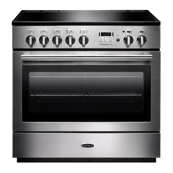
2. Overview DocNo.023-0015 - Overview - 90 induction SC - Prof+ FX Fig. 2.1 Professional + FX ArtNo.273-0003 - 90IN - Prof+ annotated The induction cooker (Fig. 2.1) has the following features: Fig. 2.2 5 induction cooking zones A control panel A multi-function oven A storage drawer The Hob... - Page 8 The very best pans have bases that are very slightly curved up when cold (Fig. 2.3). If you hold a ruler across the bottom Fig. 2.3 you will see a small gap in the middle. When they heat up the metal expands and lies flat on the cooking surface.
- Page 9 may still cause burns. Once the temperature has dropped to Automatic heat-up time at Power level below 60 °C the [H ] will go out. 100% (min:sec) 0:48 Automatic Heat-up, A This function is available on all of the cooking zones. It 2:24 allows rapid heating up of the element to bring the selected 3:50...
-
Page 10: The Multifunction Oven
can immediately restart the Low Temperature function by A & B linked Fig. 2.8 reactivating L1 or L2. Power Boost Setting, P All of the induction cooking zones have Power Boost available, activated by turning the control knob clockwise until [P ] is shown on the hob control display. Power Boost allows additional power to be made available for each of the cooking zones. - Page 11 Use fanned grilling for all your grilling needs and defrost to Fig. 2.10 safely thaw small items of frozen food. Table 2.3 gives a summary of the multi-function modes. ArtNo.270-0025 Proplus MF oven annotated The multi-function oven has many varied uses. We suggest you keep a careful eye on your cooking until you are familiar with each function.
-
Page 12: Energy Saving Panel
cooking large items that need thorough cooking, such as a large meat roast. It is also possible to bake on two shelfs at WARNING! one time, although they will need to be changed over during the cooking time, as the heat at the top of the oven is greater Take great care when removing the divider NOT to than at the base, when using this function. -
Page 13: Operating The Oven
WARNING! Take great care when removing the divider NOT to Fig. 2.14 scratch the inner glass door surface. Scratches in the ArtNo.270-0026 glass can cause stress and may cause the door to fail. Proplus MF oven controls (2) Removing the Divider Make sure the cooker is cool before attempting to remove the divider. -
Page 14: The Clock
The Clock Fig. 2.17 The clock must be set to the time of day before the oven ArtNo.300-0005 2BC minute minder setting will work. 1. Once the cooker is connected and switched on, the display will start to flash. 2. To set the time, turn and hold the Timer (A) knob to the Clock (C) setting and at the same time turn the Adjusting (B) knob either clockwise or counter-clockwise (Fig. - Page 15 To Stop the Multifunction Oven at a Specific ArtNo.301-0008 2BC Fig. 2.22 Stopping the oven 2 Time of Day You have set the required temperature and function mode for the Multifunction Oven and you would like the Multifunction Oven to automatically stop. TOP TIP Make a note of the current time so you do not forget.
- Page 16 To Start and Stop the Multifunction Oven ArtNo.301-0010 2BC Fig. 2.25 Setting the cooking time The Multifunction Oven allows you to automatically start and stop by a combination of the length of the cooking time and the stop time. Giving you the flexibilty to cook casseroles etc while you are out.
-
Page 17: Accessories
Accessories Fig. 2.32 Fig. 2.33 Oven Shelves Each oven is supplied with: ArtNo.326-0014 - Cradle rack (Falcon) ArtNo.326-0013 - Full capacity shelf (Falcon) • Two full capacity shelves (Fig. 2.32) Grill pan tray support (Fig. 2.33) • Two grill pans with trivets (Fig. 2.34) •... -
Page 18: Storage
Storage Fig. 2.41 The bottom drawer is for storing oven trays and other cooking utensils. It can get very warm, so do not store anything in it that may melt or catch fire. Never store flammable materials in the drawer. This includes paper, plastic and cloth items, such as cookbooks, plastic ware and towels, as well as flammable liquids. -
Page 19: Cooking Tips
3. Cooking Tips Cooking with a Multifunction Oven General Oven Tips Remember: not all modes are suitable for all food types. The The wire shelves should always be pushed firmly to the back oven cooking times given are intended for a guide only. of the oven. -
Page 20: Cooking Table
4. Cooking Table DocNo.031-0004 - Cooking table - electric & fan single cavity The oven control settings and cooking times given in the table below are intended to be used Top (T) AS A GUIDE ONLY. Individual tastes may require the temperature to be altered to provide a ArtNo.050-0007 preferred result. -
Page 21: Cleaning Your Cooker
5. Cleaning Your Cooker Isolate the electricity supply before carrying out any major Fig. 5.1 cleaning. Allow the cooker to cool. NEVER use paint solvents, washing soda, caustic cleaners, biological powders, bleach, chlorine based bleach cleaners, coarse abrasives or salt. DO NOT mix different cleaning products –... -
Page 22: Control Panel And Oven Doors
Control Panel and Oven Doors Cleaning Table Cleaners listed (Table 5-1) are available from supermarkets or Avoid using any abrasive cleaners including cream cleaners. For best results use liquid detergents. The control panel electrical retailers as stated. and control knobs should only be cleaned using a soft cloth For enamelled surfaces use a cleaner that is approved for use wrung out in clean hot soapy water –... -
Page 23: Troubleshooting
6. Troubleshooting Interference with and repairs to the hob by My hob is scratched unqualified persons are not allowed. DO NOT try Always use the cleaning methods recommended in this and repair the hob as this may result in injury and guide, and make sure that the pan bottoms are smooth damage the hob. - Page 24 Oven not coming on Fig. 6.1 Is the power on? If not there may be something wrong with the power ArtNo.324-0005 Oven light bulb supply. Is the cooker supply on at the isolator switch? Have you set a cooking function? The timed oven is not coming on when turned on manually Fig.
-
Page 25: Installation
INSTALLATION Check the appliance is electrically safe when you have finished. 7. Installation Dear Installer You will need the following equipment to complete the cooker installation satisfactorily: Before you start your installation, please complete the details • Stability bracket may be installed. below, so that, if your customer has a problem relating to This is not supplied with the cooker but is available at your installation, they will be able to contact you easily. -
Page 26: Positioning The Cooker
INSTALLATION Check the appliance is electrically safe when you have finished. ArtNo.092-0009 - Prof+ 90 FX Clearances #1 Positioning the Cooker Fig. 7.1 The diagrams show the minimum recommended distance 75 mm 75 mm from the cooker to nearby surfaces (Fig. 7.1 and Fig. 7.2). 650 mm The cooker should not be placed on a base. -
Page 27: Levelling
INSTALLATION Check the appliance is electrically safe when you have finished. Removing the Oven Door Fig. 7.3 To remove the oven door, open the door fully. Swivel the locking ‘U’ clips forward to the locking position (Fig. 7.3). Grip the sides of the door, lift upwards and then slide the door forwards (Fig. -
Page 28: Fitting The Stability Bracket Or Chain
INSTALLATION Check the appliance is electrically safe when you have finished. Fitting the Stability Bracket or Chain Fig. 7.7 Unless otherwise stated, a cooker using a flexible gas connector must be secured with a suitable stability device. Stability chain Suitable stability devices are shown in Fig. 7.7, Fig. 7.8 and Fig. -
Page 29: Electrical Connection
INSTALLATION Check the appliance is electrically safe when you have finished. Electrical Connection Current Operated Earth Leakage Breakers The cooker must be installed by a qualified electrician, in The combined use of your cooker and other domestic accordance with all relevant British Standards/Codes of appliances may cause nuisance tripping, so we recommend Practice (in particular BS 7671), or with the relevant national that the cooker is protected on an individual RCD (Residual... -
Page 30: Final Checks
INSTALLATION Check the appliance is electrically safe when you have finished. Final Checks Fig. 7.12 Hob Check Check each cooking zone in turn. Be sure to use pans of the correct size and material. Oven Check Note: Make sure you have set the clock (see ‘Section 2’). ArtNo.281-0026 - Front plinth Turn on the oven. -
Page 31: Circuit Diagram
8. Circuit Diagram Oven Circuit Diagram r (f) Clear boots r (f) Red boots r (f) Red boots Fan output from hob Black boots Terminal 1 on hob Terminal 2 on hob Terminal 4 on hob Terminal 5 on hob Terminal 6 on hob The connections shown in the circuit diagram are for single-phase. -
Page 32: Induction Hob
Induction Hob Circuit Diagram Earth On Terminal Block N(6) On Terminal Block N(4) INDUCTION UNIT DISPLAY w/br L(2) L(3) w/br INTERFACE On Terminal Block BOARD w/br w/br w/br Code Description Code Colour w/br White or brown Left-hand front element Left-hand back element Right-hand back element Right-hand front element Centre element... -
Page 33: Technical Data
DATA BADGE LOCATION: Inside base drawer of cavity. Remove the drawer. COUNTRY OF DESTINATION: GB, IE. Connections Electric 230 / 400 V ~ 50 Hz 3N Dimensions Model Professional+ FX 90 Induction Overall height minimum 905 mm maximum 930 mm Overall width 900 mm Overall depth... -
Page 34: Hotplate Efficiency Data
Hotplate Efficiency Data Brand Rangemaster Model Identification Professional+ FX Size Type Induction Type of Hob Induction Number of electric zones Zone 1 - Ø cm 18.5 Heating Technology Energy Consumption (ECElectric cooking) - Wh/kg Zone 2 - Ø cm 15.5... -
Page 35: Oven Data
Oven Data Brand Rangemaster Model identification Professional+ FX Type of oven Electric Mass Number of cavities Left-hand Efficiency Fuel type Cavity type Power - conventional Power - forced air convection Volume Litres Energy consumption (electricity) - conventional kWh / cycle... - Page 36 Notes...
- Page 39 0800 804 6261 or depending on your mobile network tariff you can For a competitive quote and to arrange for a Rangemaster approved call free on 0370 789 5107. engineer to attend, call Consumer Services on: 0800 804 6261 or...
- Page 40 Registered in England and Wales. Registration No. 354715 Registered Office: Juno Drive, Leamington Spa, Warwickshire, CV31 3RG Rangemaster continuously seeks improvements in specification, design and production of products and thus, alterations take place peri- odically. Whilst every effort is made to produce up-to-date literature, this booklet should not be regarded as an infallible guide to current...
Need help?
Do you have a question about the professional+ fx 90 and is the answer not in the manual?
Questions and answers