Rangemaster Professional+ FX 90 User's Manual & Installation Instructions
Hide thumbs
Also See for Professional+ FX 90:
- User's manual & installation instructions (40 pages) ,
- User's manual & installation instructions (44 pages)

Subscribe to Our Youtube Channel
Related Manuals for Rangemaster Professional+ FX 90


Summary of Contents for Rangemaster Professional+ FX 90
-
Page 1: User Guide
Built from experience USER GUIDE & INSTALLATION INSTRUCTIONS Professional+ FX 90 Dual Fuel... - Page 2 Terms & Conditions 1. This is my Rangemaster is open to residents of UK mainland only, aged 18 years & over. 2. All entries should be submitted to the advertised e-mail address, or Rangemaster UK Facebook, Instagram or Twitter page using the advertised hashtag &...
-
Page 3: Table Of Contents
Contents Before You Start... Cooking Table Personal Safety Cleaning Your Cooker Electrical Connection Safety Daily Care Gas Connection Safety Cleaning for Spills If You Smell Gas Hotplate Burners Peculiar Smells Griddle Ventilation The Wok Cradle Induction and Ceramic Care Oven and Divider Oven Care Control Panel and Oven Doors Hob Care... -
Page 5: Before You Start
1. Before You Start... Personal Safety Your cooker should give you many years of trouble-free cooking if installed and operated correctly. It is important This appliance is for cooking purposes only. It must not be that you read this section before you start. used for other purposes, for example heating a room. -
Page 6: Electrical Connection Safety
Electrical Connection Safety Gas Connection Safety A Gas Safe registered engineer should service the cooker • This cooker is a Class 2 Subclass 1 appliance. and only approved spare parts should be used. • This appliance can be converted for use on another gas. The electrical installation must be installed in accordance •... -
Page 7: Ventilation
Ventilation • DO NOT use water on grease fires and never pick up a flaming pan. Turn the controls off and then smother The use of a cooking appliance results in the production a flaming pan on a surface unit by covering the pan of heat and moisture in the room in which it is installed. -
Page 8: Oven Care
• Take care when placing hot lids onto the hob surface. Fig. 1.1 Lids that have been covering boiling or steaming foods ArtNo.312-0001 Not cooking surface can ‘stick’ to the ceramic glass. Should this occur, DO NOT attempt to lift the lid off the hotplate: this may damage the hob surface. -
Page 9: Hob Care
Cleaning • DO NOT place warm food in the oven to be timed. • DO NOT use a timed oven that is already warm. • Isolate the electricity supply before carrying out any • Use dry oven gloves when applicable – using damp thorough cleaning. -
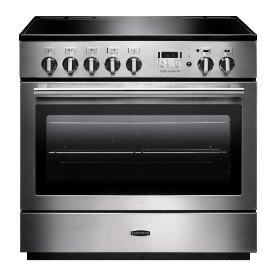
Page 10: Overview
2. Overview DocNo.025-0101 - Overview - 90 DF SC - Prof+ FX Fig. 2.1 Professional + FX ArtNo.270-0029 - Prof+ 90SC annotated The dual fuel single cavity cooker (Fig. 2.1) has the following Fig. 2.2 ArtNo.270-0001 features: Proplus control to high 5 hotplate burners including a wok burner Control panel incorporating a timer Multifunction oven... -
Page 11: Wok Burner
If, when you let go of the control knob, the burner goes out, Fig. 2.3 then the FSD has not been bypassed. Turn the control knob ArtNo.270-0003 Proplus control to low to the OFF position and wait for one minute before you try again, this time making sure to hold in the control knob for slightly longer. -
Page 12: The Griddle
The Griddle Fig. 2.10 The griddle fits the left-hand well, front to back (Fig. 2.11). It is designed for cooking food on directly. DO NOT use pans of any kind on it. The griddle surface is non-stick and metal cooking utensils (e.g. spatulas) will damage the surface. Use heat resistant plastic or wooden utensils. - Page 13 Multifunction Oven Modes Conventional Oven (Top and Base Heat) (Fig. 2.13) Defrost This function combines the heat from the top and base elements. It is particularly suitable for roasting This function operates the fan(s) to circulate cold air and baking pastry, cakes and biscuits. only.
-
Page 14: Energy Saving Panel
Energy Saving Panel Fig. 2.13 ArtNo.270-0025 The oven has a divider feature (Fig. 2.14). With this in place Proplus MF oven annotated only one half of the oven is heated and only the right-hand side elements are used. This saves energy and is ideal for cooking most foods. -
Page 15: Operating The Oven
Operating the Oven Fig. 2.17 The multifunction oven has two controls: a function selector and a temperature setting knob (Fig. 2.17). ArtNo.270-0026 Turn the function selector control to a cooking function. Fig. Proplus MF oven controls (2) 2.18 shows the control set for convectional oven cooking. Turn the oven temperature knob to the temperature you need. -
Page 16: Accessories
Accessories Fig. 2.20 Fig. 2.21 Each oven is supplied with: • Two full capacity shelves (Fig. 2.20) Grill pan tray support (Fig. 2.21) ArtNo.326-0013 - Full capacity shelf • ArtNo.326-0004 - Cradle shelf (Falcon) Two grill pans with trivets (Fig. 2.22) •... -
Page 17: The Clock
3. The Clock The clock must be set to the time of day before the oven Fig. 3.1 ArtNo.300-0005 2BC will work. minute minder setting Setting the Clock 1. Once the cooker is connected and switched on, the display will start to flash. 2. - Page 18 To Stop the Oven at a Specific Time of Day Fig. 3.5 You have set the required temperature and function mode and you would like the oven to automatically stop. TOP TIP Make a note of the current time so you do not forget. 1.
- Page 19 To Start and Stop the Oven Automatically Fig. 3.9 The timer allows you to automatically start and stop by a combination of the length of the cooking time and the stop time. Giving you the flexibility to cook casseroles etc while you are out.
-
Page 20: Cooking Tips
4. Cooking Tips Cooking with a Multifunction Oven General Oven Tips Remember: not all modes are suitable for all food types. The The wire shelves should always be pushed firmly to the back oven cooking times given are intended for a guide only. of the oven. -
Page 21: Cooking Table
5. Cooking Table DocNo.031-0004 - Cooking table - electric & fan single cavity The oven control settings and cooking times given in the table below are intended to be used Top (T) AS A GUIDE ONLY. Individual tastes may require the temperature to be altered to provide a ArtNo.050-0007 preferred result. -
Page 22: Cleaning Your Cooker
6. Cleaning Your Cooker Isolate the electricity supply before carrying out any major Fig. 6.1 cleaning. Allow the cooker to cool. NEVER use paint solvents, washing soda, caustic cleaners, biological powders, bleach, chlorine based bleach cleaners, coarse abrasives or salt. DO NOT mix different cleaning products –... -
Page 23: Griddle
The Wok Burner Fig. 6.2 When reassembling the wok burner (Fig. 6.2) turn over the large base ring and find the ‘D’ shaped area (Fig. 6.3). Turn the head until the ‘D’ matches the one on the burner base. Flip the burner over once again and place it on the burner base. -
Page 24: Cleaning Table
Cleaning Table Cleaners listed (Table 6.1) are available from supermarkets or electrical retailers as stated. For enamelled surfaces use a cleaner that is approved for use on vitreous enamel. Regular cleaning is recommended. For easier cleaning, wipe up any spillages immediately. Hotplate Part Finish... -
Page 25: Troubleshooting
7. Troubleshooting Hotplate/Cooktop ignition or hotplate burners faulty Food is cooking too slowly, too quickly, or burning Is the power on? Is the clock illuminated? Cooking times may differ from your previous oven. If not, there maybe something wrong with the power Check that you are using the recommended supply. - Page 26 Oven light is not working Fig. 7.1 The bulb has probably burnt out. You can buy a replacement bulb (which is not covered under the warranty) from a good electrical shop. Ask for a 15 W – 230 V lamp, FOR OVENS. It must be a special bulb, heat ArtNo.324-0005 Oven light bulb resistant to 300 °C (Fig.
-
Page 27: Installation
INSTALLATION Check the appliance is electrically safe and gas sound when you have finished. 8. Installation Dear Installer In the UK the cooker must be installed in accordance with: Before you start your installation, please complete the details below, so that, if your customer has a problem relating to •... -
Page 28: Location Of Cooker
INSTALLATION Check the appliance is electrically safe and gas sound when you have finished. Location of Cooker The cooker may be installed in a kitchen/kitchen diner but NOT in a room containing a bath or shower. This appliance is designed for domestic cooking only. Use for any other purpose could invalidate any warranty or liability claim. - Page 29 INSTALLATION Check the appliance is electrically safe and gas sound when you have finished. Checking the Parts: You will need the following equipment to complete the cooker installation satisfactorily: Pan supports Griddle • Stability bracket: If the cooker is to be supplied with gas through a flexible hose, a stability bracket or chain MUST be fitted.
-
Page 30: Positioning The Cooker
INSTALLATION Check the appliance is electrically safe when you have finished. Positioning the Cooker Fig. 8-1 ArtNo.092-0003 - 90SC cooker min spacings Fig. 8-1 and Fig. 8-2 show the minimum recommended distance from the cooker to nearby surfaces. 75 mm 75 mm The cooker should not be placed on a base. -
Page 31: Moving The Cooker
INSTALLATION Check the appliance is electrically safe and gas sound when you have finished. Moving the Cooker Fig. 8.1 On no account try and move the cooker while it is plugged into the electricity supply. The cooker is very heavy, so take extra care. We recommend that two people manoeuvre the cooker. -
Page 32: Repositioning The Cooker Following
INSTALLATION Check the appliance is electrically safe and gas sound when you have finished. Fitting the Stability Bracket or Chain Stability bracket Fig. 8.5 Unless otherwise stated, a cooker using a flexible gas connector must be secured with a suitable stability device. Suitable stability devices are shown in Fig. -
Page 33: Gas Connection
INSTALLATION Check the appliance is electrically safe and gas sound when you have finished. Gas Connection Fig. 8.1 Conversion to Another Gas If the appliance is to be converted to another gas do the conversion at this point. See ‘Conversion to LP Gas’ . Gas Connection ‘A’... -
Page 34: Electrical Connection
INSTALLATION Check the appliance is electrically safe when you have finished. Electrical Connection Current Operated Earth Leakage Breakers The cooker must be installed by a qualified electrician, in The combined use of your cooker and other domestic accordance with all relevant British Standards/Codes of appliances may cause nuisance tripping, so we recommend Practice (in particular BS 7671), or with the relevant national that the cooker is protected on an individual RCD (Residual... -
Page 35: Final Checks And Fittings
INSTALLATION Check the appliance is electrically safe and gas sound when you have finished. Final Checks and Fittings Fig. 8.1 Hotplate Check Check each burner in turn. There is a flame supervision device (FSD) that stops the flow of gas to the burner if the flame ArtNo.062-0001 - 90 Prof+ FX - Removing the door goes out. -
Page 36: To Fit The Drawer
INSTALLATION Check the appliance is electrically safe and gas sound when you have finished. To fit the drawer To remove the drawer DO NOT use the levers to remove the drawer... -
Page 37: Conversion To Lp Gas
WARNING – SERVICING TO BE CARRIED OUT ONLY BY AN AUTHORISED PERSON Disconnect from electricity and gas before servicing. Check appliance is safe when you have finished. 9. Conversion to LP Gas Check in the ‘Technical Data’ section at the back of these Fig. -
Page 38: Stick On Label
WARNING – SERVICING TO BE CARRIED OUT ONLY BY AN AUTHORISED PERSON Disconnect from electricity and gas before servicing. Check appliance is safe when you have finished. Stick on Label Stick the LP gas label over the natural gas part of the appliance data label. -
Page 39: Circuit Diagram
10. Circuit Diagram Clear boots r (f) r (f) r (f) r (f) Black boots The connections shown in the circuit diagram are for single-phase. The ratings are for 230 V 50 Hz. Code Description Code Description Code Colour Master function controller Cooling fan Blue Drone function controller... -
Page 40: Technical Data
29 mbar 230/400 V 50 Hz Propane 37 mbar See the appliance badge for test pressures. Dimensions Model Professional+ FX 90 Dual Fuel Overall height minimum 905 mm maximum 930 mm Overall width 900 mm Overall depth 608 mm excluding handles, 645 mm including handles... - Page 41 Hotplate Efficiency Brand Rangemaster Model Identification Professional+ FX Size 90 Single Cavity Type Dual Fuel Type of Hob Number of gas burners Auxiliary / Small Burner (EE gas burner) Semi Rapide / Medium Burner (EE gas burner) Semi Rapide / Medium Burner (EE gas burner)
- Page 42 Oven Data Brand Rangemaster Model identification Professional+ FX Type of oven Electric Mass Number of cavities Single Cavity Efficiency Fuel type Electric Cavity type Multifunction* = Drop Down Door Power - conventional 2.75 Power - forced air convection Volume Litres...
- Page 43 Gas Safe registered engineer for gas appliances or an approved electrician for electrical models. CONSUMER SERVICE For a competetive quote and to arrange for a Rangemaster approved engineer to attend, call Consumer Services on: If you have any product enquiries, or in the event of a problem 0800 804 6261 or 0370 789 5107 from a mobile.
- Page 44 Registered Office: Juno Drive, Leamington Spa, Warwickshire, CV31 3RG Rangemaster continuously seeks improvements in specification, design and production of products and thus, alterations take place periodically. Whilst every effort is made to produce up-to-date literature, this brochure should not be regarded as...
Need help?
Do you have a question about the Professional+ FX 90 and is the answer not in the manual?
Questions and answers