Rangemaster Professional+ User Manual
90 dual fuel fsd
Hide thumbs
Also See for Professional+:
- User's manual & installation instructions (48 pages) ,
- User's manual & installation instructions (32 pages) ,
- User's manual & installation instructions (44 pages)

Related Manuals for Rangemaster Professional+


Summary of Contents for Rangemaster Professional+
-
Page 1: User Guide
� ������������ ArtNo.000-0012 Professional + logo 90 Dual Fuel FSD User Guide & Installation & Service Instructions U109781 - 07... -
Page 2: Table Of Contents
Contents Before You Start... Troubleshooting Important! Installation Installation and Maintenance Dear Installer Peculiar smells Safety Requirements and Regulations If you smell gas Provision of Ventilation Ventilation Location of Cooker Personal Safety Conversion Cooker Care Positioning the Cooker Cleaning Moving the Cooker Cooker Overview Completing the Move Hotplate Burners... -
Page 3: Before You Start
1. Before You Start... If you smell gas Your cooker should give you many years of trouble-free cooking if installed and operated correctly. It is important • DO NOT turn electric switches on or off. that you read this section before you start, particularly if you •... -
Page 4: Cooker Care
DO NOT use harsh abrasive cleaners or sharp metal DO NOT use water on grease fires and never pick scrapers to clean the oven door glass since they can up a flaming pan. Turn the controls off and then scratch the surface, which may result in shattering of smother a flaming pan on a surface unit by covering the glass. -
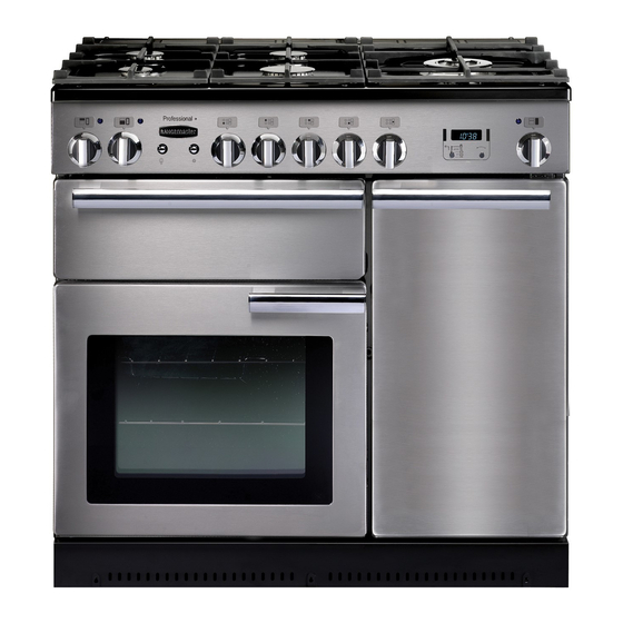
Page 5: Cooker Overview
2. Cooker Overview DocNo.020-0006 - Overview - 90DF - Prof+ Fig.2-1 � � � � � The 90 dual fuel cooker (Fig.2-1) has the following features: Fig.2-2 ArtNo.270-0001 5 hotplate burners including a wok burner Proplus control to high A control panel A glide-out grill Main fan oven Tall fan oven... -
Page 6: Wok Burner
If, when you let go of the control knob, the burner goes out, Fig.2-3 then the FSD has not been bypassed. Turn the control knob ArtNo.270-0003 Proplus control to low to the OFF position and wait for one minute before you try again, this time making sure to hold in the control knob for slightly longer. -
Page 7: The Wok Cradle
The Wok Cradle ArtNo.311-0006 Correct wok sizes Fig.2-9 The wok cradle is designed to fit a Professional 35cm Wok (available from our cookware collection – Part Code RM095). If you use a different Wok, make sure that it fits the cradle. Woks vary very widely in size and shape. -
Page 8: The Glide-Out Grill
The Glide-out Grill Fig.2-15 Open the door and pull the grill pan carriage forward using the handle (Fig.2-15). The grill has two elements that allow either the whole area of the pan to be heated or just the right-hand half. Adjust the heat to suit by turning the knob. -
Page 9: The Clock
The Clock Fig.2-20 ArtNo.300-0004 2-button clock annotated You can use the timer (Fig.2-20) to turn the left-hand oven on and off. The clock must be set to the time of day before the ovens will work. Note: When using the timer functions, first set the clock as required before setting the oven temperature and selecting the oven function (multi-function ovens only). -
Page 10: Manual Cooking
You cannot set a start time directly – this is set Fig.2-25 Fig.2-26 automatically by a combination of the ‘cook time’ and ‘stop time’. ArtNo.301-0009 2BC ArtNo.301-0010 2BC Setting the cooking timer Setting the cooking time Turn the Timer knob to the () position (Fig.2-25). Use the Adjusting knob to set the ‘cook time’... -
Page 11: Accessories
Accessories Fig.2-35 Fig.2-36 Oven Shelves – Left-hand (Main) Oven In addition to the flat shelves (Fig.2-33), some models are supplied with a drop shelf (Fig.2-34). The drop shelf increases the possibilities for oven shelf spacing. The oven shelves can be easily removed and refitted. ArtNo.320-0011 Removing the shelf 1 ArtNo.320-0012 Removing the shelf 2 Pull the shelf forward until the back of the shelf is stopped by... -
Page 12: Cooking Tips
DocNo.030-0006 - Cooking tips - 90 electric 3. Cooking Tips Tips on Cooking with the Timer General Oven Tips If you want to cook more than one dish, choose dishes that The wire shelves should always be pushed firmly to the back require approximately the same cooking time. -
Page 13: Cooking Table
4. Cooking Table DocNo.031-0004 - Cooking table - electric & fan single cavity The oven control settings and cooking times given in the table below are intended to be used AS A GUIDE ONLY. Individual tastes may require the temperature to be altered to provide a preferred result. -
Page 14: Cleaning Your Cooker
More information is available through either the Cookware Collection brochure supplied with your cooker � or our website www.rangemaster.co.uk. Hotplate Burners � Some models have a separate trim ring, which fits on the burner head. -
Page 15: The Griddle
The grill pan and grid should be washed in hot soapy water, or using our recommended Rangemaster cleaning solution. After grilling meats or any foods that soil, leave to soak for a few minutes in the sink immediately after use.Stubborn particles may be removed from the grid by using a nylon brush. -
Page 16: Ovens
Glass Fronted Door Panels Fig.5-10 The oven door front panels can be taken off so that the glass panels can be cleaned. Move the cooker forward to gain access to the sides (see the ‘Moving the Cooker’ section under ‘Installation’). Open the oven door slightly and remove the front panel fixing screws from the door sides, two each side (Fig.5-10). -
Page 17: Cleaning Table
Cleaning Table Cleaners listed are available from supermarkets or electrical retailers as stated. For enamelled surfaces use a cleaner that is approved for use on vitreous enamel. Regular cleaning is recommended. For easier cleaning, wipe up any spillages immediately. To help keep your oven clean, cover meat when roasting, with foil or use a roasting bag. -
Page 18: Troubleshooting
6. Troubleshooting Hotplate ignition or hotplate burners faulty Power failure Is the power on? Is the clock illuminated? In the event of a failure in the electrical supply, remember to reset the clock to ensure that the timed If not, there maybe something wrong with the power oven continues to operate. - Page 19 An oven light is not working Fig.6-1 The bulb has probably burnt out. You can buy a replacement bulb (which is not covered under the warranty) from a good electrical shop. Ask for a 15W ArtNo.324-0005 Oven light bulb – 230V lamp, FOR OVENS. It must be a special bulb, heat resistant to 300°C (Fig.6-1).
-
Page 20: Installation
7. Installation Dear Installer In the UK the cooker must be installed in accordance with: Before you start your installation, please complete the details below, so that, if your customer has a problem relating to All relevant British Standards / Codes of Practice, in your installation, they will be able to contact you easily. -
Page 21: Location Of Cooker
Location of Cooker Checking the Parts: The cooker may be installed in a kitchen/kitchen diner but Levelling tool and Allen keys 3 pan supports NOT in a room containing a bath or shower. This appliance is designed for domestic cooking only. Use for any other purpose could invalidate any warranty or ArtNo.000-0002 Classic tools liability claim. -
Page 22: Positioning The Cooker
Positioning the Cooker Fig.7-1 ArtNo.090-0009 - 90 2BC cooker min spacings Fig.7-1 shows the minimum recommended distance from the cooker to nearby surfaces. ���� ���� ��� ��� ����� The cooker should not be placed on a base. ��� Above hotplate surround should be level with, or above, any adjacent work surface. -
Page 23: Completing The Move
Lowering the Two Rear Rollers Fig.7-5 First fit the levelling tool on the hexagonal adjusting nut ArtNo.010-0002 Rear roller nut (Fig.7-5). Make 10 complete (360º) turns clockwise (Fig.7-6). (This means turning and removing the levelling tool 20 times). Make sure you lower BOTH REAR ROLLERS. There are two adjusting nuts, one for each roller, at both the front bottom corners of the cooker. -
Page 24: Conversion To Another Gas
As you progress, make sure that both the electricity cable and Fig.7-10 gas hose always have sufficient slack to allow the cooker to move. ��� � ��� With a stability chain fitted, release it as you ease the cooker out. Do not forget to refit it when you replace the cooker. -
Page 25: Electrical Connection
Screw connect the threaded end of the hose into the gas Fig.7-11 inlet. After completing the gas connection, ensure that the cooker is gas sound with a pressure test. Pressure Testing The gas pressure can be measured at one of the centre hotplate burner injectors (not the Wok burner). -
Page 26: Fitting The Plinth
Oven Check Fig.7-13 Set the clock as described earlier in the instructions, and then turn on the ovens. Check that the oven fans start to turn and that the ovens start to heat up. Note: The oven light bulb is not included in the guarantee. Turn off... -
Page 27: Conversion To Lp Gas
WARNING – SERVICING TO BE CARRIED OUT ONLY BY AN AUTHORISED PERSON Disconnect from electricity and gas before servicing. Check appliance is safe when you have finished. 8. Conversion to LP gas Check the technical data section at the back of the book Fig.8-1 that the hob is convertible to the gas you want to use. -
Page 28: Circuit Diagram
9. Circuit Diagram � � � � � � � � � � � � � � � �� � � � � � � �� �� � �� �� � � �� �� �� � �� �� �� � �... -
Page 29: Technical Data
10. Technical Data ArtNo.105-0008 - Technical data - 90 induction - Elan The cooker is category II2H3+ It is supplied set for group H natural gas. A conversion kit from NG to LP is packed with the cooker. INSTALLER: Please leave these instructions with the User. DATA BADGE LOCATION: Cooker back, serial number repeater badge below oven door opening. - Page 32 DocNo.000-0001 - Back cover Rangemaster �������������� ����������� ������� ����� w w w.ra n g e m a s t e r.c o .u k ArtNo.000-0003 CE logo...
Need help?
Do you have a question about the Professional+ and is the answer not in the manual?
Questions and answers