Sign In
Upload
Manuals
Brands
Advantech Manuals
Motherboard
PCM-5825
Advantech PCM-5825 Manuals
Manuals and User Guides for Advantech PCM-5825. We have
1
Advantech PCM-5825 manual available for free PDF download: User Manual
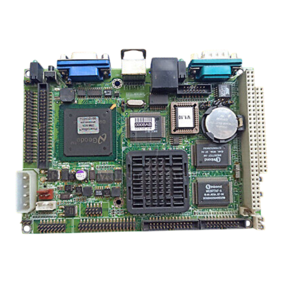
Advantech PCM-5825 User Manual (122 pages)
NS Geode Single Board Computer with CPU, 4 COMs, VGA/LCD, Ethernet, and Audio Interface
Brand:
Advantech
| Category:
Motherboard
| Size: 2 MB
Table of Contents
Copyright Notice
2
Table of Contents
4
Chapter 1 General Information
11
Introduction
12
Features
13
Specifications
14
Standard SBC Functions
14
Local-Bus Flat Panel/Vga Interface
15
Audio Function
15
Ethernet Interface
15
Solid State Disk
16
Mechanical and Environmental
16
Board Layout and Dimensions
17
Chapter 2 Installation
19
Jumpers and Connectors
20
Table 2-2: Connectors
21
Locating Jumpers
22
Locating Connectors
23
Component Side
23
Setting Jumpers
24
Introduction
24
Settings Details
25
Safety Precautions
25
J1: Audio Power Source
25
J2: Clear CMOS
25
J3: COM2 Selector
25
J4: Watchdog Timer
25
J5: Buzzer
25
J6: LCD Power
25
Installing DRAM (Sodimms)
26
Introduction
26
Installing Sodimms
26
IDE Hard Drive Connector (CN15)
27
Connecting the Hard Drive
27
Compactflash™ Disk (CN24)
28
Floppy Drive Connector (CN4)
28
Connecting the Floppy Drive
28
Parallel Port Connector (CN3)
29
Keyboard and PS/2 Mouse Connector (CN21)
29
Power Connectors
30
Main Power Connector +5 V, +12 V (CN13)
30
Auxilary Power Connector (CN1)
30
CPU Fan Power Connector (CN6)
30
IR Connector (CN12)
30
Audio Interfaces (CN5, CN9, J1)
30
Audio Connector (CN5)
30
CD Audio Input Connector (CN9)
31
Audio Power Source Setting (J1)
31
Serial Ports (CN19, CN18, CN2)
31
COM1 RS-232 Port (CN19)
31
COM2 RS-232/422/485 Selection (CN18)
32
COM3/COM4 RS-232 Port (CN2)
32
Share IRQ
32
VGA Interface Connections
33
CRT Display Connector (CN22)
33
Flat Panel Display Connector (CN16)
33
LCD Power Setting (J6)
33
Ethernet Interface Connections
34
100Base-T RJ-45 Connector (CN20)
34
Ethernet LED and Hdd/Power Leds
34
LED1 (Ethernet LED)
34
LED2 (Power and HDD LED)
34
Watchdog Timer Configuration
35
Watchdog Timer Action (J4)
35
USB Connectors (CN7)
35
Chapter 3 Software Configuration
37
Introduction
38
Utility CD Disk
38
VGA Display Software Configuration
39
Connections for Two Standard Lcds
41
Connections for 640 X 480 TFT Color LCD
41
Connections for 800 X 600 TFT Color LCD
42
Ethernet Interface Configuration
43
Chapter 4 Award BIOS Setup
45
System Test and Initialization
46
System Configuration Verification
46
Award BIOS Setup
47
Entering Setup
47
Standard CMOS Setup
48
BIOS Features Setup
49
Chipset Features Setup
50
Power Management Setup
51
Pnp/Pci Configuration
52
Integrated Peripherals
53
Load BIOS Defaults
54
Change Password
55
Auto Detect Hard Disk
56
Save & Exit Setup
56
Exit Without Saving
56
Chapter 5 SVGA Setup
57
Introduction
58
Chipset
58
Display Memory
58
Installation of SVGA Driver
59
Installation for Windows 3.1
60
Installation for Cyrix Mediagx
63
Installation for Windows NT
67
Further Information
72
Chapter 6 Audio
73
Introduction
74
Installation of Audio Driver
74
Installation for Windows 95/98
75
Installation for Windows NT
79
Chapter 7 PCI Bus Ethernet Interface
83
Introduction
84
Installation of Ethernet Driver
84
Installation for MS-DOS and Windows 3.1
84
Installation for Windows 95/98
85
Installation for Windows NT
88
Further Information
91
Appendix A Pin Assignments
93
CRT Display Connector (CN22)
94
COM2 RS-232/422/485 Serial Port (CN18)
94
Keyboard and Mouse Connnector (CN21)
95
Main Power Connector (CN3)
95
IDE Hard Drive Connector (CN15)
96
COM1 RS-232 Serial Port (CN19)
96
COM3/COM4 Connector (CN2)
97
Ethernet 100Base-T Connector (CN20)
97
Auxilary Peripheral Power Connector (CN1)
98
Floppy Drive Connector (CN4)
98
Parallel Port Connector (CN3)
99
IR Connector (CN12)
100
USB Connector (CN7)
100
Audio Connector (CN5)
100
CD Audio Connector (CN9)
101
CPU Fan Power Connector (CN6)
101
18-Bit LCD Display Connector (CN16)
102
Compactflash™ Connector (CN24)
103
Appendix B System Assignments
105
System I/O Ports
106
DMA Channel Assignments
107
Interrupt Assignments
108
1St MB Memory Map
109
Appendix C Installing PC/104 Modules
111
Installing PC/104 Modules
112
Table C-1: PC/104 Connectors (CN14)
114
Appendix D Programming the Watchdog Timer
115
Programming the Watchdog Timer
116
Appendix E Mechanical Drawings
119
Component Side
120
Solder Side
121
Advertisement
Advertisement
Related Products
Advantech PCM-5864E
Advantech PCM-5864L
Advantech PCM-5864
Advantech PCM-5820L
Advantech PCM-5820 Series
Advantech PCM-5820EL
Advantech PCM-5820E
Advantech PCM-5823 Series
Advantech PCM-5823-D0A1
Advantech PCM-5823-G0A1
Advantech Categories
Motherboard
Computer Hardware
Desktop
Touch Panel
Network Router
More Advantech Manuals
Login
Sign In
OR
Sign in with Facebook
Sign in with Google
Upload manual
Upload from disk
Upload from URL